
Datasheet


13
L
21
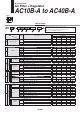
Symbol
Description
q
Body size
10 20 30 40
w
Pipe thread type
—
Metric thread (M5)
———
Rc
—
N
Note 1)
NPT
—
F
Note 2)
G
—
+
e
Port size
M5
M5
———
01
1/8
—
——
02
1/4
—
03
3/8
——
04
1/2
———
06
3/4
———
+
r
Option
Note 3)
a
Float type
auto drain
—
Without auto drain
C
Note 4)
N.C. (Normally closed) Drain port is closed when pressure is not applied.
D
Note 5)
N.O. (Normally open) Drain port is open when pressure is not applied.
——
+
b
Pressure
gauge
Note 6)
—
Without pressure gauge
G
Round type pressure gauge (without limit indicator)
———
Round type pressure gauge (with limit indicator)
—
M
Round type pressure gauge (with colour zone)
—
+
t
Attachment
c Check valve
—
Without attachment
K
Mounting position: AW+K+AL
—
Note 7)
+
d
Pressure
switch
—
Without attachment
S
Note 8)
Mounting position: AW+S+AL
—
+
e
Pressure relief
3 port valve
—
Without attachment
V
Mounting position: AW+AL+V
—
+
y
Semi-standard
f
Set
pressure
Note 9)
—
0.05 to 0.7 MPa setting
1
0.02 to 0.2 MPa setting
+
g Bowl
Note 10)
—
Polycarbonate bowl
2
Metal bowl
6
Nylon bowl
8
Metal bowl with level gauge
——
C
With bowl guard
—
—
Note 11)
—
Note 11)
6C
With bowl guard (Nylon bowl)
—
—
Note 12)
—
Note 12)
+
h
Filter
Note 13)
regulator
drain port
—
With drain cock
J
Note 14)
Drain guide 1/8
—
——
Drain guide 1/4
——
W
Note 15)
Drain cock with barb fi tting (for ø6 x ø4 nylon tube)
——
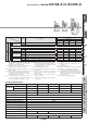
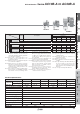
Symbol
Air Combination
Filter Regulator + Lubricator
AC10A-A to AC40A-A
AC
• Option/Semi-standard: Select one each for a to l.
• Option/Attachment/Semi-standard symbol: When more than one
specifi cation is required, indicate in alphanumeric order.
Example) AC30A-F03DM-KSV-13NR-A
AA
30
q
03
e
DG
rtyw
How to Order