
User Manual
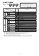

20 30 40
Nil
● ● ●
N
● ● ●
F
● ● ●
+
01
● - -
02
● ● ●
03
- ● ●
04
- - ●
06
- - ●
+
Nil
Without auto drain
● ● ●
C
N.C. (Normally closed) Drain port is closed when pressure is not applied.
● ● ●
D
N.O. (Normally open) Drain port is open when pressure is not applied.
- ● ●
+
Nil
Without pressure gauge
● ● ●
E
● ● ●
G
Round type pressure gauge (with limit indicator)
● ● ●
M
Round type pressure gauge (with color zone)
● ● ●
E1
Output:NPN output / Electrical entry:Wiring bottom entry
● ● ●
E2
Output:NPN output / Electrical entry:Wiring top entry
● ● ●
E3
Output:PNP output / Electrical entry:Wiring bottom entry
● ● ●
E4
Output:PNP output / Electrical entry:Wiring top entry
● ● ●
+
Nil Without attachment
● ● ●
S Mounting position:AW+S+AFM
● ● ●
+
Nil Without attachment
● ● ●
V
Mounting position:AW+AFM+V
● ● ●
V1
Mounting position:V+AW□K+AFM
● ● ●
+
Nil 0.05 to 0.85 MPa setting
● ● ●
1
0.02 to 0.2 MPa setting
● ● ●
+
Nil Polycarbonate bowl
● ● ●
2
Metal bowl
● ● ●
6
Nylon bowl
● ● ●
8
Metal bowl with level gauge
- ● ●
C
With bowl guard
● - -
6C
With bowl guard (Nylon bowl)
● - -
+
Nil With drain cock
● ● ●
Drain guide 1/8
● - -
Drain guide 1/4
- ● ●
W Drain cock with barb fitting (for φ 6 x φ 4 nylon tube)
- ● ●
+
Nil Relieving type
● ● ●
N
Non-relieving type
● ● ●
+
Nil
Flow direction:Left to right
● ● ●
R
Flow direction:Right to left
● ● ●
+
Nil
● ● ●
Z
○ ○ ○
ZA Digital pressure switch:With unit conversion function
△ △ △
Name plate, caution plate for bowl, and pressure gauge in imperial units:MPa
Name plate, caution plate for bowl, and pressure gauge in imperial units:psi, °F
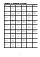
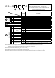
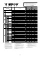
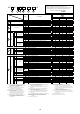
Symbol
Description
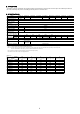
Port size
1/8
1/4
3/8
Body size
Pipe thread type
Rc
NPT
G
1/2
3/4
Option
a
Float type
auto drain
b
Pressure gauge
Digital
pressure
switch
Square embedded type pressure gauge (with limit indicator)
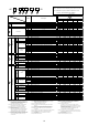
Attachment
c
Pressure switch
d
Pressure relief
3 port valve
e
Set pressure
f
Bowl
g
Filter regulator
Mist separator
drain port
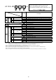
18
J
h
Exhaust
mechanism
i
Flow direction
j
Pressure unit
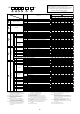
Semi-standard
1
2
3
4
6
5
Note13)
Note18)
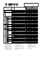
AC
30
-
03
DE
1N
-
B
-
1
3
4
5
2
1N
6
-
D
Note19)
Note 1)
Note 2)
・Option / Semi-standard : Select one each for a to j.
・Option / Attachment / Semi-standard symbol : When more than
one specification is required, indicate in alphanumeric order.
Example) AC30D-F03DE1-SV-16NR-B
Note 3)
Note 6)
Note 4)
Note 5)
Note 8)
Note 7)
Note 9)
Note 10)
Note 14)
Note 15)
Note 16)
Note 17)
Note11)
Note12)
Note11)
Note12)
Note18)
Note19)
Note18)
Note19)
Note 1) Drain guide is NPT1/8 (applicable to the AC20D-B) and
NPT1/4 (applicable to the AC30D-B/AC40D-B)
The auto drain port comes with φ3/8" One-touch fitting
(applicable to the AC30D-B/AC40D-B).
Note 2) Drain guide is G1/8 (applicable to the AC20D-B) and
G1/4 (applicable to the AC30D-B/AC40D-B).
Note 3) Option G, M are not assembled and supplied loose
at the time of shipment.
Note 4) When pressure is not applied, condensate which
does not start the auto drain mechanism will be left in
the bowl. Releasing the residual condensate before
ending operations for the day is recommended.
Note 5) If the compressor is small (0.75 kW, discharge flow is less
than 100 L/min[ANR]), air leakage from the drain cock
may occur during start of operations. N.C. type is
recommended.
Note 6) When the pressure gauge is attached, a 1.0 MPa pressure gauge
will be fitted for standard (0.85 MPa) type.
0.4 MPa pressure gauge for 0.2 MPa type.
Note 7) The bracket position varies depending on the pressure switch
mounting.
Note 8) Make sure that the outlet pressure is released to atmospheric
pressure using a pressure gauge.
Note 9) Pressure can be set higher than the specification pressure
in some cases, but use pressure within the specification range.
Note 10) Refer to Chemical data on page 3 for chemical resistance
of the bowl.
Note 11) A bowl guard is provided as standard equipment (polycarbonate).
Note 12) A bowl guard is provided as standard equipment (nylon).
Note 13) Float type auto drain: The combination of C and D is
not possible.
Note 14) Without a valve function.
Note 15) The combination of metal bowl: 2 and 8 is not available.
Note 16) For pipe thread type: NPT.
This product is for overseas use only according to the new
Measurement Law. (The SI unit typeis provided for use in Japan.)
Cannot be used with M: Round pressure gauge (with color zone).
Available by request for special.
The digital pressure switch will be equipped with the unit
conversion function, setting to psi initially.
Note 17) For options: E1, E2, E3, E4. This product is for overseas use only
according to the new Measurement Law. (The SI unit is provided
for use in Japan.)
Note 18) ○: For pipe thread type: NPT only
Note 19) △: Select with options: E1, E2, E3, E4.