Wireless Broadband Router User Guide The information furnished by SMC Networks, Inc. (SMC) is believed to be accurate and reliable. However, no responsibility is assumed by SMC for its use, nor for any infringements of patents or other rights of third parties which may result from its use. No license is granted by implication or otherwise under any patent or patent rights of SMC. SMC reserves the right to change specifications at any time without notice. Copyright © 2001 by SMC Networks, Inc.
Trademarks: SMC is a registered trademark and Barricade is a registered trademark of SMC Networks, Inc. Other products and company names are trademarks or registered trademarks of their respective holders. FCC Interference Statement: This equipment has been tested and found to comply with the limits for a Class B digital device pursuant to Part 15 of the FCC rules. These limits are designed to provide reasonable protection against radio interference in a commercial environment.
Table of Contents Chapter 1 Introduction...............................................................................4 1.1 Functions and Features...................................................................4 1.2 Packing List ....................................................................................5 Chapter 2 Hardware Installation................................................................6 2.1 Panel Layout ...............................................................................
5.4 Configuring on Unix-based Platforms ..........................................40 Appendix A: TCP/IP Configuration for Windows 95/98 ...........................41 A.1 Install TCP/IP Protocol Into Your PC ..........................................41 A.2 Set TCP/IP Protocol for Working With IP Sharer........................
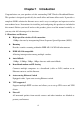
Chapter 1 Introduction Congratulations on your purchase of this outstanding SMC Wireless Broadband Router. This product is designed specifically for small office and home office needs. It provides a complete SOHO solution for Internet access and is easy to configure and operate even for non-technical users. Instructions for installing and configuring this product are included in this manual.
l DHCP server supported All of the networked computers can retrieve TCP/IP settings automatically from this product. l Web-based configuring Configurable through any networked computer’s web browser using Netscape or Internet Explorer. l MAC Address Access Control supported Allows you to assign different access rights for different users. l Virtual Server supported Enables you to expose WWW, FTP and other services on your LAN for access by Internet users.
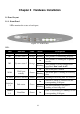
Chapter 2 Hardware Installation 2.1 Panel Layout 2.1.1. Front Panel LEDs monitor the status of each port. Figure 2-1 Front Panel LED: LED Function POWER Power indication M1 M2 System status 1 System status 2 Color Status Description Green On Power is being applied to this product. Orange Blinking This product is functioning properly. On This product is working for a specific service. Orange Blinking On WAN WAN port activity Green W.
2.1.2. Rear Panel The rear panel features three 10/100 Mbps Ethernet ports and one Wide Area network (WAN) port. The WAN port connects your DSL or cable modem to the router. The LAN ports are used to connect to your computers or other network devices. Figure 2-2 Rear Panel Ports: Port RESET Description To reset system settings to factory defaults, please follow the steps: 1. Power off the device, 2. Press the reset button and hold, 3. Power on the device, 4. Keep the button pressed about 5 seconds, 5.
2.2 Procedure for Hardware Installation 1. Decide Where to Place Your Wireless Broadband Router: You can place your Wireless Broadband Router on a desk or other flat surface, or you can mount it on a wall. For optimal performance, place your Wireless Broadband Router in the center of your office (or your home) in a location that is away from any potential source of interference, such as a metal wall or microwave oven. This location must be close to power and network connections. 2.
3. Set up WAN connection: Connect an Ethernet cable from the WAN port to your cable/xDSL modem or Ethernet backbone. Figure 2-3 illustrates the WAN connection. 4. Power on: By connecting the power cord to the power inlet and turning the power switch on, this product will automatically enter the self-test phase.
Chapter 3 Network Settings and Software Installation To use this product correctly, you have to properly configure the network settings of your computers and install the attached setup program on your computer (Windows 95/98/ME/NT/2000). 3.1 Make Correct Network Settings of Your Computer The default IP address of this product is 192.168.123.254, and the default subnet mask is 255.255.255.0. These addresses can be changed as needed, but the default values are used in this manual.
Request timed out. there must be something wrong in your installation procedure. You have to check the following items in sequence: 1. Is the Ethernet cable correctly connected between this product and your computer? Tip: The LAN LED of this product and the link LED of the network card on your computer must be lit. 2. Is the TCP/IP environment of your computers properly configured? Tip: If the IP address of this product is 192.168.123.254, the IP address of your computer must be 192.168.123.
Step 2: Click on the INSTALL button. Wait until the following Welcome dialog appears, and click on the Next button. Step 3: Select the destination folder and click on the Next button. The setup program will then begin to install the programs into the destination folder.
Step 4: When the following window is displayed, click on the Finish button. Step 5: Select the item to restart the computer, then click the OK button to reboot your computer. Step 6: After rebooting your computer, the software installation procedure is complete. Now, you can configure the Internet Sharer (refer to Chapter 4) and set up the Print Server (refer to Chapter 5).
Chapter 4 Configuring Wireless Broadband Router This product provides a Web-based configuration scheme, i.e., configuring by Netscape Communicator or Internet Explorer. This approach can be adopted in any MS Windows, Macintosh or UNIX based platform. 4.1 Startup and Login Activate your browser, and disable the proxy or add the IP address of this product into the exceptions. Then, type this product’s IP address in the Location (for Netscape) or Address (for IE) field and press ENTER.
There are two appearances of web user interface: for general users and for system administrator. To log in as an administrator, enter the system password (the factory setting is ”admin”) in the System Password field and click on the Log in button. If the password is correct, the web appearance will be changed into administrator configure mode. As listed in its main menu, there are several options for system administration.
4.2 Status This option provides the function for observing this product’s working status: A. WAN Port Status.
4.3 Toolbox This option enables you change the administrator password. Besides, you can get the information about Firmware version and WAN's MAC Address. You can also reboot this product by clicking the Reboot button. You can backup your settings by clicking the Backup Setting button and save it as a bin file. Once you want to restore these settings, please click Firmware Upgrade button and use the bin file you saved. You can Clone MAC address by clicking Clone MAC button.
4.4 Primary Setup This option is essential to enable this product to work properly. The setting items and the web appearance depend on the WAN type. Choose the correct WAN type before you start. 1. LAN IP Address: the local IP address of this device. The computers on your network must use the LAN IP address of your Barricade™ as their Default Gateway. You can change it if necessary. 2. WAN Type: WAN connection type of your ISP.
D. Dial-up Network : To surf the Internet via PSTN/ISDN. 4.4.1 Static IP Address WAN IP Address, Subnet Mask, Gateway, Primary and Secondary DNS: enter the proper setting provided by your ISP. 4.4.2 Dynamic IP Address 1. Host Name: optional, required by some ISPs, for example, @Home. 2. Renew IP Forever: this feature enables your Barricade to renew your IP address automatically when the lease time is expiring-- even when the system is idle. 4.4.3 PPP over Ethernet 1.
ISDN TA. 5. Extra Setting: (initialization string) optional. Used to optimize the communication quality between the ISP and your MODEM or ISDN TA.
4.5 DHCP Server The settings of a TCP/IP network include host IP, subnet mask, gateway, and DNS configurations. It is not easy to manually configure all the computers and devices in your network. Fortunately, the Barricade's DHCP Server provides a simple approach to handle all these settings. If you enable this product’s DHCP server and configure your computers as “automatic IP allocation” mode, when your computer is powered on it, will automatically load the proper TCP/IP settings from this product.
address pool. 3. Domain Name: Optional: this information will be passed to the client. Function of buttons: Client List... List the current mapping of the IP and MAC address for each DHCP client. Fixed Mapping... In general, DHCP server assigns an IP address chosen from the IP addresses pool randomly. Fixed Mapping allows you to assign a specific IP address to the specified MAC address.
4.6 Virtual Server This product’s NAT firewall filters out unrecognized packets to protect your Intranet, thus all hosts behind this product are externally invisible. If you wish, you can make some of them accessible by enabling the Virtual Server Mapping. A virtual server is defined as a Service Port, and all requests to this port will be redirected to the computer specified by the Server IP. For example, if you have an FTP server (port 21) at 192.168.123.1, a Web server (port 80) at 192.168.123.
Service Port Server IP Enable 21 192.168.123.1 V 80 192.168.123.2 V 1723 192.168.123.
4.7 Special AP Some applications require multiple connections, such as Internet games, video conferencing, Internet telephony, etc. Because of the firewall function, these applications cannot work with a pure NAT router. The Special Applications feature allows some of these applications to work with your Barricade. If the mechanism of Special Applications fails to make an application work, try setting your computer as the DMZ host instead. 1. Trigger: the outbound port number issued by the application.
4.8 Access Control Access Control allows you to assign different access rights to different users. First, you have to divide users into different groups. Users are identified by their IP addresses. You can assign the members of Group 1, 2 and 3. The others are all members of the Default Group. Second, you have to assign the access rights for each group. Access rights can allow or block for access specified TCP and UDP ports.
Function of buttons: MAC Level... The “Access Control” is based on IP addresses only. If a user is able to change his/her IP address, then s/he will not be controlled by this function. The “MAC level” access control allows you to control the mapping of MAC addresses and IP addresses. You can also control which MAC address is allowed to connect to this device.
4.9 Misc. Items 1. IP Address of DMZ Host: DMZ (Demilitarized Zone) Host is a host without the protection of firewall. It allo ws a computer to be exposed to unrestricted 2-way communication for Internet games, video conferencing, Internet telephony and other special applications. (Note that this feature should be used only when needed.) 2. Remote Administrator Host: In general, only Intranet users can browse the built-in web pages to perform administration task.
4. Discard PING from WAN side: When this feature is enabled, no host on the WAN can ping the Barricade. 5. Non-standard FTP port: You have to configure this item if you want to access an FTP server whose port number is not 21. This setting will be lost after rebooting.
4.10 Wireless Setting Wireless settings allow you to set the wireless configuration items. 1. Network ID (SSID): Network ID is used for identifying the Wireless LAN (WLAN). Client stations can roam freely over this product and other Access Points that have the same Network ID. (The factory setting is “default”) 2. Channel: The radio channel number.
please select one WEP key to be used and input 26 or 10 hexidecimal (0, 1, 2…8, 9, A, B…F) digits. Function of buttons: MAC Address Control... Setup MAC addresses to control which wireless clients can associate to the wireless LAN.
4.11 MAC Address Control MAC Address Control Every client that connects to the network has a unique MAC (Media Access Control) address on his or her Ethernet adapter. An administrator can have more control—and more security—over the network by specifying which MAC addresses are allowed to access the Wireless Barricade. You can enable this feature by checking the “Enable” box.
Barricade and to the Internet. If a client is denied “connection” to this device, it means that the client can't access the Internet and some network resources . Choose "Allow" or "Deny" to allow or deny clients whose MAC addresses are not listed in the "Control table". When a wired client CAN "Connect" to the Wireless Barricade, it means that it can have full access to the Internet and Network Resources. When a wired client CAN NOT "Connect" to the Wireless Barricade, it means that it CAN: 1.
receive any data through the Wireless Barricade. Choose "Allow" or "Deny" to allow or deny clients whose MAC addresses are not listed in the "Control table" When a wireless client CAN "Associate" to the wireless LAN, and CAN "Connect" to the Wireless Barricade, that means it can have full access to the Internet and Network Resources. When a wireless client CAN NOT "Associate" to the wireless LAN, it means that it CAN NOT: 1. Communicate with any others clients on the LAN (neither wired nor wireless) 2.
table indicates the MAC address and the mapped IP address of a client. There are four columns in this table: MAC Address IP Address Indicates a specific client’s MAC address. Expected IP address of the corresponding client. Leave it blank if you don't want a specified IP address. C When "Connection control" is enabled, checking "C" will allow the corresponding client to “Connect” to the Wireless Barricade.
Chapter 5 Print Server This product provides the function of the network print server for MS Windows 95/98/NT/2000 and Unix-based platforms. You must configure each station individually to connect to your server printer. 5.1 Configuring on Windows 95/98 Platforms After you complete the software installation procedure described in Chapter 3, your computer possesses the network printing facility provided by this product.
1. Find out the corresponding icon of your server printer, for example, the HP LaserJet 6L. Click the mouse’s right button on that icon, and then select the Properties item: 2.
3. Choose the “PRTmate: (All-in-1)” from the list attached at the Print To item. Be sure that the Printer Driver item is configured to the correct driver of your server printer. 4. Click on the button of Port Settings: Type in the IP address of this product and then click the OK button. 5. Make sure that all the settings mentioned above are correct, and then click the OK button. 5.
Compared to the procedure in the previous section, the selection of Details is equivalent to the selection of Ports, and Port Settings is equivalent to Configure Port. 5.
5.4 Configuring on Unix-based Platforms Please follow the traditional configuration procedure on Unix platforms to set up the print server of this product. The printer name is “lp.
Appendix A: TCP/IP Configuration for Windows 95/98 This section advises on how to install TCP/IP protocol into your personal computer. It assumes you have successfully installed one network card on your personal computer. If not, please refer to your network card manual. Also, Section A.2 tells you how to set TCP/IP values for working with this IP Sharer correctly. A.1 Install TCP/IP Protocol Into Your PC 1. Click Start button and choose Settings, then click Control Panel. 2.
5. Select the Microsoft item in the manufacturers list. Choose TCP/IP in the Network Protocols. Click OK button to return to Network window. 6. The TCP/IP protocol will be lis ted in the Network window. Click OK to complete the install procedure and restart your PC to enable the TCP/IP protocol. A.2 Set TCP/IP Protocol for Working With IP Sharer 1. Click Start button and choose Settings, then click Control Panel.
2. Double click Network icon. Select the TCP/IP line that has been associated to your network card in the Configuration tab of the Network window. 3. Click Properties button to set the TCP/IP protocol for this IP Sharer. 4. You now have two setting methods: A.
a. Select Obtain an IP address automatically in the IP Address tab.
b. Do not input any value in the Gateway tab.
c. Choose Disable DNS in the DNS Configuration tab.
B. Configure IP manually a. Select Specify an IP address in the IP Address tab. The default IP address of this product is 192.168.123.254. Therefore, please use 192.168.123.xxx (xxx is between 1 and 253) for IP Address field and 255.255.255.0 for Subnet Mask field.
b. In the Gateway tab, add the IP address of this product (default IP is 192.168.123.254); in the New gateway field and click Add button.
c. In the DNS Configuration tab, add the DNS values which are provided by the ISP into DNS Server Search Order field and click Add button.