TigerAccess™ EE 6-Band VDSL2 Switch ◆ ◆ ◆ ◆ ◆ ◆ ◆ ◆ ◆ ◆ ◆ ◆ ◆ 16 VDSL Downlink Ports (1 RJ-21 Connector) 2 Gigabit Ethernet Combination Ports (RJ-45/SFP) 1 Fast Ethernet Management Port (RJ-45) Non-blocking switching architecture Spanning Tree Protocol, RSTP, and MSTP Up to 12 LACP or static 8-port trunks Layer 2/3/4 CoS support through eight priority queues Layer 3/4 traffic priority with IP Precedence and IP DSCP Full support for VLANs with GVRP IGMP multicast filtering and snooping Manageable via consol
TigerAccess™ EE Installation Guide From SMC’s Tiger line of feature-rich workgroup LAN solutions 20 Mason Irvine, CA 92618 Phone: (949) 679-8000 February 2007 Pub.
Information furnished by SMC Networks, Inc. (SMC) is believed to be accurate and reliable. However, no responsibility is assumed by SMC for its use, nor for any infringements of patents or other rights of third parties which may result from its use. No license is granted by implication or otherwise under any patent or patent rights of SMC. SMC reserves the right to change specifications at any time without notice. Copyright © 2007 by SMC Networks, Inc. 20 Mason Irvine, CA 92618 All rights reserved.
LIMITED WARRANTY Limited Warranty Statement: SMC Networks, Inc. (“SMC”) warrants its products to be free from defects in workmanship and materials, under normal use and service, for the applicable warranty term. All SMC products carry a standard 90-day limited warranty from the date of purchase from SMC or its Authorized Reseller. SMC may, at its own discretion, repair or replace any product not operating as warranted with a similar or functionally equivalent product, during the applicable warranty term.
WARRANTIES EXCLUSIVE: IF AN SMC PRODUCT DOES NOT OPERATE AS WARRANTED ABOVE, CUSTOMER’S SOLE REMEDY SHALL BE REPAIR OR REPLACEMENT OF THE PRODUCT IN QUESTION, AT SMC’S OPTION. THE FOREGOING WARRANTIES AND REMEDIES ARE EXCLUSIVE AND ARE IN LIEU OF ALL OTHER WARRANTIES OR CONDITIONS, EXPRESS OR IMPLIED, EITHER IN FACT OR BY OPERATION OF LAW, STATUTORY OR OTHERWISE, INCLUDING WARRANTIES OR CONDITIONS OF MERCHANTABILITY AND FITNESS FOR A PARTICULAR PURPOSE.
COMPLIANCES FCC - Class A This equipment has been tested and found to comply with the limits for a Class A digital device, pursuant to part 15 of the FCC Rules. These limits are designed to provide reasonable protection against harmful interference when the equipment is operated in a commercial environment. This equipment generates, uses, and can radiate radio frequency energy and, if not installed and used in accordance with the instruction manual, may cause harmful interference to radio communications.
COMPLIANCES network until the problem has been corrected or until you are sure that the equipment is not malfunctioning. This equipment may not be used on coin service provided by the telephone company. Connection to party lines is subject to state tariffs.
COMPLIANCES • Surge immunity test according to EN 61000-4-5:1995 (AC/DC Line to Line: ±1 kV, AC/DC Line to Earth: ±2 kV) • Immunity to conducted disturbances, Induced by radio-frequency fields: EN 61000-4-6:1996 (0.
COMPLIANCES Power Cord Safety Please read the following safety information carefully before installing the switch: Warning: Installation and removal of the unit must be carried out by qualified personnel only. • The unit must be connected to an earthed (grounded) outlet to comply with international safety standards. • Do not connect the unit to an A.C. outlet (power supply) without an earth (ground) connection.
COMPLIANCES Power Cord Set (Continued) Europe The supply plug must comply with CEE7/7 (“SCHUKO”). The mains cord must be or marked and be of type HO3VVF3GO.75 (minimum). IEC-320 receptacle. Veuillez lire à fond l'information de la sécurité suivante avant d'installer le Switch: AVERTISSEMENT: L’installation et la dépose de ce groupe doivent être confiés à un personnel qualifié.
COMPLIANCES France et Pérou uniquement: Ce groupe ne peut pas être alimenté par un dispositif à impédance à la terre. Si vos alimentations sont du type impédance à la terre, ce groupe doit être alimenté par une tension de 230 V (2 P+T) par le biais d’un transformateur d’isolement à rapport 1:1, avec un point secondaire de connexion portant l’appellation Neutre et avec raccordement direct à la terre (masse).
COMPLIANCES wenn auch die an das Gerät angeschlossenen Geräte unter SELV-Bedingungen betrieben werden. Stromkabel. Dies muss von dem Land, in dem es benutzt wird geprüft werden: Schweiz Dieser Stromstecker muß die SEV/ASE 1011Bestimmungen einhalten. Europe Das Netzkabel muß vom Typ HO3VVF3GO.75 (Mindestanforderung) sein und die Aufschrift oder tragen. Der Netzstecker muß die Norm CEE 7/7 erfüllen (”SCHUKO”).
COMPLIANCES Environmental Statement The manufacturer of this product endeavours to sustain an environmentally-friendly policy throughout the entire production process. This is achieved though the following means: • • • • • • Adherence to national legislation and regulations on environmental production standards. Conservation of operational resources. Waste reduction and safe disposal of all harmful un-recyclable by-products. Recycling of all reusable waste content.
TABLE OF CONTENTS 1 About the TigerAccess EE Switch . . . . . . . . . . . . . . . 1-1 Overview . . . . . . . . . . . . . . . . . . . . . . . . . . . . . . . . . . . . . . . . . . . . . . . . . 1-1 VDSL Technology . . . . . . . . . . . . . . . . . . . . . . . . . . . . . . . . . . . . 1-3 Switch Architecture . . . . . . . . . . . . . . . . . . . . . . . . . . . . . . . . . . . 1-4 Network Management Options . . . . . . . . . . . . . . . . . . . . . . . . . . 1-4 Description of Hardware . . . . . . . . . . .
TABLE OF CONTENTS Installing an Optional SFP Transceiver . . . . . . . . . . . . . . . . . . . . . . . . . 3-8 Connecting to a Power Source . . . . . . . . . . . . . . . . . . . . . . . . . . . . . . . . 3-9 Connecting to the Console Port . . . . . . . . . . . . . . . . . . . . . . . . . . . . . . 3-10 Wiring Map for Serial Cable . . . . . . . . . . . . . . . . . . . . . . . . . . . . 3-10 4 Making Network Connections . . . . . . . . . . . . . . . . . . . 4-1 Connecting RJ-21 Cables . . . . . . . . . . .
TABLE OF CONTENTS APPENDICES: A Troubleshooting . . . . . . . . . . . . . . . . . . . . . . . . . . . . . .A-1 Diagnosing Switch Indicators . . . . . . . . . . . . . . . . . . . . . . . . . . . . . . . . . A-1 Power and Cooling Problems . . . . . . . . . . . . . . . . . . . . . . . . . . . . . . . . . A-3 Installation . . . . . . . . . . . . . . . . . . . . . . . . . . . . . . . . . . . . . . . . . . . . . . . . A-3 In-Band Access . . . . . . . . . . . . . . . . . . . . . . . . . . . . . . . . . . . . . .
TABLES Table 1-1 Table 1-2 Table 1-3 Table 3-1 Table 3-2 Table 4-1 Table 4-2 Table 4-4 Table 4-5 Table 4-6 Table 4-3 Table A-1 Table B-1 Table B-2 Table B-3 Table B-4 Table B-5 Table B-6 Table B-7 Table D-1 xviii Optional SFP Transceivers . . . . . . . . . . . . . . . . . . . . . . . . . . . . 1-7 Port Status LEDs . . . . . . . . . . . . . . . . . . . . . . . . . . . . . . . . . . . 1-9 System Status LEDs . . . . . . . . . . . . . . . . . . . . . . . . . . . . . . . . . 1-9 Optional SFP Transceivers . . .
FIGURES Figure 1-1 Figure 1-2 Figure 1-3 Figure 1-4 Figure 2-1 Figure 2-2 Figure 2-3 Figure 3-1 Figure 3-2 Figure 3-3 Figure 3-4 Figure 3-5 Figure 3-6 Figure 3-7 Figure 3-8 Figure 3-9 Figure 4-1 Figure 4-2 Figure 4-3 Figure 4-4 Figure 4-5 Figure B-1 Figure B-2 Figure B-3 Figure B-4 Figure B-5 VDSL Application . . . . . . . . . . . . . . . . . . . . . . . . . . . . . . 1-3 Front and Rear Panels . . . . . . . . . . . . . . . . . . . . . . . . . . . . 1-6 Port and System LEDs . . . . . . . . . . . . . . . . .
FIGURES xx
CHAPTER 1 ABOUT THE TIGERACCESS EE SWITCH Overview This Ethernet-over-VDSL system consists of end-user CPEs (Customer Premise Equipment) connected to a VDSL switch by standard telephone cable. The VDSL connection delivers an Ethernet data link while simultaneously supporting standard telephone services.
ABOUT THE TIGERACCESS EE SWITCH The VDSL switch is typically located in a wiring closet or other central location of a multi-dwelling/multi-tenant unit, campus or enterprise. An Internet connection is provided from the ISP to the customer’s building over fiber optic cable, running Ethernet directly over a 1 Gbps connection. (Trunking both uplink ports together can provide a 2 Gbps connection.) This kind of WAN connection is referred to as fiber To The Building (FTTB).
OVERVIEW VDSL Technology VDSL2 (Very High Bit-Rate Digital Subscriber Line) is at the high-end of all the DSL technologies, offering the best combination of fiber optic and copper to provide high-speed broadband Internet access. VDSL’s primary application is in providing a broadband data service to multi-tenant residential or commercial buildings.
ABOUT THE TIGERACCESS EE SWITCH VDSL can deliver high-performance online applications, such as high-quality video and other switched multimedia services. This Ethernet-over-VDSL system provides robust performance, with a maximum symmetric data rate of 100 Mbps for runs up to 200 meters (656 ft). This system is based on advanced VDSL2 Multi-Carrier Modulation (MCM) technology with adaptive channel equalization that overcomes bridge taps and other line distortions.
DESCRIPTION OF HARDWARE connection (in-band) using Telnet, the on-board web agent, or SNMP-based network management software. The management port provides a dedicated management channel that operates outside of the data transport network. This makes it possible to re-configure or troubleshoot the switch over either a local or remote connection when access via the data channel is not possible or deemed insecure. For a detailed description of the switch’s advanced features, refer to the Management Guide.
ABOUT THE TIGERACCESS EE SWITCH The following figure shows the components of the VDSL switch.
DESCRIPTION OF HARDWARE Each port also supports auto-negotiation of flow control, so the switch can automatically prevent port buffers from becoming saturated. Note: If an SFP transceiver (purchased separately) is installed in a slot and has a valid link on the port, the associated RJ-45 port is disabled. SFP Slots The Small Form Factor Pluggable (SFP) transceiver slots are shared with RJ-45 ports (ports 17~18).
ABOUT THE TIGERACCESS EE SWITCH Console Port The console port on the switch’s front panel is a DB-9 connector that enables a connection to a terminal for performing switch monitoring and configuration functions. The terminal may be a PC or workstation running terminal emulation software, or a terminal configured as a Data Terminal Equipment (DTE) connection. A null-modem wired serial cable is supplied with the switch for connecting to this interface.
DESCRIPTION OF HARDWARE Table 1-2 Port Status LEDs LED Condition Status VDSL Ports Link/Act (Port 1-16) On Green Port has a valid link Flashing Green Flashing indicates activity on the port Off The link is down, or port is disabled On Green Port has a valid link Flashing Green Flashing indicates activity on the port Off The link is down, or port is disabled On Green Port has a valid link Flashing Green Flashing indicates activity on the port Off The link is down, or port is disabled Up
ABOUT THE TIGERACCESS EE SWITCH Power Supply Socket There is a power socket on the front panel of the switch for an AC power cord. 100 - 240V 50 - 60Hz 1A Figure 1-4 Power Supply Socket Key Features VDSL Features 1-10 • High-speed Internet access over existing phone lines • ITU-T G.993.1/G.993.2 VDSL & VDSL2 Standard and G.993.2 Annex.
KEY FEATURES • Robust operation on severely distorted lines • Supports power back-off algorithm that permits a mixed distance deployment Additional VDSL2 features include: • Fast startup for quick initialization • Trellis coding modulation for higher performance • Seamless rate adaptation for enhanced quality in video applications • Variable tone spacing enables best performance for long and short reach lines • Improved framing, overhead channel, and interleaving Ethernet Connectivity • 16 VD
ABOUT THE TIGERACCESS EE SWITCH Expandability • Supports optional 1000BASE-SX, 1000BASE-LX and 1000BASE-ZX SFP transceivers System Features • Transparent bridging • Aggregate switch fabric bandwidth of 8.8 Gbps • Switching table with a total of 8K entries • Store-and-forward switching • Wire-speed Layer 2 switching • Flow control, using back pressure for half duplex and IEEE 802.
CHAPTER 2 NETWORK PLANNING Introduction to Switching A network switch allows simultaneous transmission of multiple packets via non-crossbar switching. This means that it can partition a network more efficiently than bridges or routers. The switch has, therefore, been recognized as one of the most important building blocks for today’s networking technology.
NETWORK PLANNING This VDSL switch provides Internet connections of up to 100 Mbps symmetric, or an asymmetric 100 Mbps downstream and 50 Mbps upstream over 200 meters. Cable distances also can run up to 1.5 km at lower transmission rates. Installation is extremely economical for multiple-tenant dwellings such as apartment buildings, hotels or school dormitories, as well as commercial buildings.
APPLICATION EXAMPLES Remote Connections with Fiber Cable Fiber optic technology allows for longer cabling than any other media type. A 1000BASE-SX MMF Gigabit link can connect to a site up to 550m away, a 1000BASE-LX (SMF) link up to 10 km, and a 1000BASE-ZX link up to 70 km. This allows end-users at two sites to use the same Internet connection, share server resources, and communicate with each other.
NETWORK PLANNING can be used for small networks attached to a single switch. However, tagged VLANs should be used for larger networks, and all the VLANs assigned to the inter-switch links. This switch also has a Private VLAN feature. This allows modification of the default VLAN to provide port-based security and isolation between ports within the VLAN. Data traffic on these ports can only be forwarded to, and from, the uplink port.
APPLICATION NOTES Application Notes 1. Full-duplex operation only applies to point-to-point access (such as when a switch is attached to a workstation, server or another switch). When the switch is connected to a hub, both devices must operate in half-duplex mode. 2. To interconnect distinct VLANs or IP subnets, you can attach the switch to a standard Layer 3 router. For network applications that require routing between dissimilar network types, you can attach the switch directly to a router. 3.
NETWORK PLANNING 2-6
CHAPTER 3 INSTALLING THE SWITCH Preparing the Site for VDSL/POTS Connections In multi-tenant buildings, phone lines from the service provider enter the site and are terminated at a location referred to as the MPOE (Minimum Point of Entry). The MPOE is the “demarcation” point where the service provider’s cables end and that of the building’s owner/customer begins. An MPOE typically consists of two sets of punch-down blocks; one from the service provider, and the other from the customer.
INSTALLING THE SWITCH Installing Additional Equipment The VDSL switch should be installed close to the PBX, punch-down blocks, and patch panels, usually in the basement or wiring closet. You may also want to install a rack for distribution equipment (switches, routers etc.), and extra punch-down blocks or patch panels for flexibility and future applications or expansion. An optional patch panel can be used to connect the circuits between the switch and the punch-down blocks.
INSTALLING ETHERNET CABLING • The site should: - be at the center of all the devices you want to link and near a power outlet. - be out of direct sunlight, and away from heat sources or areas with a high amount of electromagnetic interference. The temperature should be within 0 to 50 °C (32 to 122 °F) and its humidity within 5% to 95%, non-condensing.
INSTALLING THE SWITCH • Protection from radio frequency interference emissions • Electrical surge suppression • Separation of electrical wires (switch related or other) and electromagnetic fields from data based network wiring • Safe connections with no damaged cables, connectors or shields RJ-45 Connector Figure 3-3 RJ-45 Connections Equipment Checklist After unpacking the switch, check the contents to be sure you have received all the components.
MOUNTING If possible, retain the carton, including the original packing materials. Use them again to repack the product in case there is a need to return it for repair.
INSTALLING THE SWITCH To rack-mount devices: 1. Attach the brackets to the device using the screws provided in the Bracket Mounting Kit. Co nso 100 - 240 V 50 - 60H le 1 z 1A 2 3 4 5 6 7 8 9 10 11 12 13 14 E 15 17 O 16 E 18 O Pow er Faul t Diag Mgm Line t Mgm t O 17 E O POT S 18 E Tig erA cce ss TM SM C7 EE 81 Sw 6M itch /V ESD SW PORT Figure 3-4 Attaching the Brackets 2. Mount the device in the rack, using four rack-mounting screws (not provided).
MOUNTING 3. If installing a single switch only, turn to Connecting to a Power Source on page 3-7. 4. If installing multiple switches, mount them in the rack, one below the other, in any order. Desktop or Shelf Mounting 1. Attach the four adhesive feet to the bottom of the first switch.
INSTALLING THE SWITCH Installing an Optional SFP Transceiver Line Mgmt O 17 E O POTS 18 E TigerAccess TM EE Switch SMC7816M/ VSW ESD PORT Figure 3-7 Inserting an SFP Transceiver into a Slot The switch support the following optional transceivers: Table 3-1 Optional SFP Transceivers 1000BASE-SX (SMCBGSLCX1) 1000BASE-LX (SMCBGLLCX1) 1000BASE-ZX (SMCBGZLCX1) To install an SFP transceiver, do the following: 1. Consider network and cabling requirements to select an appropriate SFP transceiver type.
CONNECTING TO A POWER SOURCE Note: SFP transceivers are not provided in the switch package. Connecting to a Power Source To connect a device to a power source: 1. First verify that the external AC power supply can provide 100 to 240 VAC, 50-60 Hz, 1 A minimum. 2. Plug the power cable into a grounded, 3-pin, AC power source. Note: For international use, you may need to change the AC line cord. You must use a line cord set that has been approved for the socket type in your country. 3.
INSTALLING THE SWITCH and without disrupting the operation of the devices attached to the unit. Connecting to the Console Port The RJ-45 serial port on the switch’s front panel is used to connect to the switch for out-of-band console configuration. The on-board configuration program can be accessed from a terminal or a PC running a terminal emulation program. The pin assignments used to connect to the serial port are provided in the following table.
CONNECTING TO THE CONSOLE PORT The serial port’s configuration requirements are as follows: • Default Baud rate—9,600 bps • Character Size—8 Characters • Parity—None • Stop bit—One • Data bits—8 • Flow control—none See “Console Port Pin Assignments” on page B-9 for more detailed information on attaching various connector types to the console port.
INSTALLING THE SWITCH 3-12
CHAPTER 4 MAKING NETWORK CONNECTIONS The TigerAccess EE Switch is designed to connect subscriber ports via VDSL lines, and uplink to the service provider’s network via twisted-pair or fiber optic cabling. The uplink ports can be connected to network cards in PCs and servers, as well as to hubs, switches or routers. The dedicated management port is designed for local configuration access outside of the data network.
MAKING NETWORK CONNECTIONS each end. Typically 24 AWG (100 ohm)/0.5 mm wire provides better performance than 26 AWG (100 ohm)/0.5 mm wire. Connecting to the Punch-down Blocks The switch connects directly to the PBX and building’s phone-line punch-down block with RJ-21 connectors. Follow the steps listed below to connect the switch. 1. Connect one RJ-21 cable from the PBX/MDF to the RJ-21 connector on the rear of the switch labeled “POTS.” 2.
CONNECTING RJ-21 CABLES Using Patch Panels Follow the steps below to connect a VDSL switch to a building’s phone-line system using a patch panel: 1. Connect an RJ-21 cable from the patch panel to the RJ-21 connectors on the rear of the switch labeled “VDSL.” If connecting to a pre-wired patch-panel with an RJ-21 connector, use a cable with RJ-21 connectors on both ends, otherwise a cable with free wires at one end will have to be punched down to the back of the patch panel. 2.
MAKING NETWORK CONNECTIONS Connecting Twisted-Pair Devices Each device requires an unshielded twisted-pair (UTP) cable with RJ-45 connectors at both ends. Use Category 5, 5e or 6 cable for 1000BASE-T connections, Category 5 or better for 100BASE-TX connections, and Category 3 or better for 10BASE-T connections.
CONNECTING TWISTED-PAIR DEVICES Connecting to PCs, Servers, Hubs and Switches Depending on the wiring configuration used at the customer’s site, separate wall jacks may be used for telephone and VDSL services. Otherwise, you will need to connect the telephone and computer directly to a CPE similar to that shown below. For detailed information on installing and operating the CPE, refer to the relevant user guide.
MAKING NETWORK CONNECTIONS Connecting Fiber Optic Devices An optional SFP transceiver (1000BASE-SX, 1000BASE-LX or 1000BASE-ZX) can be used for a backbone connection to your Internet Service Provider, or for connecting to a high-speed server. Each single-mode fiber port requires 9/125 micron single-mode fiber optic cable with an LC connector at both ends. Each multimode fiber optic port requires 50/125 or 62.5/125 micron multimode fiber optic cabling with an LC connector at both ends.
CONNECTIVITY RULES 3. Connect one end of the cable to the LC port on the switch and the other end to the LC port on the other device. Since LC connectors are keyed, the cable can be attached in only one orientation. Line Mgmt O 17 E O POTS 18 E TigerAccess TM EE Switch SMC7816M/ VSW ESD PORT Figure 4-5 Making LC Port Connections 4. As a connection is made, check the Link LED on the switch corresponding to the port to be sure that the connection is valid.
MAKING NETWORK CONNECTIONS 1000BASE-T Cable Requirements All Category 5 UTP cables that are used for 100BASE-TX connections should also work for 1000BASE-T, providing that all four wire pairs are connected. However, it is recommended that for all critical connections, or any new cable installations, Category 5e (enhanced Category 5) or Category 6 cable should be used. The Category 5e specification includes test parameters that are only recommendations for Category 5.
CONNECTIVITY RULES Table 4-3 Maximum 1000BASE-LX Gigabit Ethernet Cable Length Fiber Size Fiber Bandwidth Maximum Cable Length Connector 9/125 micron single-mode fiber N/A 2 m - 10 km (7 ft - 6.2 miles) LC Table 4-4 Maximum 1000BASE-ZX Gigabit Ethernet Cable Length Fiber Size Fiber Bandwidth Maximum Cable Length Connector 9/125 micron single-mode fiber N/A 70* - 100 km (43.5 - 62.
MAKING NETWORK CONNECTIONS Cable Labeling and Connection Records When planning a network installation, it is essential to label the opposing ends of cables and to record where each cable is connected. Doing so will enable you to easily locate inter-connected devices, isolate faults and change your topology without need for unnecessary time consumption. To best manage the physical implementations of your network, follow these guidelines: 4-10 • Clearly label the opposing ends of each cable.
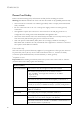
APPENDIX A TROUBLESHOOTING Diagnosing Switch Indicators This switch can be easily monitored through panel indicators to identify problems.The table below describes common problems you may encounter and possible solutions. Table A-1 Diagnosing Switch Indicators Symptom Possible Cause Action Power indicator does not light up after power on. Power outlet, power cord, or internal power supply may be defective. • Check the power outlet by plugging in another device that is functioning properly.
TROUBLESHOOTING Table A-1 Diagnosing Switch Indicators Symptom Possible Cause Action Ethernet port Link indicator does not light up after making a connection. Network cable or Ethernet device attached to this port may be defective. • Verify that the switch and attached device are powered on. • Be sure an Ethernet cable is plugged into both the switch and attached device. • Verify that the proper cable type is used and its length does not exceed specified limits.
POWER AND COOLING PROBLEMS Power and Cooling Problems If the power indicator does not turn on when the power cord is plugged in, you may have a problem with the power outlet, power cord, or internal power supply. However, if the unit powers off after running for a while, check for loose power connections, power losses or surges at the power outlet, and verify that the fans on the unit are unobstructed and running prior to shutdown.
TROUBLESHOOTING Note: The switch can accept up to four simultaneous Telnet sessions. If the maximum number of sessions already exists, an additional Telnet connection will not be able to log into the system.
APPENDIX B CABLES Twisted-Pair Cable and Pin Assignments For 10BASE-T/100BASE-TX connections, a twisted-pair cable must have two pairs of wires. For 1000BASE-T connections the twisted-pair cable must have four pairs of wires. Each wire pair is identified by two different colors. For example, one wire might be green and the other, green with white stripes. Also, an RJ-45 connector must be attached to both ends of the cable.
CABLES 10BASE-T/100BASE-TX Pin Assignments Use unshielded twisted-pair (UTP) or shielded twisted-pair (STP) cable for RJ-45 connections: 100-ohm Category 3 or better cable for 10 Mbps connections, or 100-ohm Category 5 or better cable for 100 Mbps connections.
TWISTED-PAIR CABLE AND PIN ASSIGNMENTS Straight-Through Wiring If the twisted-pair cable is to join two ports and only one of the ports has an internal crossover (MDI-X), the two pairs of wires must be straightthrough. (When auto-negotiation is enabled for any RJ-45 port on this switch, you can use either straight-through or crossover cable to connect to any device type.) You must connect all four wire pairs as shown in the following diagram to support Gigabit Ethernet connections.
CABLES Crossover Wiring If the twisted-pair cable is to join two ports and either both ports are labeled with an “X” (indicating MDI-X) or neither port is labeled with an “X” (which indicates MDI), a crossover must be implemented in the wiring. (When auto-negotiation is enabled for any RJ-45 port on this switch, you can use either straight-through or crossover cable to connect to any device type.) You must connect all four wire pairs as shown in the following diagram to support Gigabit Ethernet connections.
TWISTED-PAIR CABLE AND PIN ASSIGNMENTS 1000BASE-T Pin Assignments 1000BASE-T ports switch support automatic MDI/MDI-X operation, so you can use straight-through cables for all network connections to PCs or servers, or to other switches or hubs. The table below shows the 1000BASE-T MDI and MDI-X port pinouts. These ports require that all four pairs of wires be connected. Note that for 1000BASE-T operation, all four pairs of wires are used for both transmit and receive.
CABLES 1000BASE-T Cable Requirements All Category 5 UTP cables that are used for 100BASE-TX connections should also work for 1000BASE-T, providing that all four wire pairs are connected. However, it is recommended that for all critical connections, or any new cable installations, Category 5e (enhanced Category 5) or Category 6 cable should be used. The Category 5e specification includes test parameters that are only recommendations for Category 5.
FIBER STANDARDS Fiber Standards The current TIA (Telecommunications Industry Association) 568-A specification on optical fiber cabling consists of one recognized cable type for horizontal subsystems and two cable types for backbone subsystems. Horizontal 62.5/125 micron multimode (two fibers per outlet). Backbone 62.5/125 micron multimode or single mode. TIA 568-B will allow the use of 50/125 micron multimode optical fiber in both the horizontal and backbone in addition to the types listed above.
CABLES RJ-21 Port Pin Assignments The RJ-21 ports are designed to aggregate 24 POTS/VDSL lines, although only 16 lines are implemented for this switch. Each wire pair must be attached to the RJ-21 connector in a specific orientation detailed below. The following tables show the pin assignments.
CONSOLE PORT PIN ASSIGNMENTS Console Port Pin Assignments The DB-9 serial port on the switch’s front panel is used to connect to the switch for out-of-band console configuration. The on-board commandline configuration program can be accessed from a terminal or a PC running a terminal emulation program. The pin assignments used to connect to the serial port are provided in the following tables.
CABLES Console Port to 9-Pin DTE Port on PC Table B-6 Console Port to 9-Pin DTE Port on PC Switch’s 9-Pin Serial Port Null Modem PC’s 9-Pin DTE Port 2 RXD <--------- TXD ------------> 3 TXD 3 TXD ----------- RXD ----------> 2 RXD 5 SGND <----------- SGND ----------> 5 SGND No other pins are used.
APPENDIX C SPECIFICATIONS Physical Characteristics VDSL Specifications Band Plan: Up to 6 bands Signal Bandwidth: 25 kHz to 30MHz Data Rate: Up to 100 Mbps / 100 Mbps (Downstream/Upstream) Range: Up to 200 meters (656 ft) Optional Band: US0 from 4~25 kHz (low end) to 138~276 kHz (high end) Multi-Carrier-Modulation (MCM) - DMT modulation Interleaving: general convolution Tone Spacing: 8.6 kHz Upstream Power Back-off (UPBO) Compliance: ETSI 101/270, ANSI T1E1.4 and ITU-T G.993.
PHYSICAL CHARACTERISTICS Buffer Architecture 16 Mbytes Aggregate Bandwidth 8.8 Gbps Switching Database 8K MAC address entries LEDs System: Power, Diag, Fault Port: Link/Act Weight 2.92 kg (6.44 lb) Size 44.0 x 35.2 x 6.6 cm (17.4 x 13.9 x 2.6 in.) Temperature Operating: 0 to 50 °C (32 to 122 °F) Storage: -40 to 70 °C (-40 to 158 °F) Humidity Operating: 5% to 90% Power Supply 100 to 240 VAC, 50 to 60 Hz Power Consumption 61.68 Watts maximum Heat Dissipation 211 BTU/hr maximum Maximum Current 0.
SPECIFICATIONS Switch Features Forwarding Mode Store-and-forward Throughput Layer 2: wire speed Flow Control Full Duplex: IEEE 802.
STANDARDS Standards Ethernet Standards IEEE 802.3-2005 Ethernet Access Ethernet, Fast Ethernet, Gigabit Ethernet Link Aggregation Control Protocol (LACP) Full-duplex flow control (ISO/IEC 8802-3) IEEE 802.1D Spanning Tree Protocol IEEE 802.1w Rapid Spanning Tree Protocol IEEE 802.1s Multiple Spanning Tree Protocol IEEE 802.1p priority tags IEEE 802.3ac VLAN tagging IEEE 802.1Q Virtual LAN IEEE 802.1v Protocol-based VLANs VDSL Standards ANSI T1E1.4 Part 1 - VDSL Interface ITU-T G.993.1 - VDSL ITU-T G.993.
SPECIFICATIONS Safety CSA/CUS (CSA 22.2.
COMPLIANCES C-6
APPENDIX D ORDERING INFORMATION Table D-1 TigerAccess EE Products and Accessories Product Number Description SMC7816M/VSW 16-Port VDSL2 Switch with 2 combo Gigabit Ethernet uplink ports (RJ-45/SFP) and 1 dedicated Fast Ethernet management port (RJ-45) SMC7800A/VCP Ethernet-over-VDSL2 CPE with 1 VDSL line port, 1 POTS phone port, and 1 Fast Ethernet port SMCBGSLCX1 1-port 1000BASE-SX Small Form Pluggable (SFP) mini-GBIC transceiver SMCBGLLCX1 1-port 1000BASE-LX Small Form Pluggable (SFP) mini-GBIC t
ORDERING INFORMATION D-2
GLOSSARY 10BASE-T IEEE 802.3 specification for 10 Mbps Ethernet over two pairs of Category 3, 4, or 5 UTP cable. 100BASE-TX IEEE 802.3u specification for 100 Mbps Fast Ethernet over two pairs of Category 5 UTP cable. 1000BASE-LX IEEE 802.3z specification for Gigabit Ethernet over two strands of 50/ 125, 62.5/125 or 9/125 micron core fiber cable. 1000BASE-SX IEEE 802.3z specification for Gigabit Ethernet over two strands of 50/ 125 or 62.5/125 micron core fiber cable. 1000BASE-T IEEE 802.
GLOSSARY Bandwidth The difference between the highest and lowest frequencies available for network signals. Also synonymous with wire speed, the actual speed of the data transmission along the cable. Collision A condition in which packets transmitted over the cable interfere with each other. Their interference makes both signals unintelligible. Collision Domain Single CSMA/CD LAN segment.
GLOSSARY Fast Ethernet A 100 Mbps network communication system based on Ethernet and the CSMA/CD access method. Fibre To The Home (FTTH) Network where an optical fibre runs from the telephone switch to the subscriber's premises or home. Full Duplex Transmission method that allows two network devices to transmit and receive concurrently, effectively doubling the bandwidth of that link. Gigabit Ethernet A 1000 Mbps network communication system based on Ethernet and the CSMA/CD access method.
GLOSSARY IEEE 802.3x Defines Ethernet frame start/stop requests and timers used for flow control on full-duplex links. (Now incorporated in IEEE 802.3-2005.) IEEE 802.3z Defines CSMA/CD access method and physical layer specifications for 1000BASE Gigabit Ethernet. (Now incorporated in IEEE 802.3-2005.) LAN Segment Separate LAN or collision domain. Layer 2 Data Link layer in the ISO 7-Layer Data Communications Protocol.
GLOSSARY Media Access Control (MAC) A portion of the networking protocol that governs access to the transmission medium, facilitating the exchange of data between network nodes. Modal Bandwidth Bandwidth for multimode fiber is referred to as modal bandwidth because it varies with the modal field (or core diameter) of the fiber. Modal bandwidth is specified in units of MHz per km, which indicates the amount of bandwidth supported by the fiber for a one km distance.
GLOSSARY TIA Telecommunications Industry Association Transmission Control Protocol/Internet Protocol (TCP/IP) Protocol suite that includes TCP as the primary transport protocol, and IP as the network layer protocol. User Datagram Protocol (UDP) UDP provides a datagram mode for packet-switched communications. It uses IP as the underlying transport mechanism to provide access to IP-like services.
GLOSSARY Virtual LAN (VLAN) A Virtual LAN is a collection of network nodes that share the same collision domain regardless of their physical location or connection point in the network. A VLAN serves as a logical workgroup with no physical barriers, allowing users to share information and resources as though located on the same LAN.
GLOSSARY Glossary-8
INDEX Numerics 10 Mbps connectivity rules 4-9 100 Mbps connectivity rules 4-9 1000 Mbps connectivity rules 4-8 1000BASE-LX connections 4-6 fiber cable lengths 4-9 1000BASE-SX connections 4-6 fiber cable lengths 4-8 1000BASE-T cable lengths 4-8 1000BASE-X connections 4-6 1000BASE-ZX connections 4-6 fiber cable lengths 4-9 100BASE-TX cable lengths 4-9 10BASE-T cable lengths 4-9 A accessories, ordering D-1 adhesive feet, attaching 3-7 air flow requirements 3-3 applications Internet connections 2-2 remote conn
INDEX H M hardware components 1-5 hardware, basic description 1-5 management agent 1-4 features 1-12, C-3 SNMP 1-4 management port, functional description 1-7 MIB support C-4 mounting the switch on a desktop or shelf 3-7 multimode fiber optic cables 4-6 I IEEE 802.3 Ethernet 1-12 IEEE 802.3-2005 1-12 IEEE 802.3u Fast Ethernet 1-12 IEEE 802.
INDEX rubber foot pads, attaching 3-7 S SC port connections 4-6 screws for rack mounting 3-5 SFP slots 1-7 supported transceivers 1-7 single-mode fiber optic cables 4-6 site requirements 3-2 selelction 3-2 SNMP agent 1-4 specifications compliances C-4 environmental C-2 management features C-3 physical C-1 switching features C-3 standards compliance C-4 IEEE C-4 status LEDs 1-8 switch architecture 1-4 switching, introduction to 2-1 T troubleshooting in-band access A-3 power and cooling problems A-3 switch
INDEX Index-4
FOR TECHNICAL SUPPORT, CALL: From U.S.A. and Canada (24 hours a day, 7 days a week) (800) SMC-4-YOU; (949) 679-8000; Fax: (949) 679-1481 From Europe: Contact details can be found on www.smc-europe.com or www.smc.com INTERNET E-mail addresses: techsupport@smc.com european.techsupport@smc-europe.com Driver updates: http://www.smc.com/index.cfm?action=tech_support_drivers_downloads World Wide Web: http://www.smc.com http://www.smc-europe.com FOR LITERATURE OR ADVERTISING RESPONSE, CALL: U.S.A.