AUTO SETUP MODULE COLOR DISPLAY OPERATING MANUAL LINK ELECTRIC & SAFETY CONTROL COMPANY 444 McNALLY DRIVE, NASHVILLE TN 37211 PH (615)-833-4168 FAX (615)-834-1984 OmniLink 5000 System 5000 Press Control
Table of Contents Section 1 Introduction . . . . . . . . . . . . . . . . . . . . . . . . . . . . . . . . . . . . . . . . . . . . . . . . . . . . . . . . . . Section 1.1 Counterbalance Control . . . . . . . . . . . . . . . . . . . . . . . . . . . . . . . . . . . . . . . . . . . . . . Section 1.2 Cushion Control . . . . . . . . . . . . . . . . . . . . . . . . . . . . . . . . . . . . . . . . . . . . . . . . . . . . Section 1.3 Shut Height Control . . . . . . . . . . . . . . . . . . . . . . . . . . . . . . . .
Section 4. Configuration . . . . . . . . . . . . . . . . . . . . . . . . . . . . . . . . . . . . . . . . . . . . . . . . . . . . . . . . . 4.1 Section 4.1 Setting up the OmniLink 5000 for the Auto-Setup Module . . . . . . . . . . . . . . . . . . 4.1 Section 4.2 Configuring the Auto-Setup board . . . . . . . . . . . . . . . . . . . . . . . . . . . . . . . . . . . . . . . . 4.2 Section 4.2.1 Configuring Counterbalance, Cushion, and Hydraulic Overload Modules . . . 4.2 Section 4.2.
Appendix F Specifications . . . . . . . . . . . . . . . . . . . . . . . . . . . . . . . . . . . . . . . . . . . . . . . . . . . . . . . . . Section F.1 5000-10A Pressure Control Board . . . . . . . . . . . . . . . . . . . . . . . . . . . . . . . . . . . . . . Section F.2 5000-10B Linear Shut Height Control Board . . . . . . . . . . . . . . . . . . . . . . . . . . . . . Section F.3 5000-10C Rotary Shut Height Control Board . . . . . . . . . . . . . . . . . . . . . . . . . . . . .
April 17, 2000 Man ual Versio n 1.
Section 1 Introduction The 5000-10 Auto-Setup Module (ASM) allows the OmniLink 5000 Press and Automation control to set up press shut height, counterbalance air pressure, cushion air pressures, and hydraulic overload pressure settings automatically when jobs are recalled from memory. It consists of a base 5000-10 microprocessor board that installs in the OmniLink extended card rack, and additional modules that may be mounted on the base board to provide pressure or shut height adjustment functions.
Section 1.3 Shut Height Control When a linear or rotary shut height control module is provided, the OmniLink 5000 can provide accurate, repeatable shut height adjustment on presses that are in reasonable mechanical condition, enhancing parts quality and reducing setup time. This system uses the existing slide motor starter. Section 1.
Section 2 Parameter Entry and Access Control Section 2.1 Parameter Entry Throughout the OmniLink control, a fairly standard form of data entry is employed. When data entry is allowed, an “editing cursor” will appear on the screen. This cursor can typically be moved from parameter to parameter on the screen with the up, down, left, and right arrow keys. The topmost softkey is used to select the parameter for editing and can change description depending on the parameter selected. Section 2.1.
Figure 2.1: Example Text Entry c) The fist character of the text is highlighted with the text cursor. The CURSOR LEFT and CURSOR RIGHT softkeys will move this cursor. d) Use the left and right arrow keys to point to the letter desired in the letter box next to the text being edited. This box will just appear above or just below the text to be edited depending on where it is in the screen. Hit the SELECT LETTER softkey to place that letter at the text cursor.
Section 2.2 Access Control The OmniLink control has several parameters or operations that have limited access. In regards to the auto setup module the ability to perform the actions of resetting faults or changing limits must be restricted to certain personnel. The OmniLink control provides several means to limit access to these parameters or operations. These parameters and operations are called restricted items.
The example above can be taken one additional step if two press operators are given different user names and different passwords. One operator can be assigned the ability to change auto setup limits in addition to the ability to reset faults, while the other operator is not assigned the ability to change the limits. Section 2.2.3 Password Only Mode The “Password Only” mode allows for sixteen users. Each user can be assigned access to some or all of the restricted items.
When operating in the Key Only mode the key switch is the only means available to access the restricted items. All restricted items are accessible when the RUN/PROG key switch is switched to the PROG position. When operating in the “Key or Password” mode, the key switch is one of the means available to access the restricted items. All restricted items are accessible when the RUN/PROG key switch is switched to the PROG position.
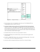
Step A: Select the restricted item. In the example shown in Figure 2.2 the restricted item is Slide Adjust #1 setpoint. Once the parameter is selected then Softkey # 1, the upper vertical softkey (Softkey # 1 is highlighted in Figure 2.2) , will display the legend “SELECT”. Step B: A list of users that have access to this restricted item will appear. In the example shown in Figure 2.2 only User Number One, User Number Two, and User Number Five have access to this restricted parameter.
Section 3. Installation Section 3.1 Auto-Setup Module Installation The 5000-10 Auto-Setup Module (ASM) installs in the OmniLink 5000 extended card rack. Figure 3.1 shows the location of the ASM in the last slot of the extended card rack. To remove the module, loosen the knurled screws at the top and bottom of the board and use them to pull the board straight out of the rack.
or AS4. The plug in terminals on the modules should stick out of the faceplate of the base card. April 17, 2000 Man ual Versio n 1.0 3.
Section 3.2 Valve Systems Counterbalance and cushion systems are very similar in the way they are controlled. Three basic integrated valve configurations are available from Link to be used with the OmniLink 5000 ASM. For clarity in the following sections, these valve configurations are defined here. Type “A” An integrated Fill/Dump Valve as shown in Figure 3.2. This valve has the advantage of simple straight through piping with all pilot pressures run internally and is easily mounted.
Type “C” An integrated Fill/Dump valve with a manual regulator, check valve, and LOX valve, and a four-way valve that selects whether the pressure is set by the automatic system or the manual regulator as shown in Figure 3.4 for cushion and counterbalance adjustment. Unlike the type “B” valve, the manual regulator can be set to any allowable pressure without interfering with automatic pressure adjustment- it does not have to be a minimum pressure.
For automatic control, the pressure regulator and check valve are replaced with an air valve system. Figures 3.6 and 3.7 illustrate systems using the Type “A” and Type “C” valves described in section 3.2. In all cases a pressure transducer is used to monitor the air pressure. April 17, 2000 Figure 3.6: Auto-Counterbalance with Type “A” Integrated Valve. Figure 3.7: Auto-Counterbalance with Type “C” Integrated Valve. Man ual Versio n 1.0 3.
Section 3.3.1 Counterbalance Pressure Transducer Mounting The system uses an automatic method of control in which the fill valve or dump valve is energized to raise or lower the pressure of the system and a pressure transducer is used to “tell” the ASM what pressure is in the system. The pressure transducer is constantly monitored to verify that the system is at the proper pressure. When filling or dumping air into or out of the counterbalance, the transducer tells the system when to stop.
Section 3.3.2 Counterbalance Air Valve System Mounting The mounting location of the valve system is not critical. Consideration should be given, however, to ease of maintenance, plumbing, and wiring when choosing the mounting location. Also note that sometimes the check valve in the original system may be up at the surge tank itself. The check valve in the original system must be removed for the automatic system to work properly. Section 3.3.3 Counterbalance System Wiring Refer to Appendix B, Figure B.
Section 3.4.1 Cushion Pressure Transducer Mounting The system uses a method of control in which the fill valve or dump valve is energized to raise or lower the pressure of the system. The pressure transducer tells the system when it has reached the proper pressure. Because air pressure drops occur across air lines when filling or dumping, proper placement of the pressure transducer is very important for correct operation of the system.
control came configured for a cushion adjust system, then a wiring diagram should have been provided as part of the documentation package. Section 3.5 Hydraulic Overload System Installation Some press hydraulic overload systems use an air pressure to set up a much greater hydraulic pressure through an air pump to control the trip point (tonnage) at which the hydraulic overload cylinder will dump.
c) The slide should travel no more than 1 inch per turn of the resolver. d) The cable from the resolver to the OmniLink 5000 should not be run with any high voltage wiring (i.e. 120/240 VAC). In fact, this cable should be run in its own shielded conduit. It is not necessary to know the exact gear ratio of slide travel to resolver turns - only that conditions “b” and “c” are met. The resolver may rotate in either direction relative to slide travel (i.e.
b) It may be necessary to order a transducer longer than the slide adjustment range because of mounting limitations. c) Ferromagnetic material (a material readily magnetized - such as iron or steel) should be no closer than .25" from the magnet or the rod end. This includes ferrous screws! Non-ferrous metals such as aluminum, brass, and non-magnetic stainless can be in direct contact with the magnet or rod end. d) Transducers longer than 30" may need special supports and split magnets.
Section 4. Configuration After the ASM is installed (see section 3.1), it must be configured to work with the press. Configuration consists of several steps that depend on the options selected for the ASM. NOTE! An access code is required to reach the configuration menus of the OmniLink 5000 press control. The code is provided separately from this manual for administrative control. WARNING! Only qualified employees who are authorized by the user should configure the automatic set-up module.
Section 4.2 Configuring the Auto-Setup board The ASM must be configured for the each shut height and pressure module that is installed on it. The configuration necessary depends on the particular kind of module. Section 4.2.1 Configuring Counterbalance, Cushion, and Hydraulic Overload Modules Counterbalances and cushions are conceptually very similar and use essentially the same control techniques.
There are several parameters that must be configured in this screen. The editing cursor indicates which parameter is currently selected. Softkey 1 (the uppermost vertical softkey) will change its description based on the parameter and, when pressed, allows the currently selected parameter to be changed. The up and down arrow keys move the editing cursor from one parameter to another. See Appendix A for examples of setting up each kind of system.
For cushions this should be the maximum operating pressure specified by the cushion manufacturer. For hydraulic overloads this value should be the pressure specified by the press manufacturer for rated tonnage operation. Min. Pressure This value should be set to the minimum operating pressure at which you will operate your counterbalance, cushion, or hydraulic overload. For counterbalances, this value is the pressure that balances the slide with no tooling and cannot be set below 5 psi.
are pounds (lbs), kilograms (Kgs), tons, and metric tons (Mtons). Note that the display unit can be changed at any time and is independent of the units that the maximum and minimum die weight are using. If a job was stored in tons, and this unit is changed to pounds, the stored job will still be correct. For example, if 2 tons were stored for a job and the display unit is changed to pounds, when the job is recalled it will be set to 4000 pounds. Max.
choices are pounds (lbs), kilograms (Kgs), tons, and metric tons (Mtons). Note that the display unit can be changed at any time and is independent of the units used for minimum and maximum trip point. If a job was stored in tons, and this unit is changed to pounds, the stored job will still be correct. For example, if 2 tons were stored for a job and the display unit is changed to pounds, when the job is recalled it will be set to 4000 pounds.
Table 4.2: Servo-Valve Control Types Wilkerson ER1 Series 0-90psi 0-10V 5 SMC ITV2050-31T2S4 0-130psi 0-10V 6 Section 4.2.2 Configuring Slide Adjust Modules To get to the configuration screen for slide adjust modules: a) Go to the “Auto Sets” screen. This screen is reached by pressing the “AUTO SETS” softkey in the Main Menu or Press Control screen. b) With the RUN/PROG key switch in the PROG position, press the “CONFIGURE” softkey and enter the configuration code.
parameter is currently selected. Softkey 1 (the uppermost vertical softkey) will change its description based on the parameter and, when pressed, allows the currently selected parameter to be changed. The up and down arrow keys move the editing cursor from one parameter to another. See Appendix A for examples of setting up each kind of system. The features of this screen are: Help The “Help” box at the bottom of the screen changes depending on the parameter that the editing cursor is currently on.
Upper Limit This value is an electronic upper limit for the slide adjust system that acts as a backup for the mechanical up limit switch. The automatic shut height system will not adjust the shut height above this value, which should be set just below where the mechanical up limit switch open up. Lower Limit This value is an electronic lower limit for the slide adjust system that acts as a backup for the mechanical down limit switch.
Lock Time Most slide adjust systems now use an integrated brake built in to the slide adjust motor that automatically locks the system down when the slide adjust motor is not on. “Lock Time” is used only for slide adjust systems that have a separate locking system that must be disengaged before the slide adjust motor is engaged.
transducer is used) must now be set. This value is listed on the transducer model plate. Press the “CONTINUE SLIDE CAL.” softkey to continue the calibration process or “EXIT” to return to slide configuration. f) Finally, the “Calibration Point” must be set. The slide should be taken to bottom dead center (180 degrees) and the shut height should be measured. Without moving the slide that measurement should be entered here. This tells the system what the current shut height is. Press the “CONTINUE SLIDE CAL.
screen of Figure 4.3. NOTE: It is absolutely critical to set the upper and lower limits correctly before calibrating a rotary slide adjust system. The calibration process uses this information to map the turns from the dual resolver into the measurement space of the slide. If the upper and lower limits are not set correctly, the system may fail to calibrate! b) Press the “CALIBRATE SLIDE” softkey in the slide configuration screen of Figure 4.3.
Press the “CONTINUE SLIDE CAL.” softkey to continue the calibration process or “EXIT” to return to slide configuration. g) Finally, the lower calibration point must be set. Use the “JOG UP” and “JOG DOWN” softkeys to take the slide near the bottom of the adjustment range. The slide should be slightly higher than the lower limit entered on the slide configuration screen.
April 17, 2000 Man ual Versio n 1.0 4.
Section 5 Operation The purpose of the Auto-Setup module is to allow automatic adjustment of such press systems as air counterbalances, air cushions, air operated hydraulic overloads, and slide adjust systems to greatly reduce setup time for different jobs, and to help ensure that these systems are adjusted correctly for different jobs. All operation of auto-setup functions, other than automatic adjustments to previously stored values when the OmniLink 5000 recalls a job, start from the Auto-Sets screen.
for the shut height setpoint. See section 6 for an explanation of all status messages for the various sub-systems. c) Each configured sub-system has a fault message. Under normal conditions, this fault should read “None”. See section 6 for an explanation of all fault messages for the various sub-systems. d) Air pressure controlled sub-systems (counterbalances, cushions, and hydraulic overload) display the current actual pressure for that system in large numbers for easy visibility.
“CONFIGURE” Allows the individual options such as counterbalance, cushion, and slide adjust modules to be configured during initial installation of the system and will not be used for production operation setup. Note that this key is only available when the RUN/PROG keyed switch is in the PROG position. “JOG UP” Press this softkey to move the slide up. A momentary push will “pulse” the slide up once for fine control.
rotary transducer mounted on the slide system of the press. The units for the position can be in inches or millimeters depending on the configuration. See section 4.2.2 for details. Fault If the slide adjust system detects an error it will be reported on this line. A fault occurs when a hardware or firmware problem is diagnosed by the system. See section 6 for fault messages and their meanings. Status The current status of the slide adjust system.
the slide adjust screen or when a stored job is recalled and the system is “ON”. Note that the “AUTO ADJUST” key will only appear when the slide adjust switch is ON and the editing cursor is on the slide adjust setpoint of a slide adjust system. An auto adjust sequence always approaches the slide setpoint from above. For instance, if the current position is 10.000 and the slide setpoint is 12.000, the auto adjust sequence might take the slide first to 12.015, then back to 12.
Section 5.1.3 Manual Slide Movement As noted in the section explaining the softkeys in the slide screen, the slide may be manually moved by pressing the “JOG UP” and “JOG DN” softkeys. Note that the jog keys will only appear when the editing cursor is on a slide adjust setpoint. These keys will work regardless of whether the slide system is on, off, or in manual mode. Note, however, that these keys will not override the mechanical up and down limit switches in the slide.
setpoint for a previously stored job when that job setup is recalled from memory and the air system is “ON”. This number can be set in pounds, kilograms, tons, or metric tons depending on the configuration as detailed in section 4.2.1. Press Trip Set For hydraulic overloads only, the desired trip point to be set by the air system. This number may be changed by manual operator entry when the operator has access via key or user code depending on the configuration of the system as detailed in section 2.
Pressure can be set in one of two ways. First, if the air system was correctly configured, the desired force which the pressure is to create can be entered in the “Force Setpoint” row on the air pressure screen. Second, if preferred, the desired air pressure in psi may be entered into the “pressure setpoint” row. For counterbalances, the “Die Weight Set” is the weight of the upper die that attaches to the slide.
“Waiting for Top”. When the press does reach the top and all other necessary conditions are satisfied, the slide will go to the slide setpoint. d) If a job is recalled when the slide adjust switch is not on, the slide adjust system will display a status of “Waiting S/A Switch”. When the slide adjust switch is turned on and all other necessary conditions are satisfied, the slide will go to the slide setpoint.
Section 6 Diagnostics - Fault and Status Messages When the press control screen reports a stop condition that indicates the auto-setup board asserted or is asserting a stop signal, the “Auto-Sets” screen module status and the individual sub-systems status line will give additional information. Section 6.1 Main Module Messages All Conditions OK General Module status is ok. This does not mean that the individual sub systems such as shut height control, counterbalance, and cushion control are ok.
Unable to Fill The system was unable to make progress when trying to raise the air pressure. This could be a bad connection to the fill valve, a failed fill valve, or no plant air pressure. Probably the most common cause would be a bad air leak in the system. Unable to Dump The system was unable to make progress when trying to lower the air pressure. Probably a bad connection to the dump valve or a failed dump valve. Max. Press.
Ctr-Bal Vented -Stop A pressure setpoint of 0 was entered for a counterbalance. The dump valve is left open in this condition. Unlike a cushion, this is considered a stop condition. Hyd Overload Tripped The hydraulic overload operation screen will display this message when the press hydraulic overload system is tripped. Waiting for Top The hydraulic overload system is waiting for the press to reach the top of the stroke before it adjusts the hydraulic overload setting.
a hardware failure of the relay. Lock Relay Shorted The “Lock” solid state relay on the slide adjust module failed shorted. Indicates a hardware failure of the relay. Transducer Fail For linear slide systems, indicates that the linear transducer is not sending information to the slide adjust module. This may be a cable problem, unplugged connector, failed power supply, failed transducer, or option board (5000-10B) problem.
Min Position Reached The slide has gone as low as the min position programmed in the configuration menu and will not be allowed to go lower. Moving Up The slide is moving up. Moving Down The slide is moving down. System Off The slide adjust system is turned off. The slide can still be manually moved by using the jog up and jog down buttons. The slide position will still be shown if the position transducer is still functioning correctly.
Appendix A Configuration Examples This section of the manual will go though an example setup of each kind of system on a “typical” press. Each example assumes that the hardware installation has been completed and the system is ready for configuration. The following examples assume the access system is using “Key Only” mode as described in section 2. Other modes may require entering a user code to change certain parameters. Section A.
Note that units to the right of the number are also an editable parameter. When the editing cursor is placed on the Max Die Weight units, we can press the “CHANGE UNIT” softkey to get a list of supported units. The units can be pounds, kilograms, tons, or metric tons. We are using pounds. Note that the units for minimum and maximum die weight will always be the same, but will not necessarily be the same as the “Display Weight As” units.
Using the arrow keys, we move the cursor to the “Transducer Type” line. Looking at table 4.1, we see that the transducer type for any model pressure transducer with a 250 psi pressure range and a 4 to 20 ma output is “Type 3”. We hit the “CHANGE TYPE” softkey and select Type 3 from the list that appears. When the proper type is selected, the “Air Pressure” line should change to read the pressure currently in the cushion system. Next we move the editing cursor to the “Maximum Pressure” line.
The pressure transducer installed on the system is a Setra model C206 that has a pressure range of 0 to 250 psi and an output of 4 to 20 ma. An SMC ITV2050-31T2S4 servo-valve will be used to control the pressure. This valve is 0-130 psi with a 0-10V input. Now we go to the “Auto Sets” screen and with the RUN/PROG switch in PROG hit the “CONFIGURE” softkey. After typing the configuration code, we press the “CONFIGURE AIR” softkey.
Finally, we go back to the “Mode” line and use the “CHANGE MODE” softkey to toggle the mode to “ON”. The “Auto Sets” operation screen can now be used to set the air pressure or trip tonnage. See section 5.2 for operation details. Section A.4 Example Linear Slide Adjust Configuration This example assumes the linear slide adjust system has been wired to the option board at “SS1". First, some information needs to be gathered. A GEMCO 952 series linear transducer is mounted on the press slide.
will be flawed because clearances will not be taken up by the counterbalance. Now we press the “CALIBRATE SLIDE” softkey to perform the actual slide calibration as described in section 4.2.2.1 using the wire speed from the transducer nameplate (9.219 in this example) and an orientation of 0. After calibration, the “Present Position” field in the slide configuration screen should display the number we just entered for the calibration position to the nearest thousandth. In other words, if we had entered 14.
Now it is time to hit the “AUTO ADJUST” softkey. The slide moves up past 14.000 (the slide setpoint we entered in the operation screen) and stops momentarily at 14.025. It then comes back down and stops at 13.996. The “Pulse Distance” value is set too high. What should have happened is that the slide would go over 14.000, come back down to a position just over 14.000 - say 14.003 - and then pulse into position at 14.000. Since we went under our setpoint by .004 inches, we change the “Pulse Distance” to .
Before calibrating the slide, we MUST make sure the slide is properly counterbalanced, if a counterbalance is used on our press. If the slide is not properly counterbalanced, the slide calibration will be flawed because clearances will not be taken up by the counterbalance. Now we press the “CALIBRATE SLIDE” softkey to perform the actual slide calibration as described in section 4.2.2.2. We need to know the resolver turns (100) for calibration.
“.04" sec. Repeating the test, we find that it now takes 1 to 2 pulses to move .001 inch - an acceptable value. Now it is time to hit the “AUTO ADJUST” softkey. The slide moves up past 14.000 (the slide setpoint we entered in the operation screen) and stops momentarily at 14.025. It then comes back down and stops at 13.996. The “Pulse Distance” value is set too high. What should have happened is that the slide would go over 14.000, come back down to a position just over 14.000 - say 14.
Appendix B Typical Wiring Diagrams Figure B.1: Typical Counterbalance Wiring Diagram. April 17, 2000 Man ual Versio n 1.0 B.
Figure B.2: Typical Cushion Wiring Diagram. April 17, 2000 Man ual Versio n 1.0 B.
Figure B.3: Conceptual Dual Resolver Mounting. April 17, 2000 Man ual Versio n 1.0 B.
Figure B.4: Typical AMCI Dual Resolver Wiring Diagram. April 17, 2000 Man ual Versio n 1.0 B.
Figure B.5: Typical GEMCO Dual Resolver Wiring Diagram April 17, 2000 Man ual Versio n 1.0 B.
Figure B.6: Conceptual Linear Transducer Mounting April 17, 2000 Man ual Versio n 1.0 B.
Figure B.7: Typical GEMCO Linear Transducer Wiring April 17, 2000 Man ual Versio n 1.0 B.
Figure B.8: Typical MTS Temposonics II Linear Transducer Wiring April 17, 2000 Man ual Versio n 1.0 B.
Figure B.9: Typical Slide Motor Starter Wiring With Auxiliary Contactor Figure B.10: Typical Slide Motor Starter Wiring Without Auxiliary Contactor Figure B.11: Typical Slide Air Motor Solenoid Wiring April 17, 2000 Man ual Versio n 1.0 B.
April 17, 2000 Man ual Versio n 1.0 B.
Appendix C Installation Of OmniLink 5000 Firmware Firmware for the OmniLink 5000 press control is contained on two integrated circuits. Please follow the instructions listed below for replacing the OmniLink 5000 firmware. 1) Remove all power from the OmniLink 5000 press control. Insure that the power to the OmniLink card rack and the OmniLink Operator Interface terminal has been removed. 2) Remove the logic board from the card rack.
April 17, 2000 Man ual Versio n 1.0 C.
Appendix D Lockout Procedure For Air Controlled Systems Section D.1 General Lockout Considerations The OmniLink 5000 auto-setup card automatically controls pressures in cushions and counterbalances. Because of this there are special considerations to keep in mind when locking an air system out (at 0 pressure). Note that cushions can be vented to zero pressure and the press will be allowed to run.
Section D.3 Valve Type “B” Lockout Procedure The type “B” valve has a manual regulator in parallel with the automatic section that prevents the pressure it is controlling from going below a minimum. To lock this valve out: 1) Set the pressure setpoint for the air system to 0 psi. At this point the manual regulator will try to fill the system while the automatic section tries to dump. 2) Use the LOX valve (integrated into this type of valve) to dump the system and lock out the manual section.
Appendix E Configuration Sheets Section E.1 Air System Calibration Sheets Air Pressure Configuration Air Pressure Configuration Slot #1 Board ___________________________ Name ___________________________ Transducer Type __________ Max. Pressure __________ Min. Pressure __________ Max. Force __________ Min.
Air Pressure Configuration Air Pressure Configuration Slot #4 Board ___________________________ Name ___________________________ Transducer Type __________ Max. Pressure __________ Min. Pressure __________ Max. Force __________ Min. Force __________ Fault Time __________ Tolerance __________ Air Pressure Configuration Air Pressure Configuration Slot #7 Board 0-10 Volt Out Name ___________________________ Transducer Type __________ Valve Type __________ Max. Pressure __________ Min. Pressure __________ Max.
Section E.
Rotary Transducer Slide Configuration Slide Configuration Slot #1 Board Rotary Transducer Name ___________________ Upper Limit __________ Lower Limit __________ Tolerance __________ Pulse Distance __________ Pulse Time __________ Lock Time __________ Resolver Turns __________ Rotary Transducer Slide Configuration Slide Configuration Slot #2 Board Rotary Transducer Name ___________________ Upper Limit __________ Lower Limit __________ Tolerance __________ Pulse Distance __________ Pulse Time __________ Lock
Appendix F Specifications Section F.1 5000-10A Pressure Control Board AC Output Relays: Voltage: Current: Fuse: Section F.2 5000-10B Linear Shut Height Control Board AC Output Relays: Voltage: Current: Fuse: Section F.3 120VAC 1Amp Continuous 20 Amp 16ms 5 Amp 75ms 2 Amp Fast-Blow Picofuse 5000-10C Rotary Shut Height Control Board AC Output Relays: Voltage: Current: Fuse: April 17, 2000 120VAC 1Amp Continuous 20 Amp 16ms 5 Amp 75ms 2 Amp Fast-Blow Picofuse Man ual Versio n 1.