EZ Switch 10/100/1000 User Guide From SMC’s EZ line of low-cost workgroup LAN solutions 38 Tesla Irvine, CA 92618 Phone: (949) 679-8000 April 2005 Pub.
Information furnished by SMC Networks, Inc. (SMC) is believed to be accurate and reliable. However, no responsibility is assumed by SMC for its use, nor for any infringements of patents or other rights of third parties which may result from its use. No license is granted by implication or otherwise under any patent or patent rights of SMC. SMC reserves the right to change specifications at any time without notice. SMC Networks, Inc. 38 Tesla Irvine, CA 92618. All rights reserved.
LIMITED WARRANTY Limited Warranty Statement: SMC Networks, Inc. (“SMC”) warrants its products to be free from defects in workmanship and materials, under normal use and service, for the applicable warranty term. All SMC products carry a standard 90-day limited warranty from the date of purchase from SMC or its Authorized Reseller. SMC may, at its own discretion, repair or replace any product not operating as warranted with a similar or functionally equivalent product, during the applicable warranty term.
LIMITED WARRANTY WARRANTIES EXCLUSIVE: IF AN SMC PRODUCT DOES NOT OPERATE AS WARRANTED ABOVE, CUSTOMER’S SOLE REMEDY SHALL BE REPAIR OR REPLACEMENT OF THE PRODUCT IN QUESTION, AT SMC’S OPTION. THE FOREGOING WARRANTIES AND REMEDIES ARE EXCLUSIVE AND ARE IN LIEU OF ALL OTHER WARRANTIES OR CONDITIONS, EXPRESS OR IMPLIED, EITHER IN FACT OR BY OPERATION OF LAW, STATUTORY OR OTHERWISE, INCLUDING WARRANTIES OR CONDITIONS OF MERCHANTABILITY AND FITNESS FOR A PARTICULAR PURPOSE.
COMPLIANCES COMPLIANCES FCC - Class A This equipment has been tested and found to comply with the limits for a Class A digital device, pursuant to Part 15 of the FCC Rules. These limits are designed to provide reasonable protection against harmful interference in a residential installation. This equipment generates, uses and can radiate radio frequency energy and, if not installed and used in accordance with instructions, may cause harmful interference to radio communications.
COMPLIANCES • Electrostatic Discharge according to EN 61000-4-2:1995 (Contact Discharge: ±4 kV, Air Discharge: ±8 kV) • Radio-frequency electromagnetic field according to EN 61000-4-3:1996 (80 - 1000 MHz with 1 kHz AM 80% Modulation: 3 V/m) • Electrical fast transient/burst according to EN 61000-4-4:1995 (AC/DC power supply: ±1 kV, Data/Signal lines: ±0.
COMPLIANCES Please read the following safety information carefully before installing the Switch: WARNING: Installation and removal of the unit must be carried out by qualified personnel only. • This guide is intended for use by network administrators who are responsible for setting up and installing network equipment; consequently it assumes a basic working knowledge of LANs (Local Area Networks). • The unit must be connected to an earthed (grounded) outlet to comply with international safety standards.
COMPLIANCES France and Peru only This unit cannot be powered from IT† supplies. If your supplies are of IT type, this unit must be powered by 230 V (2P+T) via an isolation transformer ratio 1:1, with the secondary connection point labelled Neutral, connected directly to earth (ground). † Impédance à la terre Power Cord Set U.S.A. and Canada The cord set must be UL-approved and CSA certified. The minimum specifications for the flexible cord are: - No. 18 AWG - not longer than 2 meters, or 16 AWG.
COMPLIANCES • Vous devez raccorder ce groupe à une sortie mise à la terre (mise à la masse) afin de respecter les normes internationales de sécurité. • Le coupleur d’appareil (le connecteur du groupe et non pas la prise murale) doit respecter une configuration qui permet un branchement sur une entrée d’appareil EN 60320/IEC 320. • La prise secteur doit se trouver à proximité de l’appareil et son accès doit être facile.
COMPLIANCES Cordon électrique - Il doit être agréé dans le pays d’utilisation Suisse: La prise mâle d’alimentation doit respecter la norme SEV/ASE 1011. Europe La prise secteur doit être conforme aux normes CEE 7/7 (“SCHUKO”) LE cordon secteur doit porter la mention ou et doit être de type HO3VVF3GO.75 (minimum). Bitte unbedingt vor dem Einbauen des RPU die folgenden Sicherheitsanweisungen durchlesen: WARNUNG: Die Installation und der Ausbau des Geräts darf nur durch Fachpersonal erfolgen.
COMPLIANCES Stromkabel. Dies muss von dem Land, in dem es benutzt wird geprüft werden: Schweiz Dieser Stromstecker muß die SEV/ASE 1011Bestimmungen einhalten. Europe Das Netzkabel muß vom Typ HO3VVF3GO.75 (Mindestanforderung) sein und die Aufschrift oder tragen. Der Netzstecker muß die Norm CEE 7/7 erfüllen (”SCHUKO”). Warnings and Cautionary Messages Warning: This product does not contain any serviceable user parts.
COMPLIANCES Environmental Statement The manufacturer of this product endeavours to sustain an environmentally-friendly policy throughout the entire production process. This is achieved though the following means: • • • • • • Adherence to national legislation and regulations on environmental production standards. Conservation of operational resources. Waste reduction and safe disposal of all harmful un-recyclable by-products. Recycling of all reusable waste content.
COMPLIANCES Safety Compliance Warning: Fiber Optic Port Safety CLASS I LASER DEVICE When using a fiber optic port, never look at the transmit laser while it is powered on. Also, never look directly at the fiber TX port and fiber cable ends when they are powered on. Avertissment: Ports pour fibres optiques - sécurité sur le plan optique DISPOSITIF LASER DE CLASSE I Ne regardez jamais le laser tant qu’il est sous tension.
COMPLIANCES xii
TABLE OF CONTENTS Introduction . . . . . . . . . . . . . . . . . . . . . . . . . . . . . . . . . . . 1 Features and Benefits . . . . . . . . . . . . . . . . . . . . . . . . . . . . . . . . . . . . . . . . . . 1 Front Panel RJ-45 Ports . . . . . . . . . . . . . . . . . . . . . . . . . . . . . . . . . . . . . . . . 2 Front Panel LEDs . . . . . . . . . . . . . . . . . . . . . . . . . . . . . . . . . . . . . . . . . . . . 2 SMCGS16 . . . . . . . . . . . . . . . . . . . . . . . . . . . . . . . . . . . . . . . .
viii
FEATURES AND BENEFITS INTRODUCTION The EZ Switch™ 10/100/1000, SMCGS16 and SMCGS24, are high-performance Gigabit Ethernet switches designed for delivering Gigabit connectivity to the desktop. They provide 16/24 full-duplex 1000BASE-T ports that significantly improve network performance and boost throughput for high-bandwidth applications. With 32/48 Gigabits of throughput bandwidth, these switches provide the quickest solution to meeting the growing demands on your network.
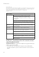
INTRODUCTION Front Panel RJ-45 Ports The EZ Switch 10/100/1000 features 16/24 1000BASE-T ports with RJ-45 connectors located on the front panel of the switch. Because all ports support automatic MDI/MDI-X operation, you can use straight-through cables for all network connections to PCs or servers, or to other switches or hubs. Front Panel LEDs The front panel of the switch provides status LEDs for “at-a-glance” system monitoring. The following table details the functions of the various indicators.
REAR PANEL SMCGS16 SMCGS24 Rear Panel The AC power connector is located on the rear panel of the switch.
INSTALLING THE SWITCH INSTALLING THE SWITCH Before installing the switch, verify that you have all the items listed under “Package Contents.” Note that the switch can be installed on any suitably large flat surface or in a standard EIA 19-inch rack.
INSTRUCTIONS • There should be adequate space (approximately two inches) on all sides for proper air flow. • Make sure twisted-pair cable is always routed away from power lines, fluorescent lighting fixtures and other sources of electrical interference such as radios, transmitters, etc. • Make sure that a properly grounded power outlet is within 2.44 meters (8 feet) of the switch and is powered from an independent circuit breaker.
INSTALLING THE SWITCH Note: If an attached device does not support auto-negotiation, the data rate will be sensed automatically and the communication mode will default to half duplex. 4. Cascading Switches and Other Network Devices: All the ports on the switch support automatic MDI/MDI-X configuration for cable connections. This allows you to use straight-through cable to connect to other switches or hubs from any port on the switch. No crossover cables or other device settings are needed.
INSTRUCTIONS APPLICATION EXAMPLE A typical application for the SMCGS16 is illustrated below.
TROUBLESHOOTING TROUBLESHOOTING Diagnosing Switch Indicators 1. Symptom Power LED does not light after power on. Probable Causes • AC power cord may be defective. Possible Solutions • Check for loose connections. • Check the power outlet by using it for another device. • Replace the AC power cord. 2. Symptom Link LED does not light after connection is made. Probable Causes • Switch port, network card or cable may be defective.
CABLE SPECIFICATIONS CABLES Cable Specifications Cable 10BASE-T 100BASE-TX 1000BASE-T Cable Types and Specifications Type Max. Length 2-pair Cat. 3 or better 100-ohm UTP 100 m (328 ft) 2-pair Cat. 5 or better 100-ohm UTP 100 m (328 ft) 4-pair Cat. 5 or better 100-ohm UTP 100 m (328 ft) Connector RJ-45 RJ-45 RJ-45 10BASE-T/100BASE-TX Pin Assignments Caution: DO NOT plug a phone jack connector into any RJ-45 port. Use only twisted-pair cables with RJ-45 connectors that conform with FCC standards.
CABLES The table below shows the 10BASE-T/100BASE-TX MDI-X and MDI port pinouts. Pin MDI-X Signal Name MDI Signal Name 1 Receive Data plus (RD+) Transmit Data plus (TD+) 2 Receive Data minus (RD-) Transmit Data minus (TD-) 3 Transmit Data plus (TD+) Receive Data plus (RD+) 6 Transmit Data minus (TD-) Receive Data minus (RD-) 4,5,7,8 Not used at 10/100 Mbps Not used at 10/100 Mbps 1000BASE-T Pin Assignments The table below shows the 1000BASE-T MDI and MDI-X port pinouts.
1000BASE-T CABLE REQUIREMENTS 1000BASE-T Cable Requirements All Category 5 UTP cables that are used for 100BASE-TX connections should also work for 1000BASE-T, providing that all four wire pairs are connected. However, it is recommended that for all critical connections, or any new cable installations, 4-pair Category 5e (enhanced Category 5) cable should be used. The Category 5e specifications include test parameters that are only recommendations for Category 5.
PRODUCT SPECIFICATIONS PRODUCT SPECIFICATIONS EZ Switch 10/100/1000 Standards Conformance IEEE 802.
EZ SWITCH 10/100/1000 Weight SMCGS16: 2.0 kg (4.04 lbs) SMCGS24: 2.2 kg (4.85 lbs) MAC Address Table 8 K entries Memory Buffer SMCGS16: 272 Kbits on-chip frame buffer SMCGS24: 400 Kbits on-chip frame buffer Power Consumption SMCGS16: 15.8 Watts SMCGS24: 24.
PRODUCT SPECIFICATIONS 14
FOR TECHNICAL SUPPORT, CALL: From U.S.A. and Canada (24 hours a day, 7 days a week) (800) SMC-4-YOU; Phn: (949) 679-8000; Fax: (949) 679-1481 From Europe :Contact details can be found on www.smc.com INTERNET E-mail address: techsupport@smc.com Driver updates: http://www.smc.com/index.cfm?action=tech_support_drivers_downloads World Wide Web: http://www.smc.com/ For Literature or Advertising Response, Call: U.S.A.