
User's Manual
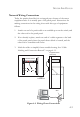
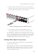
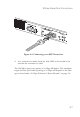
Table Of Contents
- Chapter 1 About the TigerStack II 10/100/1000
- Chapter 2 Network Planning
- Chapter 3 Installing the Switch
- Chapter 4 Making Network Connections
- Appendix A Troubleshooting
- Appendix B Cables
- Appendix C Specifications
- Appendix D German Instructions
- Appendix E Ordering Information
- Glossary
- Index
T
WISTED
-P
AIR
D
EVICES
4-3
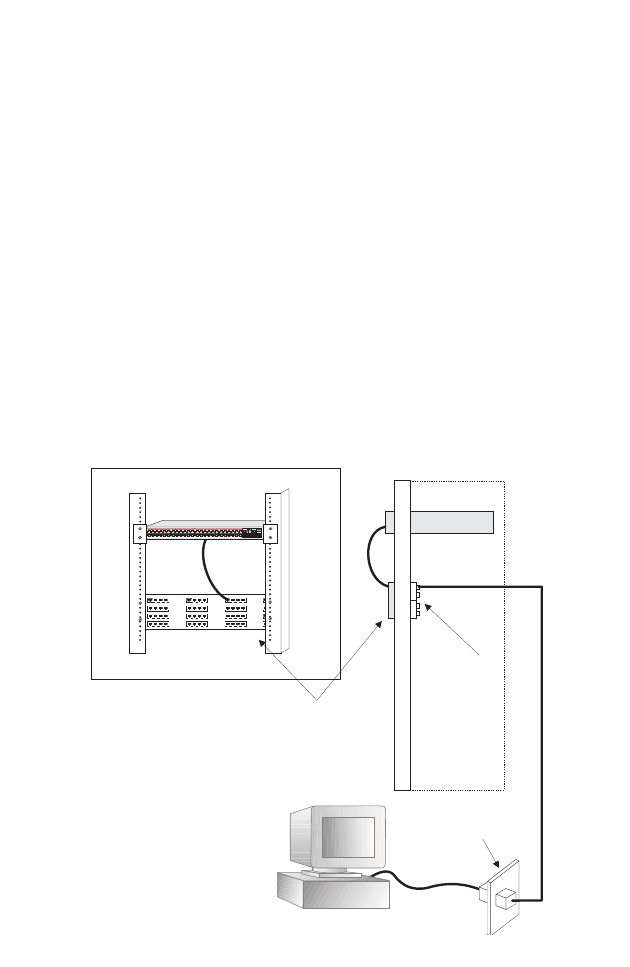
Network Wiring Connections
Today, the punch-down block is an integral part of many of the newer
equipment racks. It is actually part of the patch panel. Instructions for
making connections in the wiring closet with this type of equipment
follows.
1. Attach one end of a patch cable to an available port on the switch, and
the other end to the patch panel.
2. If not already in place, attach one end of a cable segment to the back
of the patch panel where the punch-down block is located, and the
other end to a modular wall outlet.
3. Label the cables to simplify future troubleshooting. See “Cable
Labeling and Connection Records” on page 4-11.
Figure 4-2 Wiring Closet Connections
Equipment Rack
(side view)
Network Switch
Patch Panel
Punch-Down Block
Wall
1
2
3
4
5
6
7
8910
11
12
13
14
15
16
17
18 19 20
21 22
23
24
37
38
39
40
41
42 43 44
45 46
47
48
25
26
27
28
29
30 31 32
33 34
35
36
Master
Select
StackID
45 46
47
48
Console
Pwr
RPS
Diag
StackMaster
TigerStackII
10/100/1000
8848M
Module
StackLink
witch 10/100
6724L3
E
S
4
5
2
4
C