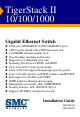
TigerStack II 10/100/1000 Gigabit Ethernet Switch ◆ ◆ ◆ ◆ ◆ ◆ ◆ ◆ ◆ ◆ ◆ ◆ ◆ ◆ 24/48 auto-MDI/MDI-X 10/100/1000BASE-T ports 4 RJ-45 ports shared with 4 SFP transceiver slots 2 10GBASE extender module slots Non-blocking switching architecture Support for a redundant power unit Spanning Tree Protocol, RSTP, and MSTP Up to 32 LACP or static 8-port trunks Layer 2/3/4 CoS support through eight priority queues Layer 3/4 traffic priority with IP Precedence and IP DSCP Full support for VLANs with GVRP IGMP multicas
TigerStack II 10/100/1000 Installation Guide From SMC’s Tiger line of feature-rich workgroup LAN solutions 38 Tesla Irvine, CA 92618 Phone: (949) 679-8000 February 2006 Pub.
Information furnished by SMC Networks, Inc. (SMC) is believed to be accurate and reliable. However, no responsibility is assumed by SMC for its use, nor for any infringements of patents or other rights of third parties which may result from its use. No license is granted by implication or otherwise under any patent or patent rights of SMC. SMC reserves the right to change specifications at any time without notice. Copyright © 2006 by SMC Networks, Inc. 38 Tesla Irvine, CA 92618 All rights reserved.
LIMITED WARRANTY Limited Warranty Statement: SMC Networks, Inc. (“SMC”) warrants its products to be free from defects in workmanship and materials, under normal use and service, for the applicable warranty term. All SMC products carry a standard 90-day limited warranty from the date of purchase from SMC or its Authorized Reseller. SMC may, at its own discretion, repair or replace any product not operating as warranted with a similar or functionally equivalent product, during the applicable warranty term.
WARRANTIES EXCLUSIVE: IF AN SMC PRODUCT DOES NOT OPERATE AS WARRANTED ABOVE, CUSTOMER’S SOLE REMEDY SHALL BE REPAIR OR REPLACEMENT OF THE PRODUCT IN QUESTION, AT SMC’S OPTION. THE FOREGOING WARRANTIES AND REMEDIES ARE EXCLUSIVE AND ARE IN LIEU OF ALL OTHER WARRANTIES OR CONDITIONS, EXPRESS OR IMPLIED, EITHER IN FACT OR BY OPERATION OF LAW, STATUTORY OR OTHERWISE, INCLUDING WARRANTIES OR CONDITIONS OF MERCHANTABILITY AND FITNESS FOR A PARTICULAR PURPOSE.
COMPLIANCES FCC - Class A This equipment has been tested and found to comply with the limits for a Class A digital device, pursuant to part 15 of the FCC Rules. These limits are designed to provide reasonable protection against harmful interference when the equipment is operated in a commercial environment. This equipment generates, uses, and can radiate radio frequency energy and, if not installed and used in accordance with the instruction manual, may cause harmful interference to radio communications.
COMPLIANCES CE Mark Declaration of Conformance for EMI and Safety (EEC) SMC contact for these products in Europe is: SMC Networks Europe, Edificio Conata II, Calle Fructuós Gelabert 6-8, 2o, 4a, 08970 - Sant Joan Despí, Barcelona, Spain.
COMPLIANCES Australia AS/NZS 3548 (1995) - Class A N11846 SMC contact for products in Australia is: SMC Communications Pty. Ltd. Suite 18, 12 Tryon Road, Lindfield NSW2070, Phone: 61-2-94160437 Fax: 61-2-94160474 Safety Compliance Warning: Fiber Optic Port Safety CLASS I LASER DEVICE When using a fiber optic port, never look at the transmit laser while it is powered on. Also, never look directly at the fiber TX port and fiber cable ends when they are powered on.
COMPLIANCES • This unit operates under SELV (Safety Extra Low Voltage) conditions according to IEC 60950. The conditions are only maintained if the equipment to which it is connected also operates under SELV conditions. France and Peru only This unit cannot be powered from IT† supplies. If your supplies are of IT type, this unit must be powered by 230 V (2P+T) via an isolation transformer ratio 1:1, with the secondary connection point labelled Neutral, connected directly to earth (ground).
COMPLIANCES Veuillez lire à fond l'information de la sécurité suivante avant d'installer le Switch: AVERTISSEMENT: L’installation et la dépose de ce groupe doivent être confiés à un personnel qualifié. • Ne branchez pas votre appareil sur une prise secteur (alimentation électrique) lorsqu'il n'y a pas de connexion de mise à la terre (mise à la masse). • Vous devez raccorder ce groupe à une sortie mise à la terre (mise à la masse) afin de respecter les normes internationales de sécurité.
COMPLIANCES Cordon électrique - Il doit être agréé dans le pays d’utilisation Suisse: La prise mâle d’alimentation doit respecter la norme SEV/ASE 1011. Europe La prise secteur doit être conforme aux normes CEE 7/7 (“SCHUKO”) LE cordon secteur doit porter la mention ou et doit être de type HO3VVF3GO.75 (minimum).
COMPLIANCES Warnings and Cautionary Messages Warning: This product does not contain any serviceable user parts. Warning: Installation and removal of the unit must be carried out by qualified personnel only. Warning: When connecting this device to a power outlet, connect the field ground lead on the tri-pole power plug to a valid earth ground line to prevent electrical hazards. Warning: This switch uses lasers to transmit signals over fiber optic cable.
COMPLIANCES End of Product Life Span This product is manufactured in such a way as to allow for the recovery and disposal of all included electrical components once the product has reached the end of its life. Manufacturing Materials There are no hazardous nor ozone-depleting materials in this product. Documentation All printed documentation for this product uses biodegradable paper that originates from sustained and managed forests. The inks used in the printing process are non-toxic.
TABLE OF CONTENTS 1 About the TigerStack II 10/100/1000 . . . . . . . . . . . . . 1-1 Overview . . . . . . . . . . . . . . . . . . . . . . . . . . . . . . . . . . . . . . . . . . . . . . . . . 1-1 Switch Architecture . . . . . . . . . . . . . . . . . . . . . . . . . . . . . . . . . . . 1-2 Network Management Options . . . . . . . . . . . . . . . . . . . . . . . . . . 1-3 Description of Hardware . . . . . . . . . . . . . . . . . . . . . . . . . . . . . . . . . . . . . 1-3 10/100/1000BASE-T Ports . . . . . .
TABLE OF CONTENTS Mounting . . . . . . . . . . . . . . . . . . . . . . . . . . . . . . . . . . . . . . . . . . . . . . . . . 3-4 Rack Mounting . . . . . . . . . . . . . . . . . . . . . . . . . . . . . . . . . . . . . . . 3-4 Desktop or Shelf Mounting . . . . . . . . . . . . . . . . . . . . . . . . . . . . . 3-6 Installing an Optional Module into the Switch . . . . . . . . . . . . . . . . . . . . 3-7 Installing an Optional SFP or XFP Transceiver into the Switch . . . . . . . . . . . . . . . . . . . .
TABLE OF CONTENTS APPENDICES: A Troubleshooting . . . . . . . . . . . . . . . . . . . . . . . . . . . . . .A-1 Diagnosing Switch Indicators . . . . . . . . . . . . . . . . . . . . . . . . . . . . . . . . . A-1 Diagnosing Power Problems with the LEDs . . . . . . . . . . . . . . . A-2 Power and Cooling Problems . . . . . . . . . . . . . . . . . . . . . . . . . . . . . . . . . A-3 Installation . . . . . . . . . . . . . . . . . . . . . . . . . . . . . . . . . . . . . . . . . . . . . . . . A-3 In-Band Access .
TABLE OF CONTENTS Glossary Index xiv
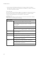
TABLES Table 1-1 Table 1-2 Table 1-3 Table 3-1 Table 3-2 Table 4-1 Table 4-2 Table 4-3 Table 4-4 Table 4-5 Table 4-6 Table 4-7 Table 4-8 Table 4-9 Table A-1 Table A-2 Table B-1 Table B-2 Table E-1 Port Status LEDs . . . . . . . . . . . . . . . . . . . . . . . . . . . . . . . . . . . 1-5 System Status LEDs . . . . . . . . . . . . . . . . . . . . . . . . . . . . . . . . . 1-6 Module LEDs . . . . . . . . . . . . . . . . . . . . . . . . . . . . . . . . . . . . . . 1-9 Optional Transcievers . . . . . . . . . .
FIGURES Figure 1-1 Figure 1-2 Figure 1-3 Figure 1-4 Figure 1-5 Figure 1-6 Figure 2-1 Figure 2-2 Figure 2-3 Figure 2-4 Figure 3-1 Figure 3-2 Figure 3-3 Figure 3-4 Figure 3-5 Figure 3-6 Figure 3-7 Figure 3-8 Figure 3-9 Figure 4-1 Figure 4-2 Figure 4-3 Figure 4-4 Figure B-1 Figure B-2 Figure B-3 Front Panels . . . . . . . . . . . . . . . . . . . . . . . . . . . . . . . . . . . 1-2 Rear Panel . . . . . . . . . . . . . . . . . . . . . . . . . . . . . . . . . . . . . 1-2 Port LEDs . . . . . . . . . . . . . . . .
CHAPTER 1 ABOUT THE TIGERSTACK II 10/100/1000 Overview SMC’s TigerStack II 10/100/1000 SMC8824M and SMC8848M are intelligent multilayer switches (Layer 2, 3) with 24/48 10/100/ 1000BASE-T ports, four of which are combination ports* that are shared with four SFP transceiver slots (see Figure 1-1, Ports 21-24/45-48). The rear panel provides two slots for single-port 10 Gigabit Ethernet hot-swappable expansion modules, and two stacking ports.
ABOUT THE TIGERSTACK II 10/100/1000 These switches can be used to augment or completely replace slow legacy routers, off-loading local IP traffic to release valuable resources for non-IP routing or WAN access. With wire-speed performance, these switches can significantly improve the throughput between IP segments or VLANs.
DESCRIPTION OF HARDWARE These switches include built-in stacking ports that enable up to eight units to be connected together through a 48 Gbps stack backplane. The switch stack can be managed from a master unit using a single IP address. These switches also include two slots on the rear panel for slide-in single-port 10GBASE modules with XFP transceivers. Network Management Options These switches contain a comprehensive array of LEDs for “at-a-glance” monitoring of network and port status.
ABOUT THE TIGERSTACK II 10/100/1000 SFP Slots The Small Form Factor Pluggable (SFP) transceiver slots are shared with four of the RJ-45 ports (ports 21-24 for the SMC8824M and ports 45-48 for the SMC8848M). In its default configuration, if an SFP transceiver (purchased separately) is installed in a slot and has a valid link on its port, the associated RJ-45 port is disabled and cannot be used. The switch can also be configured to force the use of an RJ-45 port or SFP slot, as required.
DESCRIPTION OF HARDWARE Port and System Status LEDs These switches include a display panel for key system and port indications that simplify installation and network troubleshooting. The LEDs, which are located on the front panel for easy viewing, are shown below and described in the following tables.
ABOUT THE TIGERSTACK II 10/100/1000 System Status LEDs 48 Stack Master Pwr RPS Master Select Stack ID 45 Module Diag Stack Link 46 Console 47 TigerStack II 10/100/1000 8848M 48 Figure 1-4 System LEDs Table 1-2 System Status LEDs LED Power Diag RPS 1-6 Condition Status Green Internal power is operating normally. Amber Internal power supply fault. Off Power off. Flashing Green System self-diagnostic test in progress. Green System self-diagnostic test successfully completed.
DESCRIPTION OF HARDWARE Table 1-2 System Status LEDs (Continued) LED Stack Master Stack Link Module Stack ID Condition Status Green Switch is the Master unit of the stack. State may include topology discovery, IP assignment, or normal operations. Flashing Green Switch is the Master unit of the stack, system is initializing. Amber Switch is operating as a Slave unit in the stack. Flashing Amber System in Master arbitration/election state. Off System in standalone mode.
ABOUT THE TIGERSTACK II 10/100/1000 Optional Redundant Power Supply SMC supports an optional Redundant Power Supply (RPS), that can supply power to the switch in the event the internal power supply fails. Power Supply Sockets There are two power sockets on the rear panel of each switch. The standard power socket is for the AC power cord. The socket labeled “RPS” is for the optional Redundant Power Supply (RPS).
FEATURES AND BENEFITS Extender Module LEDs The optional 10GBASE slide-in module includes its own integrated LED indicators on the module’s front panel. The following table describes the LEDs. Table 1-3 Module LEDs LED Condition Link/ On/Flashing Activity Green Off Status Port has a valid link at 10 Gbps. Flashing indicates activity. There is no link on the port.
ABOUT THE TIGERSTACK II 10/100/1000 • Provides stacking capability via high-speed serial ports with 48 Gbps stacking bandwidth. Up to 8 units can be stacked together. Expandability • Supports 1000BASE-SX, 1000BASE-LX and 1000BASE-ZX SFP transceivers. • Optional 10G single-port expansion module with an XFP transceiver slot. Performance • Transparent bridging. • Aggregate duplex bandwidth of up to 128 Gbps for the SMC8824M or 176 Gbps for the SMC8848M.
CHAPTER 2 NETWORK PLANNING Introduction to Switching A network switch allows simultaneous transmission of multiple packets via non-crossbar switching. This means that it can partition a network more efficiently than bridges or routers. These switches have, therefore, been recognized as one of the most important building blocks for today’s networking technology.
NETWORK PLANNING Application Examples The TigerStack II 10/100/1000 is not only designed to segment your network, but also to provide a wide range of options in setting up network connections and linking VLANs or IP subnets. Some typical applications are described below. Collapsed Backbone The TigerStack II 10/100/1000 is an excellent choice for mixed Ethernet, Fast Ethernet, and Gigabit Ethernet installations where significant growth is expected in the near future.
APPLICATION EXAMPLES Network Aggregation Plan With 24 or 48 parallel bridging ports (i.e., 24 or 48 distinct collision domains), a Gigabit switch stack can collapse a complex network down into a single efficient bridged node, increasing overall bandwidth and throughput. In the figure below, the 10/100/1000BASE-T ports in a stack of 48-port Gigabit Ethernet switches are providing 1000 Mbps connectivity through stackable switches. In addition, the switches are also connecting several servers at 10 Gbps.
NETWORK PLANNING Remote Connections with Fiber Cable Fiber optic technology allows for longer cabling than any other media type. A 1000BASE-SX (MMF) link can connect to a site up to 550 meters away, a 1000BASE-LX (SMF) link up to 5 km, and a 1000BASE-ZX link up to 100 km. This allows a switch stack to serve as a collapsed backbone, providing direct connectivity for a widespread LAN.
APPLICATION EXAMPLES Making VLAN Connections These switches support VLANs which can be used to organize any group of network nodes into separate broadcast domains. VLANs confine broadcast traffic to the originating group, and can eliminate broadcast storms in large networks. This provides a more secure and cleaner network environment. VLANs can be based on untagged port groups, or traffic can be explicitly tagged to identify the VLAN group to which it belongs.
NETWORK PLANNING Application Notes 1. Full-duplex operation only applies to point-to-point access (such as when a switch is attached to a workstation, server or another switch). When the switch is connected to a hub, both devices must operate in half-duplex mode. 2. For network applications that require routing between dissimilar network types, you can attach these switches directly to a multiprotocol router. 3.
CHAPTER 3 INSTALLING THE SWITCH Selecting a Site TigerStack II 10/100/1000 units can be mounted in a standard 19-inch equipment rack or on a flat surface. Be sure to follow the guidelines below when choosing a location. • The site should: - be at the center of all the devices you want to link and near a power outlet.
INSTALLING THE SWITCH Ethernet Cabling To ensure proper operation when installing the switches into a network, make sure that the current cables are suitable for 10BASE-T, 100BASE-TX or 1000BASE-T operation. Check the following criteria against the current installation of your network: • Cable type: Unshielded twisted pair (UTP) or shielded twisted pair (STP) cables with RJ-45 connectors; Category 3 or better for 10BASE-T, Category 5 or better for 100BASE-TX, and Category 5, 5e or 6 for 1000BASE-T.
EQUIPMENT CHECKLIST Equipment Checklist After unpacking the TigerStack II 10/100/1000 unit, check the contents to be sure you have received all the components. Then, before beginning the installation, be sure you have all other necessary installation equipment.
INSTALLING THE SWITCH Mounting A TigerStack II 10/100/1000 unit can be mounted in a standard 19-inch equipment rack or on a desktop or shelf. Mounting instructions for each type of site follow.
MOUNTING To rack-mount devices: 1. Attach the brackets to the device using the screws provided in the Bracket Mounting Kit. Stack Ma ster Pwr Maste Selec r t Stack ID RPS Modu le Stack Diag Link Cons Tig 10 erSta /1 8848 00/1 ck II 00 M 0 ole 45 46 47 48 Figure 3-2 Attaching the Brackets 2. Mount the device in the rack, using four rack-mounting screws (not provided).
INSTALLING THE SWITCH 3. If installing a single switch only, turn to “Connecting to a Power Source” at the end of this chapter. 4. If installing multiple switches, mount them in the rack, one below the other, in any order. 5. If also installing an RPS, mount it in the rack below the other devices. Desktop or Shelf Mounting 1. Attach the four adhesive feet to the bottom of the first switch.
INSTALLING AN OPTIONAL MODULE INTO THE SWITCH Installing an Optional Module into the Switch M1 Figure 3-5 Installing an Optional Module Note: The slide-in modules are hot-swappable, you do not need to power off the switch before installing or removing a module. To install an optional module into the switch, do the following: 1. Remove the blank metal plate (or a previously installed module) from the appropriate slot by removing the two screws with a flat-head screwdriver. 2.
INSTALLING THE SWITCH 6. The Module LED on the switch’s front panel should turn green to confirm that the module is correctly installed and ready to use.
CONNECTING SWITCHES IN A STACK 3. Slide the transceiver into the slot until it clicks into place. Note: SFP and XFP transceivers are hot-swappable. The switch does not need to be powered off before installing or removing a transceiver. However, always first disconnect the network cable before removing a transceiver. Note: SFP and XFP transceivers are not provided in the switch package. Connecting Switches in a Stack Figure 3-7 shows how the stack cables are connected between switches in a stack.
INSTALLING THE SWITCH 4. (Optional) To form a wrap-around topology, plug one end of a stack cable into the Down port on the bottom unit and the other end into the Up port on the top unit. Figure 3-7 Making Stacking Connections 5. Select the Master unit in the stack by pressing the Master button in on only one of the switches. Only one switch in the stack can operate as the Master, all other units operate in slave mode.
CONNECTING SWITCHES IN A STACK Stacking Topologies All units in the stack must be connected via stacking cable. You can connect units in a simple cascade configuration, connecting Down ports to Up ports, from the top unit to the bottom unit. Using this “line” topology, if any link or unit in the stack fails, the stack is split and two separate segments are formed. The Stack Link LEDs on the units that are disconnected flash to indicate that the stack link between them is not functioning.
INSTALLING THE SWITCH Connecting to a Power Source To connect a device to a power source: 1. Insert the power cable plug directly into the socket located at the back of the device. Figure 3-8 Power Socket 2. Plug the other end of the cable into a grounded, 3-pin, AC power source. Note: For international use, you may need to change the AC line cord. You must use a line cord set that has been approved for the socket type in your country. 3.
CONNECTING TO THE CONSOLE PORT Connecting to the Console Port The RJ-45 serial port on the switch’s front panel is used to connect to the switch for out-of-band console configuration. The on-board configuration program can be accessed from a terminal or a PC running a terminal emulation program. The pin assignments used to connect to the serial port are provided in the following table.
INSTALLING THE SWITCH 3-14
CHAPTER 4 MAKING NETWORK CONNECTIONS Connecting Network Devices The TigerStack II 10/100/1000 units are designed to interconnect multiple segments (or collision domains). It can be connected to network cards in PCs and servers, as well as to hubs, switches or routers. It may also be connected to devices using optional XFP or SFP transceivers. Twisted-Pair Devices Each device requires an unshielded twisted-pair (UTP) cable with RJ-45 connectors at both ends.
MAKING NETWORK CONNECTIONS Connecting to PCs, Servers, Hubs and Switches 1. Attach one end of a twisted-pair cable segment to the device’s RJ-45 connector. Figure 4-1 Making Twisted-Pair Connections 2. If the device is a PC card and the switch is in the wiring closet, attach the other end of the cable segment to a modular wall outlet that is connected to the wiring closet. (See “Network Wiring Connections” on page 4-3.) Otherwise, attach the other end to an available port on the switch.
TWISTED-PAIR DEVICES Network Wiring Connections Today, the punch-down block is an integral part of many of the newer equipment racks. It is actually part of the patch panel. Instructions for making connections in the wiring closet with this type of equipment follows. 1. Attach one end of a patch cable to an available port on the switch, and the other end to the patch panel. 2.
MAKING NETWORK CONNECTIONS Fiber Optic SFP Devices An optional Gigabit SFP transceiver (1000BASE-SX, 1000BASE-LX or 1000BASE-ZX) can be used for a backbone connection between switches, or for connecting to a high-speed server. Each single-mode fiber port requires 9/125 micron single-mode fiber optic cable with an LC connector at both ends. Each multimode fiber optic port requires 50/125 or 62.5/125 micron multimode fiber optic cabling with an LC connector at both ends.
10 GBPS FIBER OPTIC CONNECTIONS 3. Connect one end of the cable to the LC port on the switch and the other end to the LC port on the other device. Since LC connectors are keyed, the cable can be attached in only one orientation. 39 40 41 42 43 44 45 46 47 48 Stac k Ma ste r Pwr Maste Selec r t Stac k ID RPS Modu le Stac Diag k Lin k Cons ole Tig 10 erSta /1 8848 00/1 ck II 00 M 0 45 46 47 48 Figure 4-3 Making Connections to SFP Transceivers 4.
MAKING NETWORK CONNECTIONS Warning: These switches use lasers to transmit signals over fiber optic cable. The lasers are compliant with the requirements of a Class 1 Laser Product and are inherently eye safe in normal operation. However, you should never look directly at a transmit port when it is powered on. Note: When selecting a fiber device, considering safety, please make sure that it can function at a temperature that is not less than the recommended maximum operational temperature of the product.
10 GBPS FIBER OPTIC CONNECTIONS M1 Figure 4-4 Connecting to an XFP Transceiver 4. As a connection is made, check the Link LED on the module to be sure that the connection is valid. The 10G fiber optic ports operate at 10 Gbps full duplex. The maximum length for fiber optic cable operating at 10 Gbps will depend on the fiber type as listed under “10 Gbps Ethernet Collision Domain” on page 4-8.
MAKING NETWORK CONNECTIONS Connectivity Rules When adding hubs (repeaters) to your network, please follow the connectivity rules listed in the manuals for these products. However, note that because switches break up the path for connected devices into separate collision domains, you should not include the switch or connected cabling in your calculations for cascade length involving other devices.
CONNECTIVITY RULES Table 4-2 Maximum 10GBASE-LR 10 Gigabit Ethernet Cable Length Fiber Size Fiber Bandwidth Maximum Cable Length Connector 9/125 micron single-mode fiber N/A 10 km (6.2 miles) LC Table 4-3 Maximum 10GBASE-ER 10 Gigabit Ethernet Cable Length Fiber Size Fiber Bandwidth Maximum Cable Length Connector 9/125 micron single-mode fiber N/A 40 km (24.
MAKING NETWORK CONNECTIONS Table 4-7 Maximum 1000BASE-ZX Fiber Optic Cable Length Fiber Diameter Fiber Bandwidth Cable Length Range Connector 9/125 micron single-mode fiber N/A 70* - 100 km (43.5 - 62.
CABLE LABELING AND CONNECTION RECORDS Cable Labeling and Connection Records When planning a network installation, it is essential to label the opposing ends of cables and to record where each cable is connected. Doing so will enable you to easily locate inter-connected devices, isolate faults and change your topology without need for unnecessary time consumption. To best manage the physical implementations of your network, follow these guidelines: • Clearly label the opposing ends of each cable.
MAKING NETWORK CONNECTIONS 4-12
APPENDIX A TROUBLESHOOTING Diagnosing Switch Indicators Table A-1 Troubleshooting Chart Symptom Action Power LED is Off • Check connections between the switch, the power cord, and the wall outlet. • Contact your dealer for assistance. • Contact SMC Technical Support. Power LED is Amber • Internal power supply has failed. Contact your local dealer for assistance. Diag LED is Amber • Power cycle the switch to try and clear the condition.
TROUBLESHOOTING Table A-1 Troubleshooting Chart (Continued) Symptom Action Stack Link LED is Flashing Green/Amber • The uplink/downlink has failed. • For the indicated stack link, check that the stacking cables are properly connected. Replace the stacking cable if necessary. • Power cycle the switch to try and clear the condition. • Verify that the switch and attached device are powered on. • Be sure the cable is plugged into both the switch and corresponding device.
POWER AND COOLING PROBLEMS Power and Cooling Problems If the power indicator does not turn on when the power cord is plugged in, you may have a problem with the power outlet, power cord, or internal power supply. However, if the unit powers off after running for a while, check for loose power connections, power losses or surges at the power outlet, and verify that the fans on the unit are unobstructed and running prior to shutdown.
TROUBLESHOOTING Stack Troubleshooting If a stack fails to initialize or function, first check the following items: • Check that all stacking cables are properly connected. • Check if any stacking cables appear damaged. • Check that only one Stack Master button is pressed in. • Check that all switches in the stack are powered on. After checking all items, reboot all the switches in the stack. Switches in the stack may be configured using a ring- or line-topology.
APPENDIX B CABLES Twisted-Pair Cable and Pin Assignments For 10BASE-T/100BASE-TX connections, a twisted-pair cable must have two pairs of wires. For 1000BASE-T connections the twisted-pair cable must have four pairs of wires. Each wire pair is identified by two different colors. For example, one wire might be green and the other, green with white stripes. Also, an RJ-45 connector must be attached to both ends of the cable.
CABLES 10BASE-T/100BASE-TX Pin Assignments Use unshielded twisted-pair (UTP) or shielded twisted-pair (STP) cable for RJ-45 connections: 100-ohm Category 3 or better cable for 10 Mbps connections, or 100-ohm Category 5 or better cable for 100 Mbps connections. Also be sure that the length of any twisted-pair connection does not exceed 100 meters (328 feet).
TWISTED-PAIR CABLE AND PIN ASSIGNMENTS Straight-Through Wiring If the twisted-pair cable is to join two ports and only one of the ports has an internal crossover (MDI-X), the two pairs of wires must be straight-through. (When auto-negotiation is enabled for any RJ-45 port on these switches, you can use either straight-through or crossover cable to connect to any device type.) You must connect all four wire pairs as shown in the following diagram to support Gigabit Ethernet connections.
CABLES Crossover Wiring If the twisted-pair cable is to join two ports and either both ports are labeled with an “X” (indicating MDI-X) or neither port is labeled with an “X” (which indicates MDI), a crossover must be implemented in the wiring. (When auto-negotiation is enabled for any RJ-45 port on these switches, you can use either straight-through or crossover cable to connect to any device type.
TWISTED-PAIR CABLE AND PIN ASSIGNMENTS 1000BASE-T Pin Assignments All 1000BASE-T ports support automatic MDI/MDI-X operation, so you can use straight-through cables for all network connections to PCs or servers, or to other switches or hubs. The table below shows the 1000BASE-T MDI and MDI-X port pinouts. These ports require that all four pairs of wires be connected. Note that for 1000BASE-T operation, all four pairs of wires are used for both transmit and receive.
CABLES Note that when testing your cable installation, be sure to include all patch cables between switches and end devices. Adjusting Existing Category 5 Cabling to Run 1000BASE-T If your existing Category 5 installation does not meet one of the test parameters for 1000BASE-T, there are basically three measures that can be applied to try and correct the problem: 1. Replace any Category 5 patch cables with high-performance Category 5e or Category 6 cables. 2.
APPENDIX C SPECIFICATIONS Physical Characteristics Ports SMC8824M 20 10/100/1000BASE-T, with auto-negotiation 4 10/100/1000BASE-T shared with 4 SFP transceiver slots.
SPECIFICATIONS Switching Database 8K MAC address entries, 1K static MAC addresses; 2K IP or 1K IPv6 entries in host table, 1K ARP entries, 512 IP or 256 IPv6 entries in routing table, 64 static IP routes, 256 IP interfaces; 32 multicast groups LEDs System: Stack Master, Stack Link, Module, Power, Diag (Diagnostics), RPS (Redundant Power Supply) Port: Status (link, speed, activity) Weight SMC8824M: 3.72 kg (8.44 lbs) SMC8848M: 4.34 kg (9.59 lbs) Size 44.0 x 41.5 x 4.4 cm (17.3 x 16.3 x 1.7 in.
SWITCH FEATURES Maximum Current SMC8824M: 0.59 A @ 110 VAC (without expansion modules) 0.72 A @ 110 VAC (with two expansion modules) 0.36 A @ 240 VAC (without expansion modules) 0.37 A @ 240 VAC (with two expansion modules) SMC8848M: 0.97 A @ 110 VAC (without expansion modules) 1.16 A @ 110 VAC (with two expansion modules) 0.47 A @ 240 VAC (without expansion modules) 0.
SPECIFICATIONS Standards IEEE 802.3-2002 Ethernet, Fast Ethernet, Gigabit Ethernet IEEE 802.3ae 10 Gigabit Ethernet IEEE 802.1D Spanning Tree Protocol IEEE 802.1w Rapid Spanning Tree Protocol IEEE 802.1s Multiple Spanning Tree Protocol IEEE D802.1Q Virtual LAN ISO/IEC 8802-3 Compliances CE Mark Emissions FCC Class A Industry Canada Class A EN55022 (CISPR 22) Class A EN 61000-3-2/3 VCCI Class A C-Tick - AS/NZS 3548 (1995) Class A Immunity EN 61000-4-2/3/4/5/6/8/11 Safety CSA/CUS (CSA 22.2.
EXTENDER MODULES Extender Modules 10G Extender Module (XFP) Ports 1 slot for 10GBASE XFP transceiver Communication Speed 10 Gbps Communication Mode Full duplex Network Interface XFP slot Standards IEEE 802.
SPECIFICATIONS C-6
APPENDIX D GERMAN INSTRUCTIONS Eine Site Auswählen (Selecting a Site - German) Die Schalter können in ein Standard-19-Zoll-Ausrüstungsgestell oder auf eine flache Ebene montiert werden. Zum Auswählen eines Standortes beachten Sie bitte die nachstehenden Richtlinien.
MONTAGE (RACK MOUNTING INSTRUCTIONS - GERMAN) moglichen elektrischen Storungen verlegt wird, wie z. B. von Radios und Transmittern. • Sicherstellen, dass das Gerat an eine separate Stromquelle mit Erdanschlus mit einer Netzspannung von 100 bis 240 V AC (Wechselstromspannung), 50 bis 60 Hz, und innerhalb in einem Abstand von 2,44 m (8 Fus) zu jedem Gerat installiert wird und on einem separaten Trennschalter bzw. Leistungsschalter mit Strom versorgt wird.
GERMAN INSTRUCTIONS So montieren Sie Geräte an ein Rack: 1. Befestigen Sie die Metallwinkel mit den im Metallwinkel-Montageset erhältlichen Schrauben an dem Gerät. 2. Befestigen Sie das Gerät mit vier Rackmontageschrauben (nicht beigelegt) an dem Rack. 3. Wenn Sie nur einen Switch installieren, dann springen Sie bitte über zu "Verbinden mit einer Stromquelle" auf Seite 3-12 am Ende dieses Kapitels. 4.
MONTAGE (RACK MOUNTING INSTRUCTIONS - GERMAN) D-4
APPENDIX E ORDERING INFORMATION Table E-1 TigerStack II 10/100/1000 Products and Accessories Product Number Description SMC8848M 48-port 10/100/1000 stackable managed switch with optional 10 Gigabit uplink SMC8824M 24-port 10/100/1000 stackable managed switch with optional 10 Gigabit uplink SMCBGSLCX1 1-port 1000BASE-SX Small Form Pluggable (SFP) mini-GBIC transceiver SMCBGLLCX1 1-port 1000BASE-LX Small Form Pluggable (SFP) mini-GBIC transceiver SMCBGZLCX1 1-port 1000BASE-ZX Small Form Pluggable
ORDERING INFORMATION E-2
GLOSSARY 10BASE-T IEEE 802.3 specification for 10 Mbps Ethernet over two pairs of Category 3 or better UTP cable. 100BASE-TX IEEE 802.3u specification for 100 Mbps Fast Ethernet over two pairs of Category 5 or better UTP cable. 1000BASE-LX IEEE 802.3z specification for Gigabit Ethernet over two strands of 50/125, 62.5/125 or 9/125 micron core fiber cable. 1000BASE-SX IEEE 802.3z specification for Gigabit Ethernet over two strands of 50/125 or 62.5/125 micron core fiber cable. 1000BASE-T IEEE 802.
GLOSSARY 10GBASE-LR IEEE 802.3ae specification for 10 Gigabit Ethernet over two strands of 9/125 micron core single-mode fiber cable. 10GBASE-SR IEEE 802.3ae specification for 10 Gigabit Ethernet over two strands of 50/125 micron core multimode fiber cable. 10 Gigabit Ethernet A 10 Gbps network communication system based on Ethernet. Auto-Negotiation Signalling method allowing each node to select its optimum operational mode (e.g.
GLOSSARY End Station A workstation, server, or other device that does not forward traffic. Ethernet A network communication system developed and standardized by DEC, Intel, and Xerox, using baseband transmission, CSMA/CD access, logical bus topology, and coaxial cable. The successor IEEE 802.3 standard provides for integration into the OSI model and extends the physical layer and media with repeaters and implementations that operate on fiber, thin coax and twisted-pair cable.
GLOSSARY IEEE 802.3ae Defines the physical layer specifications for 10 Gigabit Ethernet. IEEE 802.3u Defines CSMA/CD access method and physical layer specifications for 100BASE-TX Fast Ethernet. (Now incorporated in IEEE 802.3-2002.) IEEE 802.3x Defines Ethernet frame start and stop requests and timers used for flow control on full-duplex links. (Now incorporated in IEEE 802.3-2002.) IEEE 802.3z Defines CSMA/CD access method and physical layer specifications for 1000BASE Gigabit Ethernet.
GLOSSARY Management Information Base (MIB) An acronym for Management Information Base. It is a set of database objects that contains information about the device. Media Access Control (MAC) A portion of the networking protocol that governs access to the transmission medium, facilitating the exchange of data between network nodes. Modal Bandwidth Bandwidth for multimode fiber is referred to as modal bandwidth because it varies with the modal field (or core diameter) of the fiber.
GLOSSARY Transmission Control Protocol/Internet Protocol (TCP/IP) Protocol suite that includes TCP as the primary transport protocol, and IP as the network layer protocol. UTP Unshielded twisted-pair cable. Virtual LAN (VLAN) A Virtual LAN is a collection of network nodes that share the same collision domain regardless of their physical location or connection point in the network.
INDEX Numerics C 10 Gbps connectivity rules 4-8 10 Mbps connectivity rules 4-10 100 Mbps connectivity rules 4-10 1000 Mbps connectivity rules 4-9 1000BASE-LX fiber cable lengths 4-9 1000BASE-SX fiber cable lengths 4-9 1000BASE-T pin assignments B-5 ports 1-3 1000BASE-ZX fiber cable lengths 4-10 100BASE-TX cable lengths 4-10 ports 1-3 10BASE-T ports 1-3 10BASE-T/100BASE-TX pin assignments B-2 10G modules 1-8 10GBASE-ER fiber cable length 4-9 10GBASE-LR fiber cable length 4-9 10GBASE-SR fiber cable length 4
INDEX G M grounding for racks 3-4 management agent 1-3 features 1-10, C-3, C-4 out-of-band 1-3 SNMP 1-3 web-based 1-3 modules, 10G 1-8 modules, 10GBASE-LR C-5 mounting the switch in a rack 3-4 on a desktop or shelf 3-6 I IEEE 802.3 Ethernet 1-9 IEEE 802.3ae 10 Gigabit Ethernet 1-9 IEEE 802.3u Fast Ethernet 1-9 IEEE 802.
INDEX R rack mounting 3-4 redundant power unit 1-8 RJ-45 port 1-3 connections 4-1 pinouts B-5 RPU connecting 3-12 installing in a rack 3-6 installing on a desktop 3-6 RPU, optional redundant power unit 1-8 rubber foot pads, attaching 3-6 S screws for rack mounting 3-3 site selelction 3-1 SNMP agent 1-3 specifications compliances C-3, C-4 environmental C-2 extender modules C-5 physical C-1 power C-2 standards compliance C-4 IEEE C-4 status LEDs 1-5 surge suppressor, using 3-1 switch architecture 1-2 switc
INDEX Index-4
FOR TECHNICAL SUPPORT, CALL: From U.S.A. and Canada (24 hours a day, 7 days a week) (800) SMC-4-YOU; (949) 679-8000; Fax: (949) 679-1481 From Europe: Contact details can be found on www.smc-europe.com or www.smc.com INTERNET E-mail addresses: techsupport@smc.com european.techsupport@smc-europe.com Driver updates: http://www.smc.com/index.cfm?action=tech_support_drivers_downloads World Wide Web: http://www.smc.com http://www.smc-europe.com FOR LITERATURE OR ADVERTISING RESPONSE, CALL: U.S.A.