USER MANUAL SPACEPC® 1232 SERIES PC/104 SINGLE BOARD COMPUTER (ALSO KNOWN AS THE CPU-1232) 5/18/2005 MNL-0501F-01
ABOUT THIS MANUAL This manual is meant for engineers and programmers who wish to use the Parvus SpacePC® 1232. It contains technical specifications, and describes the connectors and how to properly use and configure the product.
Table of Contents Table of Contents .......................................................................................................................... 3 Chapter 1 Product Overview .................................................................................................... 6 SpacePC 1232 Functional Block Diagram................................................................................... 7 Product Definition.............................................................................
J19 LCD-TFT Section ................................................................................................................ 36 Chapter 4 The Setup Program................................................................................................ 39 How to use the Setup program .................................................................................................. 40 The Setup pages.....................................................................................................
A.3 Safety Summary.............................................................................................................. 81 Ground the Instrument ........................................................................................................ 81 Do Not Substitute Parts or Modify Equipment..................................................................... 82 Flammability .....................................................................................................................
Chapter 1 Product Overview The SpacePC 1232 is a highly integrated PC/104 CPU module, based on the AMD / National Semiconductor Geode GX1 MMX Enhanced microprocessor. It is also known as the CPU-1232. Related Products: Development kit for SpacePC 1232 / multifunction adapter Cable set for SpacePC 1232 AC97-CODEC and USB adapter Parallel to Floppy adapter Ethernet RJ45 adapter For a complete list of our products please go to our web site: www.parvus.
SpacePC 1232 Functional Block Diagram The figure below shows the functional blocks diagram of the module. CPU-1232 CPU-1232 Module Figure 1. Functional block diagram of the Ethernet 10/100 SDRAM 2 x USB Fast Ethernet Controller Speakers Line-out USB + AC97 Codec Adapter CD-ROM Audio NS Geode Gx1 Processor LCD-TFT NS Geode CS5530A I/O Companion Microphone SpacePC 1232 3.
Product Definition SpacePC 1232 PC/104 CPU Module ¾ PC/AT compatible. ¾ PC/104 Form Factor: 3.550” x 3.775” (90 X 96 mm); height: 15 mm (0.6”) ¾ Low power consumption. ¾ High reliability. ¾ Operating systems supported: DOS (from 3.0 to 6.22), QNX, VxWorks, PSOS, Windows 3.11, Windows 95, Windows 98, Windows NT, Windows 2000, Linux. AMD / NS Geode GX1 MMX Enhanced microprocessor ¾ 266MHz clock speed (300MHz version only available with a minimum quantity purchase) ¾ 1.
¾ Two cascaded 8259 interrupt controllers (15 interrupt channels) ¾ Three 8254 counter/timers (There are no extra timers) ¾ Three extra timers Peripherals ¾ Two serial ports UART 16550A-compatible: one selectable between RS232/422/485 and one RS232 only ¾ One bidirectional parallel port: selectable between EPP, ECP, SPP ¾ One USB port compliant with the Open Host Controller Interface (OHCI) ¾ One AC97 port (CODEC board needed) ¾ One floppy disk interface available on the parallel port (J5)
¾ Display resolutions up to 1280x1024 8-bit per pixel ¾ UMA (Unified Memory Architecture) LCD-TFT interface ¾ Also LCD-TFT flat panels can be connected to the SpacePC 1232 If LCD-TFT and CRT screens are used at the same time, the refresh frequency of the CRT video will be modified according to the LCD-TFT setting. It may be possible to view flickering on the CRT screen.
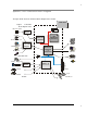
Chapter 2 Jumper Description This chapter shows the jumpers layout and explains how to setup the jumpers. Jumper Layout and Configuration Figure below, shows the jumper layout of the SpacePC 1232 module. In the below figure, the jumpers are indicated as JP followed by the jumper's number, while pin 1 of every jumper is indicated by a red square pad. Figure 2.
The following jumpers are located on the module: One 3-pin jumper (JP5) for which there are only two possibilities: ¾ Connecting pin 1 to pin 2 (which will be indicated as 1-2) ¾ Connecting pin 2 to pin 3 (which will be indicated as 2-3) Three 2-pin jumpers (JP1, JP7, JP8), which can be set as follows: ¾ Pin 1 connected to pin 2 (which will be indicated as ‘Closed’) ¾ Pin 1 and pin 2 not connected (which will be indicated as ‘Open’) The following table provides a quick cross-reference for the SpaceP
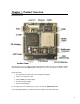
Chapter 3 Connectors Description This chapter provides a brief description of the SpacePC 1232 module’s connectors, with their positions and functions. Connectors Layout In the following figure are shown the connectors with their layout and function/s. AC97 Audio 2x USB J10 VGA JP10 IDE Led J11 Auxiliary Power NS Geode CS5530A I/O Companion J14 PS/2 Mouse J19 SSD J18 Ethernet J1 J2 NS Geode Gx1 Processor U1 J16 J6 Serial 2 J13 J17 J3 Multifunction Connector Figure 3.
Table below lists the name of the connectors with their function and the reference page. Table 2.
J1 and J2 for the ISA Bus The ISA BUS Connectors J1 and J2 carry the signals for the ISA Bus. These signals match definitions of the IEEE P996 standard. Below is shown a picture of the ISA BUS Figure 4. ISA BUS layout According to PC/104 specifications, KEYs are filled holes in the upper side and missing pins in the lower side of the bus connector. This is made to avoid the wrong insertion in/of another module.
8. Press evenly the module onto the PC/104 stack. The picture below shows a typical module stack with 2 PC/104 modules, 1 PC/104 16-BIT module, and 1 PC/104 8-BIT module. The maximum configuration for the PCI bus of PC/104 modules is 4 plus the Host Board. If standard PC/104 modules are used in the stack, they must be the top module(s) because they will normally not include the PCI bus. Stackthrough 8-bit module 0.435 in. (11 mm) 0.6 in. (15mm) Spacers (4 plcs.) 0.6 in.
J3 for Multifunction & J14 for Mouse J3 is a double row 5 x 2 pin with 2.54-mm step connector and allows the connection of a speaker, a keyboard, and a battery to the SpacePC 1232 module. J14 is a 4 pin with 2-mm step connector and allows the connection of a PS/2 compatible mouse. Later on there is a brief description about the Parvus Multifunction Adapter and the VGA and the Ethernet. J3 Multifunction Connector J3 Multifunction Connector Figure 6.
Below is shown the connector pinout: Table 3. Pin 1 2 3 4 5 6 7 8 9 10 Multifunction connector Signal Function SPKRSpeaker output SPKR+ Speaker output (+5V) RESET External reset WDTL Watch dog timeout latch KBD Keyboard data KBC Keyboard clock GND Ground signal KBP Keyboard power (+5V) BAT External Battery input P_B External Power Button This section of the connector implements the following functions: Keyboard An AT compatible keyboard can be connected to the module through connector J3.
The audio output is based on two signals: one come from the output of Timer 2, and the other come from I/O port 61h compliant with the AT Standard. Power button If the soft power management is enabled, a low signal in the pin10 turns the system on or off. J14 Mouse Connector A PS/2 compatible mouse can be connected to the J14 connector (4pins, 2-mm step). J14 PS/2 Mouse Figure 7. J14 Connector layout The J14 pin out is given below. Table 5.
Parvus Multifunction Adapter Parvus Multifunction Adapter simplifies the connection of mouse and keyboard with two PS/2 connectors, providing also a speaker, a battery and a reset pushbutton. Battery Speaker J1 J6 J5 J4 To J14 Conn. of CPU Board (Mouse sign.) Not used To Multif. Conn. of CPU Board Power Led J3 J2 S1 Mouse Keyboard Reset Pushbutton Figure 8.
Table 6. PIN # 1 2-8 3 4-10 5 6 7 9 Table 7. PIN # 1 2 3 4 J4 To CPU Multifunction Connector SIGNAL SPKR +5V RES_PB_IN N.C.
J4 for PARALLEL or FDD A parallel port is available on connector J4 of the SpacePC 1232 module. This connector is a 13x2 pin with 2.54-mm step. Connector J4 has two operating modes: Parallel port mode Floppy disk interface mode The selection between the two modes can be performed in the BIOS Setup (see Chapter 4). J4 Parallel Port Figure 9. J4 Connector Layout The following table gives the pin-out of connector J4 for both functions (parallel port and floppy). Table 8.
14 15 16 17 GND PD6 GND PD7 18 19 GND ACK# (*) 20 21 22 23 GND BSY GND PE Signal ground Printer Data 6 Signal ground MSB Printer Data Signal ground Character accepted Signal ground Busy Signal ground Paper End -out -out 20 8 21 9 GND MTR0# (*) GND MEDIA-ID1# (*) Signal ground Motor On 0 In/out Signal ground -In 14 15 16 17 -in 22 10 GND DS1# Signal ground -Drive Select 1 Out 18 19 -in -in 23 11 24 12 GND MTR1# (*) GND WDATA# (*) -Out -Out 20 21 22 23 25 13 GND WGATE# (*) Signal g
To the FDD Cable/Connector Female Config. Male Config. Power Supply GND PIN1 +5V PIN2 To the Parallel Port Figure 10. Parvus Floppy Disk Drive Adapter WARNING! TO AVOID MALFUNCTIONS, BE CAREFUL TO CONNECT THE FLOPPY DRIVE CABLE IN THE FOLLOWING WAY: The most diffuse Floppy Drive flat cable that is possible to find on the market is structured as shown in the following schematic picture. With this type of cable only the second connector can be connected to the Parvus Floppy Disk Drive Adapter.
J5 Serial 1 J6 Serial 2 Figure 12. J5 and J6 Connectors layout Both can be set as RS232 but only one (J5) can be set as RS422-485. Refer to the following tables for the serial ports pinout assignment in RS232/422/485 modes. Table 9. J5, J6 Serial Port Connectors in RS232 mode Pin 1 2 3 4 5 6 7 Signal DCD DSR RX RTS TX CTS DTR 8 9,10 RI GND Table 10.
- bit 0 of the MCR register = 0 means RS485 line receiving - bit 0 of the MCR register = 1 means RS485 line transmitting The I/O address of the MCR is "Serial port Base address"+4H. See Chapter 4 for info about the Serial ports configuration. J7 for 2 x USB, J8 for AUDIO-CODEC J7 for 2 x USB J7 is a double row 4 x 2 pin with 2.00-mm step connector. 2 x USB Figure 13. J7 Connector layout Two USB ports are provided on the SpacePC 1232 module for the connection of USB devices. Table 11.
Note. USB devices shouldn’t be directly connected to the J4 connector. Parvus USB/Audio CODEC Adapter can be used. In fact it provides for two USB standard connectors (but only USB1 is useful for this CPU) and furthermore it provides for a better ESD (Electric Static Discharge) and Over Current protection. Before using a different adapter please refer to the Parvus Customer Support Service J8 for AC97 Audio port Section J8 is a double row 9 x 2 pin with 2.00-mm step connector. AC97 Audio Figure 14.
15 SDATA_IN 16 17 GND GND Serial DATA In This input receives audio serial data from the codec Ground Signal Ground Signal 18 NC Reserved Note. Audio devices (i.e. Speaker, Microphone, MIDI device, …) cannot be directly connected to the J8 connector. The Parvus Audio CODEC Adapter board can be connected between them. Parvus USB/AC97-AudioCODEC Adapter Before using a USB and/or an Audio Device, the Parvus USB/AC97-AudioCODEC Adapter can be connected to the CPU board.
J1 J2 J3 J4 J5 J6 J7 J8 J9 J10 J11 USB1 USB2 Microphone IN Line IN Speaker OUT Line OUT CD IN Aux IN Video IN Speakerphone IN/OUT To CPU Board Connector (J4) This adapter is composed of 2 functional sections: ¾ USB section, with 2 USB ports which are EMI protected and filtered, and can also supply power to the peripheral device connected (5V, 500mA); ¾ Audio section, which is equipped with the LM4549 National, an AC97 compliant I.C.
JP10 IDE Led Figure 16. J9 and JP10 Connectors layout To install the hard disk, perform the following operations: ¾ Hardware installation. Connect the hard disk to the module using a data cable, and then connect the hard disk to the power supply respecting the device’s specifications. Make sure that pin 1 of connector J9 and pin 1 of the drive or drives are correctly connected. Pin 1 of the interface cable is usually indicated by a stripe along the edge of the cable.
J10 VGA Connector The J10 is a 5x2 pin connector with step =2.54 mm. J10 VGA Figure 17. J10 Connector layout Refer to the following table for the VGA connector assignment. Table 15.
J11 Auxiliary Power Connector One auxiliary connector is available on the SpacePC 1232 module. J11 is a 6x2 pin connector with 2.54-mm step used to power the module in alternative to the PC/104 bus. J11 Auxiliary Power Figure 18. J11 Connector layout Check pinout and functions on the following table. Table 17. Pin 1 2 3 4 5 6 7 8 9 10 11 12 J11 Auxiliary Power Connector Signal GND VDD (+5VDC) N.C. +12VDC N.C. -12VDC GND VDD (+5VDC) N.C. N.C.
ATX Power Supply ¾ Connect pin 1 and pin 7 to the ground signal of the ATX Power Supply Unit. ¾ Connect pin 2 and pin 8 to the +5VDC source on the ATX Power Supply Unit. ¾ Connect pin 4 to the +12VDC and pin 6 to the –12VDC sources on the ATX Power Supply Unit only if requested by other boards connected to the PC/104 ISA bus (see the following note). ¾ Connect pin 11 to the +5VSB source on the ATX Power Supply Unit. This signal is always high, even if the power supply is turned off.
Table 18. PIN 1 2 3 J13 Pin out Connector SIGNAL +VDD N.C. GND J18 for Ethernet The SpacePC 1232 module features a single-chip Fast Ethernet controller that provides 32-bit performance, 10/100Mbps auto-sensing, and full compliance with IEEE 802.3u 100Base-T specifications and IEEE 802.3x Full Duplex Flow Control. Ethernet connector J18 is a 5x2 pin with 2.54-mm step. Refer to the following table for the Ethernet connector assignment. J18 Ethernet Figure 20.
It is shown below. To CPU Board Ethernet Connector RJ45 Connector Figure 21. Parvus Ethernet Adapter The green led is fixed, and signals the correct connection of the module. The yellow led blinks when there is activity (data IN/OUT) on the net connection. With RJ45 connectors, only twisted pair cables can be used. Important Note. Connection to a 100BASE-TX hub for 100 Mbps operation requires Cat. 5 Unshielded Twisted-Pair (UTP) cable or Cat. 5 Shielded Twisted-Pair (STP) cable.
J19 LCD-TFT Section LCD-TFT flat panels can be connected to J19 that is a double row 20 x 2 pin with 1.25-mm step connector. J19 Figure 22. Table 20.
640x480 800x600 800x600 1024x768 1024x768 16bpp 64K colors 8bpp 256 colors 16bpp 64K colors 8bpp 256 colors 16bpp 64K colors 60 60 60 60 60 (*)- This list is not meant to be a complete list of all the possible supported TFT video Refer to Chapter 4 to get info about how to set the flat panels.
Chapter 4 The Setup Program This chapter explains how to use and modify the setup options. These options allow configuring properly the CPU board. Note. The Setup Program can be improved to match the technical requirements.
How to use the Setup program To enter in the Setup Program, reboot or switch-on your module and then press the “F2” key. After waiting a few seconds the main menu will appear. The Main menu of the setup program shows a list of options that are available. A highlight shows which option is currently selected. Use the cursor arrow keys to move the highlight to other options. When an option (i.e.: General) is highlighted, it is possible to execute it by pressing the “Enter” key.
Press the “ESC” key to return to the items of the Main menu. Select “Quit” to exit from the Setup program. The follow screen will be displayed: Select with the “ENTER” key the first option Save data to EEPROM to store the parameters into the EEPROM. Select Discard changes to leave unaltered the previous stored parameters. The Setup pages The Setup Program is composed of several pages.
General Page NOTE: The pictures below show the default configuration of the CPU Setup Program. In case of bad/wrong setup configurations, returning to this one assure the correct working. (*) An asterisk in the following tables indicates the default configuration. This page contain, as shown below, the setting for the following devices: Time Date (for the Real Time Clock) Floppy Disk 1..
Date The date is displayed in standard format: MMM DD YYYY (month - day - year); all the three fields contain numerical values only. Floppy disks 1..4 Each system incorporates a controller capable of driving up to four floppy disks, according to the hardware mounted on-board. The floppy disks are numbered starting from one and the BIOS maps these drivers starting form the letter “A”.
Option Disabled (*) Disk On Chip PEROM 512 KB SRAM 512 KB Description No device selected Solid-state memory device - size: 2 ...
RTC time test Option Disabled (*) Enabled Description Normal BIOS test are used Reduce set of BIOS test are used Note (*) = Default setting Boot Try Sequence The Boot Try Sequence allows exchanging the boot disk order among Floppy Disk 1 and Hard Disk 1.
Floppy Controller This option enables or disables the on-board floppy disk controller. For example, if an external floppy disk controller needs to be used, the internal one must be disabled. Option Disabled (*) Description Disable the on-board floppy disk controller Enabled Enable the on-board floppy disk controller • Note An external controller can be used (*) = Default setting Note: The floppy controller use the same connector used by the parallel port.
1 Megabyte reserved for Video Memory 2 Megabyte reserved for Video Memory 4 Megabyte reserved for Video Memory 1 MB 2 MB 4 MB (*) (*) = Default setting Network Adapter The user can manually enables or disables the on-board network adapter.
Audio emulator address selected at 280h 0280h Audio IRQ number Option Description Note (*) = Default setting Description No DMA channel selected DMA 0 selected DMA 1 selected DMA 3 selected Note (*) = Default setting Description No DMA channel selected DMA 5 selected DMA 6 selected DMA 7 selected Note (*) = Default setting No IRQ selected IRQ 5 selected IRQ 7 selected IRQ 10 selected None (*) 5 7 10 8 bit DMA channel Option None (*) 0 1 3 16 bit DMA channel Option None (*) 5 6 7 MPU-401 This op
Serial Ports 1 and 2 The number of serial ports is two. The Serial Port Mode is selectable (RS232, RS 422 and RS 485), like the IRQ number. Serial Port1 (J5) The user according the device connected to the interface can choose The Serial Port1 Mode. The default mode is RS232.
• Note(!): IRQ 11 can’t be used by peripherals connected to the ISA BUS if the printed circuit board code ends with the letter “S” (PC100112S). If the printed circuit board code ends with the letter “A” (PC100112S), there aren’t any problems. • Note: not all consecutive IRQ numbers from 3 to 15 can be used; to help the selection, the Setup program displays legal IRQ numbers only. • Note: if the IRQ is shared, all the ports using the same share number can use the same IRQ number.
No IRQ selected IRQ 3 selected IRQ 4 selected IRQ 5 selected IRQ 7 selected None 3 4 5 7 (*) • (*) = Default setting Note: not all consecutive IRQ numbers from 3 to 15 can be used; to help the selection, the Setup program displays legal IRQ numbers only.
ATAPI unit type Option Description None (*) No unit selected Auto LBA CHS CD-ROM Other Unit auto-detection LBA unit selected CHS unit selected CD-ROM unit selected Other unit selected Note Default setting for both ATAPI Units (Master1 & Slave1) (*) = Default setting • Note: when the Auto feature is selected, the BIOS ignores any other data (like Mode, Cyls, Head, etc.). Use this option for the most of hard disks or other ATAPI devices.
Translation Mode Modern hard-disks have more cylinders than maximum number of cylinders permitted by DOS, so, theoretically, a DOS machine couldn’t use a modern big-sized hard disk. This problem is solved using a special addressing mechanism. This “mechanism” is called translation. The most common translation methods are LBA (Logical Block Addressing) and ECHS (Enhanced Cylinders - Heads - Sectors).
Detect Now Using the Detect Now option, the user can start manually the hard-disk autodetect procedure and see immediately the result, as well as the size (in Mbytes), in terms of cylinders, heads and sectors numbers. Error Handling Page Generally, in a normal desktop BIOS, when an error is encountered by the POST sequence, the bootstrap stops and waits for a reboot. For example a simple keyboard absence represents an irrecoverable error. This can be a serious problem in embedded systems.
Option Ignore Prompt User (*) Description The floppy disks error is ignored When a floppy disks error occurs, the system stops and waits for the user Note (*) = Default setting Error on Fixed Disks The user can decide for himself if a floppy disks error must stop the boot process or not.
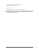
Chapter 5 How to update the BIOS. The SSD This chapter explains how to use the BTOOL Program and gives information about the Integrated Solid State Disk. Warning: The BTOOL Program can be different for each CPU and each BIOS version. For the last versions visit the site: www.parvus.com.
How to update the BIOS: the BTOOL Program The BTOOL program is a utility used to program the BIOS (that is stored in the Flash EPROM) in the following cases: ¾ BIOS upgrade; ¾ Installation of a MiniDOS compatible program into the Flash (Integrated SSD); ¾ Installation of a BIOS Extension into the Flash. PLEASE NOTE: BTOOL program must be run under MS-DOS environment, not DOS WINDOW, (so, if it is necessary, create a bootable floppy disk, with the command FORMAT/S.
OPTIONS EXPLANATION BTOOL /S BTOO L/L BTOOL /U BTOOL /G FILENAME (*) BTOOL /P FILENAME (*) BTOOL /B FILENAME (*) BTOOL /V FILENAME (*) BTOOL /U FILENAME (*) BTOOL /DA BTOOL /DB This option runs the Setup program without the necessity of rebooting the system and then pressing “F2” This option locks the setup. In this way the access to the Setup Program is denied. This option unlocks the setup. In this way the access to the Setup Program is re-established.
¾ The program will store the new BIOS version. ¾ Follow all the instructions the BTOOL gives you ¾ BTOOL will inform you about the results of the operation, ¾ Power off and then power on the CPU module. The Integrated Solid State Disk A portion of the Flash EPROM can be used as an Integrated SSD. This Integrated SSD is like a write-protected floppy disk for storing files. In the SpacePC 1232, the portion is 768 KB, and before enabling it needs to be written-to using the BTOOL program.
Chapter 6 Virtual Peripherals This chapter describes how to control the SpacePC 1232 module directly from a Laptop or a standard PC compatible computer: Use this mode when the PC/104 system doesn’t have I/O devices connected to it. The “Virtual Peripherals” mode The SpacePC 1232 module is designed to be used in industrial environments as a stand-alone module, independent from specific peripherals.
Local and redirected peripherals In “Virtual Peripherals” mode, two types of peripherals are used: ¾ The peripheral directly connected to the module (keyboard, video interface, SSD and floppy) named “local peripherals” ¾ The Host computer’s peripherals used for the remote control of the module (keyboard, video interface and Floppy) named “remote or redirected peripheral”.
CPU HOST COMPUTER PARALLEL PORT Parallel VP cable (*) SERIAL PORT 1 Serial VP cable (*) SERIAL PORT 2 VP adjustment (this end only) Short RTS1 with CTS1 (or DTR1 with RI1) for using VP mode with SERIAL1 Short RTS2 with CTS2 (or DTR2 with RI2) for using VP mode with SERIAL2 VP mode with Parallel DOESN’T NEED ANY SHORTs RTS CTS or DTR RI (*) This VP cables must be made observing the connections explained in the following tables = short circuit Figure 23. Table 22.
10,12,14,16, 18,20,22,24 18..25 GND GND 18..25 (*) The “#” stands for: signal active low Pins not included in the table above are not connected IMPORTANT NOTE: The VP2000 functionality performed via the parallel cable may not work with some host computers. It is important to set the host computer parallel port to "bi-directional". Start the VP2000.EXE program (you will find it in the CPU utility CD-ROM or in www.parvus.com tech support area) on the Host computer.
If you select the [/V] [/K] [/D] [/C] parameters, the VP connection will be performed according to the following rules: ¾ Only the selected remote peripherals are redirected in VP connection. ¾ The local peripherals connected are used according to the setup. ¾ If the floppy disks are redirected, it is not possible to use the local Host computer floppy for PC operations. ¾ The Boot is performed from the selected peripheral.
Chapter 7 Watchdog Timer This chapter describes the configuration of the Watchdog Timer with some examples. The watch dog is a part of the on–board SUPER I/O device SMSC FDC 37B782 The Super I/0 watchdog allows managing time-outs in order to seconds or minutes (depending on the Super I/O programming).
Watchdog modalities The watchdog function resets the board at the end of the countdown. There are two ways to program the watchdog: • • Using BIOS INT 52h Using direct Super I/O registers programming BIOS INT 52h - functions 0Ch, 0Dh, 0Eh This method can be used under DOS or under Operating Systems using the board BIOS (i.e. not under Linux which erases the BIOS after the boot and autonomously manage the module hardware).
MOV OUT AL, 55h DX, AL ; SPIO Configuration Mode Enable Key ; Enter in configuration mode ; Select Logical Device 8 (watch dog) ... MOV MOV OUT DX, 3F0h AL, 07h DX, AL ; SPIO Index Port ; Logical Device selector is the register 7 ; Point to Logical Device selector INC MOV OUT DX AL, 08h DX, AL ; SPIO Data Port ; Logical Device number 8 ; Select the Logical Device 8 ; Select the time base (seconds or minutes) ...
Watchdog time-out pin For external control purposes, the status of the watchdog time-out event is provided to connector J11 pin 9. This signal goes high when the watchdog resets the system. The software can reset this signal by setting and resetting bit 2 of the I/O port 110h. This signal is also initialized by hardware at power-on.
Chapter 8 Troubleshooting Many problems that you may encounter with operation of your SpacePC 1232 module are due to common errors like bad connections or wrong settings in the Setup Program. This chapter will help you for getting your system operating properly.
Common Problems and Solutions The following table lists some of the common problems that you may encounter while using your SpacePC 1232 module, and suggests possible solutions. If you are having problems with your SpacePC 1232 module, please review this table before contacting technical support. Table 24.
below 4.75V when hard drive or floppy drive starts, add bypass caps Add fan, processor heat sink, or other cooling device(s) Check for two hardware devices (e.g. Ethernet, SSD, PCMCIA) trying to use the same memory address Check for two software devices (e.g. EMM386, PCMCIA drivers, etc.
¾ Phone: 801-483-1533 ¾ Fax: 801-483-1523 If you have a sales question, please contact your local Parvus Sales Representative or the Regional Sales Office for your area. Additional and latest information is available at Parvus website: http://www.parvus.com Returning For Service Before returning any of Parvus' products, you must contact Parvus and obtain a Returned Material Authorization (RMA) number. Note.
Appendix A.1 Electrical and Environmental Specifications The following section provides tables and illustrations showing the electrical, mechanical and environmental specifications for the SpacePC 1232 module.
Note. In order to ensure proper operation and good reliability up to +60°C of ambient air temperature, the Geode GX1 chip and the Geode CS5530 I/O Companion are supplied with an attached passive heat sink. Battery Backup Characteristics There is no configuration data saved by the BIOS into the CMOS Real Time Clock. Therefore, the module does not need a battery except in the case of applications that need to hold the date and time at power-off. Note.
A.2 Mechanical Dimensions CPU Dimensions The SpacePC 1232 module’s mechanical dimensions are shown in the following picture: ¾ Dimensions: 90 X 96 mm (3.6”X3.8”), height:15 mm (0.6”) Dimensions are in millimeters Figure 24.
Note: For further information about the mechanical dimensions of ISA and PCI buses please refer to the pc104 consortium site (www.pc104.org) FDD Adapter Dimensions In the following picture are shown the FDD Adapter mechanical dimensions: Dimensions are in inches 43,6 6.5 2.4 13.0 4.7 1.4 3.0 1,5 12.7 6.3 41.
Dimensions are in millimeters Figure 25. FDD Adapter Dimensions USB Audio CODEC Dimensions In the following picture are shown the USB Audio CODEC mechanical dimensions: Dimensions are in inches 95.3 91.3 22.0 10.9 37.1 32.1 3.8 2.0 4.0 15.3 26.7 4.0 1.5 3.1 14.9 13.1 13.1 13.1 75.6 82.6 91.
USB Audio CODEC Dimensions Figure 26. USB Audio CODEC Dimensions Ethernet Adapter Dimensions In the following picture are shown the Ethernet Adapter mechanical dimensions: Dimensions are in inches 49.0 3.0 10.5 31.0 11.9 3.0 43.
Figure 27. Ethernet Adapter Dimensions Figure 28. Figure 29.
Figure 30. Multifunction Adapter Dimensions A.3 Safety Summary The following general safety precautions must be observed during all phases of operation, service, and repair of this equipment. Failure to comply with these precautions or with specific warnings elsewhere in this manual violates safety standards of design, manufacture, and intended use of the equipment. Parvus assumes no liability for the customer’s failure to comply with these requirements.
Do Not Substitute Parts or Modify Equipment Because of the danger of introducing additional hazards, do not install substitute parts or perform any unauthorized modification of the equipment. Contact Parvus technical staff or your local representative for service and repair to ensure that safety features are maintained. Flammability All Parvus PWBs (printed wiring boards) are manufactured by UL-recognized manufacturers, with a flammability rating of UL-V0.
Any reference to a licensed program in this publication is not intended to state or imply that you can use only that licensed program. You can use any functionally equivalent program instead. No part of this material may be reproduced or copied in any tangible medium, or stored in a retrieval system, or transmitted in any form or by any means, radio, electronic, mechanical, photocopying, recording or facsimile, or otherwise, without the prior written permission of Parvus.
Acronyms and Abbreviations ACPI AGP APM ATA ATAPI BIOS CRT DDC DDC2B DMA DSTN ECC ECP FAT FDC FDD FDDI FIFO FM fps GSM HDC HDD IDE IEEE I/O IP IRQ ISA KB Kbps KHz LAN LBA LCD LPT Advanced Configuration and Power Interface Accelerated Graphic Port Advanced Power Management AT Attachment ATA Packet Interface Basic I/O System Cathode Ray Tube Display Data Channel DDC Standard, Version 2.
For more information about this or other products in the Parvus line of embedded development tools and control systems call (801) 483-1533 from 8:00AM to 5:00PM Mountain Time, E-mail us at parvus@parvus.com or visit our web-site at: http://www.parvus.com LIMITED WARRANTY Parvus Corporation warrants this product to be free of defects in materials and workmanship, and that the product meets or exceeds the current specifications published by Parvus.
For further information contact: Parvus® Corporation 3222 S. Washington St. Salt Lake City, Utah, USA 84115 (801) 483-1533, FAX (801) 483-1523 Web-site: http://www.parvus.com Email: parvus@parvus.