SMCWHSG44-G
1
Copyright Information furnished by SMC Networks, Inc. (SMC) is believed to be accurate and reliable. How-ever, no responsibility is assumed by SMC for its use, nor for any infringements of patents or other rights of third parties which may result from its use. No license is granted by implication or otherwise under any patent or patent rights of SMC. SMC reserves the right to change specifications at any time without notice. Copyright © 2004 by SMC Networks, Inc.
LIMITED WARRANTY Limited Warranty Statement: SMC Networks, Inc. (“SMC”) warrants its products to be free from defects in workmanship and materials, under normal use and service, for the applicable warranty term. All SMC products carry a standard 90-day limited warranty from the date of purchase from SMC or its Authorized Reseller. SMC may, at its own discretion, repair or replace any product not operating as warranted with a similar or functionally equivalent product, during the applicable warranty term.
WARRANTIES EXCLUSIVE: IF AN SMC PRODUCT DOES NOT OPERATE AS WARRANTED ABOVE, CUSTOMER'S SOLE REMEDY SHALL BE REPAIR OR REPLACEMENT OF THE PRODUCT IN QUESTION, AT SMC'S OPTION. THE FOREGOING WARRANTIES AND REMEDIES ARE EXCLUSIVE AND ARE IN LIEU OF ALL OTHER WARRANTIES OR CONDITIONS, EXPRESS OR IMPLIED, EITHER IN FACT OR BY OPERATION OF LAW, STATUTORY OR OTHERWISE, INCLUDING WARRANTIES OR CONDITIONS OF MERCHANTABILITY AND FITNESS FOR A PARTICULAR PURPOSE.
Federal Communication Commission Interference Statement This equipment has been tested and found to comply with the limits for a Class B digital device, pursuant to Part 15 of the FCC Rules. These limits are designed to provide reasonable protection against harmful interference in a residential installation. This equipment generates, uses and can radiated radio frequency energy and, if not installed and used in accordance with the instructions, may cause harmful interference to radio communications.
EC Conformance Declaration SMC contact for these products in Europe is: SMC Networks Spain S.L., Edificio Conata II, Calle Fructuós Gelabert 6-8, 2o, 4a, 08970 - Sant Joan Despí, Barcelona, Spain. Signed and dated Copy of the Declaration of Conformity can be found in the product section of www.smc-europe.com This RF product complies with R&TTE Directive 99/5/EC.
• • • • to other system. The user is obligated to ensure the device is operating according to the channel limitations, indoor/outdoor restrictions and license requirements for each European Community country as described in this document. This device may be operated indoors or outdoors in all countries of the European Community using the 2.4 GHz band: Channels 1 - 13, except where noted below.
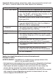
Important! Before making connections, make sure you have the correct cord set. Check it (read the label on the cable) against the following: Power Cord Set U.S.A. and Canada The cord set must be UL-approved and CSA certified. The minimum specifications for the flexible cord are: - No. 18 AWG - not longer than 2 meters, or 16 AWG.
• La prise secteur doit se trouver à proximité de l'appareil et son accès doit être facile. Vous ne pouvez mettre l'appareil hors circuit qu'en débranchant son cordon électrique au niveau de cette prise. • L'appareil fonctionne à une tension extrêmement basse de sécurité qui est conforme à la norme IEC 60950. Ces conditions ne sont maintenues que si l'équipement auquel il est raccordé fonctionne dans les mêmes conditions.
Wichtige Sicherheitshinweise (Germany) 1. Bitte lesen Sie diese Hinweise sorgfältig durch. 2. Heben Sie diese Anleitung für den späteren Gebrauch auf. 3. Vor jedem Reinigen ist das Gerät vom Stromnetz zu trennen. Verwenden Sie keine Flüs-sigoder Aerosolreiniger. Am besten eignet sich ein angefeuchtetes Tuch zur Reinigung. 4. Die Netzanschlu ßsteckdose soll nahe dem Gerät angebracht und leicht zugänglich sein. 5. Das Gerät ist vor Feuchtigkeit zu schützen. 6.
Der arbeitsplatzbezogene Schalldruckpegel nach DIN 45 635 Teil 1000 beträgt 70dB(A) oder weniger. Stromkabel. Dies muss von dem Land, in dem es be-nutzt wird geprüft werden: U.S.A und Canada Der Cord muß das UL gepruft und war das CSA beglaubigt. Das Minimum spezifikation fur der Cord sind: - Nu. 18 AWG - nicht mehr als 2 meter, oder 16 AWG.
12
Table of Contents 1. Introduction 17 1.1. Overview 18 1.2. Features 18 1.2.1 Package Checklist 22 1.3. LED Definition 22 1.4. Rear Panel 22 1.5. Selecting a Power Supply Method 23 1.6. Mounting the SMCWHSG44-G on a Wall 24 1.7. Preparing for Configuration 25 1.7.1. Connecting the Managing Computer and the SMCWHSG44-G 25 1.7.2. Changing the TCP/IP Settings of the Managing Computer 25 1.8. Configuring the SMCWHSG44-G 26 1.8.1. Entering the Password 26 1.8.2.
1.11. Confirming the Settings of the SMCWHSG44-G and Client Computers 40 2. Using Web-Based Network Manager 42 2.1. Overview 42 2.1.1. Menu Structure 42 2.1.2. Save, Save & Restart, and Cancel Commands 44 2.1.3. Home and Refresh Commands 44 2.2. Status 44 2.2.1. Associated Wireless Clients 44 2.2.2. Authenticated Users 45 2.2.3. Account Table 45 2.2.4. Session List 46 2.2.5. Managed LAN Devices 46 2.3. SYSTEM 47 2.3.1. Specifying Operational Mode 47 2.3.2.
2.4.3.1. Basic 57 2.4.3.2. Virtual Server Mappings 58 2.4.4. DHCP Server 58 2.4.4.1. DHCP Server 59 i. Basic 59 ii. Static DHCP Mappings 59 2.4.4.2. DHCP Relay 60 2.4.5. Load Balancing 60 2.4.6. Zero Client Reconfiguration 61 2.5. Configuring IEEE 802.11-Related Settings 61 2.5.1. Wireless 61 2.5.1.1. Basic 61 2.5.1.2. Wireless Distribution System 62 2.5.2. Security 64 2.5.2.1. Basic 64 2.5.2.2. MAC-Address-Based Access Control 66 2.5.3. IEEE 802.1x/RADIUS 67 2.6.
2.8.1.2. VLAN 79 2.8.1.3. Firewall 79 2.8.1.4. URL Filters 80 2.8.2. Management 80 2.8.2.1. Basic 80 2.8.2.2. UPnP 81 2.8.2.3. System Log 81 2.8.2.4. SNMP 82 2.8.3. Access Rules 82 2.8.4.
1. Introduction The EliteConnect 2.4GHz 802.11g Wireless Hotspot Gateway (SMCWHSG44-G) enables VARs, WISPs and System Integrators to install secure, easy to manage Hotspots as a one-box solution.
1.1. Overview 1.2. Features • User Authentication, Authorization, and Accounting (AAA) • Web redirection - When an unauthenticated wireless user is trying to access a Web page, he/she is redirected to a logon page for entering the user name and password. Then, the user credential information is sent to a back-end RADIUS server for authentication or via the Local Authentication Database.
• 64-bit and 128-bit WEP (Wired Equivalent Privacy) - For authentication and data encryption. • Enable/Disable SSID broadcast - The user can enable or disable the SSID broadcasts functionality for security reasons. When the SSID broadcast functionality is disabled, a client computer cannot associate with the wireless AP with an “any” network name (SSID, Service Set ID); the correct SSID has to be specified on client computers.
• • • • • Virtual server - Exposing servers on the intranet to the Internet. • PPTP, IPSec, and L2TP pass-through - Passing VPN (Virtual Private Network) packets through the intranet-Internet boundary. PPTP means Point-to-Point Tunneling Protocol, IPSec means IP Security, and L2TP means Layer 2 Tunneling Protocol. • DMZ (DeMilitarized Zone) - All unrecognized IP packets from the Internet can be forwarded to a specific computer on the intranet.
• SNTP - Support for system time by SNTP (Simple Network Time Protocol). • Dynamic DNS - Support for dynamic DNS services provided by dyndns.org and no-ip.com, so that the SMCWHSG44-G can be associated with a domain name even if it obtains an IP address dynamically by PPP, PPPoE or DHCP. • LAN Device Management - The Wireless Hotspot Gateway can pass management requests from the Internet through its built-in NAT server to devices on the private network.
• Configuration Reset - Reset the configuration settings to factory-set values. 1.2.1 Package Checklist * Check that you have the following contents in the box: • SMCWHSG44-G Wireless Hotspot Gateway • User Guide • Utility & Documentation CD • Wallmount Kit • Power Adapter • 2 dBi Dipole Antenna 1.3. LED Definition • • • • PWR : Power ALIVE : Blinks when the SMCWHSG44-G is working normally. RF : IEEE 802.11b/g interface activity WAN/LAN : Ethernet WAN/LAN interface activity Fig. 1. LED Indicator 1.4.
1.5. Selecting a Power Supply Method The SMCWHSG44-G can be powered by either the supplied AC power adapter or the optional SMCPWR-INJ3 EliteConnect™ Power Injector. The SMCWHSG44-G automatically selects the suitable power depending on your decision. To power the SMCWHSG44-G by the supplied power adapter: 1. Plug the power adapter to an AC socket. 2. Plug the connector of the power adapter to the power jack of the SMCWHSG44-G.
Fig. 5. Connecting Ethernet cables to SMCPWR-INJ3. 5. Check the “ACTIVE” LED: if power is successfully fed into the SMCWHSG44-G, the “ACTIVE” LED will be on (Red light); otherwise, the “ACTIVE” LED will be off. 6. If the electricity current is over the normal condition (Io°÷1.0 A), the “ACTIVE” LED will flash (Red light). NOTE: SMCPWR-INJ3 is specially designed for SMC2582W-B, SMC2586W-G, and SMCWHSG44-G. The use of SMCPWR-INJ3 with other Ethernet-ready devices that are not compliant to IEEE 802.
1.7. Preparing for Configuration To configure the Wireless Hotspot Gateway, a managing computer with a Web browser is needed. For first-time configuration of a SMCWHSG44-G, an Ethernet network interface card (NIC) should have been installed in the managing computer. For maintenance/configuration of a deployed SMCWHSG44-G, either a wireless computer or a wired computer can be employed as the managing computer.
address of the computer to 192.168.2.xxx (the default IP address of the SMCWHSG44-G is 192.168.2.1) and the subnet mask to 255.255.255.0.) It is preferred to set the computer to “obtain an IP address automatically” so the router will give your computer the correct settings automatically. NOTE: For some versions of Windows, the computer needs to be restarted for the changes of TCP/IP settings to take effect. 1.8. Configuring the SMCWHSG44-G The SMCWHSG44-G is DHCP server enabled by default.
Fig. 10. Home Page. 1.8.2. SETUP WIZARD Step 1: Selecting an Operational Mode Fig. 11. Operational Modes. • If the Router is to be used with a DSL or cable modem and the IP address assignment for the Ethernet WAN interface is achieved by PPPoE, select Router with a PPPoE-Based DSL/Cable Connection. • If the Router is to be used with a DSL or cable modem and the IP address assignment for the Ethernet WAN interface is achieved by DHCP, select Router with a DHCP-Based DSL/Cable Connection.
of the Ethernet WAN interface has to be manually set, select Router with a Static-IP DSL/Cable Connection. • If you have multiple ADSL/cable connections, select Router with n DSL/Cable Connections. Select the number of connections using the drop-down list, and then specify the type, downlink date rate and uplink data rate of each ADSL/cable connection. The specified data rates affect the load-balancing engine of the SMCWHSG44-G. 1.8.3. SETUP WIZARD Step 2: Configuring TCP/IP Settings 1.8.3.1.
1.8.3.2. Router with a DHCP-Based DSL/Cable Connection Fig. 13. TCP/IP settings for Router with a DHCP-Based DSL/Cable Connection mode. If the SMCWHSG44-G is set to be in 'Router with a DHCP-Based DSL/Cable Connection 'mode, two IP addresses are needed-one for the Ethernet LAN interface and the other for the WAN interface. The LAN IP address must be set manually to a private IP address, say 192.168.2.xxx. The default LAN IP address is 192.168.2.1 and the default subnet mask is 255.255.255.0.
address is 192.168.2.1 and the default subnet mask is 255.255.255.0. In most cases, these default settings need no change. As for the WAN IP address, it must be manually set. Consult your ISP for the correct IP address, Default gateway, Subnet mask, Primary DNS server, and Secondary DNS server settings. 1.8.3.4. Router with Multiple DSL/Cable Connections Fig. 15. TCP/IP settings for Router with Multiple DSL/Cable Connections mode.
1.8.4. SETUP WIZARD Step 3: Configuring DHCP Server Settings Fig. 16. DHCP Server Settings. The SMCWHSG44-G can automatically assign IP addresses to client computers by DHCP. DHCP server settings include Default gateway, Subnet mask, Primary DNS server, and Secondary DNS server. Additionally, you can specify the first IP address that will be assigned to the clients and the number of allocatable IP addresses.
The number of available RF channels depends on local regulations; therefore you have to choose an appropriate regulatory domain to comply with local regulations. The SSID of a wireless client computer and the SSID of the wireless Hotspot gateway must be identical for them to communicate with each other. Note: SMCWHSG44-Gs sold in North America and EMEA are already configured to FCC and ETSI domain respectively, and the domain settings are not able to be changed. 1.8.6.
Authentication protocol: RADIUS: Authentication by external RADIUS server. Local Accounts: Authentication by local database, associated with ticket printing or manually configured users. RADIUS authentication method: EAP-MD5 PAP CHAP 2. Enabled without Authentication - Enables only the Web-Redirection, but disables the user Authentication mechanism. Users will automatically redirect to the destination web page of the URL indicated. Fig. 20. Web Redirection Settings - Enable without Authentication 3.
• Amount of Money Per Unit: defines the money to be charged per unit. • Unit of Session time (min): defines the time frame (by min) for the user to access the Internet. Default is '1' min. For example: x number of minutes = 1 Unit of Session Time • Valid period (hour): to define the valid period (by hour) while the user account is generated. If the user account is generated but not activated during the valid period, the gateway will automatically disable the user after the valid period expired.
Fig. 24. Account Table List 1.8.6.3. How to Setup the Mini-POS Ticket Printer The SMCWHSG44-G supports a built-in user database for local authentication. This function also associates with the external Mini-POS Ticket Printer (SMCWHS-POS) for billing and printing purposes. The benefit of the built-in user database is to provide a local user authentication database as some Hotspot venues do not have the capability to setup a complete RADIUS environment for user authentication.
Unit” and a value for the number of minutes for “Units of Session time”. In order to produce a ticket from the Mini-POS Ticket Printer, you will need to key in selected numbers, and press ENTER. The numbers you select on the keypad will always correspond to the Units of Session Time. • For Example: You have assigned “3” as the value for the Amount of Money Per Unit. You have assigned “30” as the number of minutes equal to 1 Unit of Session Time.
1.8.6.5 Configuring RADIUS Settings The RADIUS client on the SMCWHSG44-G works in conjunction with the Web redirection component and IEEE 802.1x component for wireless user authentication. The Web redirection and IEEE 802.1x components are responsible for acquiring user credential information, and the RADIUS client communicates with a back-end RADIUS server using the user credential information. Go to the AAA\RADIUS section (see section 2.6.2), and then configure the RADIUS settings.
1.9. Deploying the SMCWHSG44-G After the settings have been configured, deploy the Wireless Hotspot Gateway to the field application environment. The system configuration in Fig. 28 illustrates how to deploy the SMCWHSG44-G. In this configuration, one DSL/cable modem is connected to the WAN port (as WAN 1) of the SMCWHSG44-G and another modem is connected to the LAN 1 port (as WAN 2) of the SMCWHSG44-G. Two APs are connected to the LAN 2 port and LAN 3 port, respectively.
name and password information must be set up on the RADIUS server or Locally on the Wireless Hotspot Gateway. On the other hand, if IEEE 802.1x EAP-TLS authentication method is used, a digital certificate must be installed on the computer or PDA and on the back end RADIUS server. 1.10.1. Configuring IEEE 802.
current IP address and reobtaining an IP address. IPConfig.exe is a command-line program, and the /release option releases the current IP address and the /renew option triggers the Windows DHCP client subsystem to re-obtain an IP address. 1.11. Confirming the Settings of the SMCWHSG44-G and Client Computers To make sure you have correctly set up the SMCWHSG44-G for Web redirection-based authentication or not, follow the procedure below: 1.
Fig. 31. Authentication Success. Fig. 32. Log-Off Window. 6. Click Log Off within the log-off window to end the session. NOTE: On a PDA such as Pocket PC, the log-off would not be shown. To log off from the network, go back to the Log-on page, and then click Log Off to end the session. 7. If the user name or password is invalid, you will be prompted to try again or cancel the authentication process. Fig. 33. Authentication Failure. NOTE: If IEEE 802.
2. Using Web-Based Network Manager In this section, we will explain each Web management page of the Web-based Network Manager in detail. 2.1. Overview Fig. 34. Home Page. 2.1.1. Menu Structure The left side of the start page contains a menu for you to carry out commands. Here is a brief description of the hyperlinks on the menu: • Home. For going back to the start page. • Current Time. • System Up Time. • Internet Information. • Gateway Information. • System Information. • DHCP Client.
• • • • • • • Firmware Tools. For upgrading the firmware of the Router and backing up and restoring configuration settings. • Time Zone. Time zone and SNTP (Simple Network Time Protocol) server settings. TCP/IP. TCP/IP-related settings. • Address. IP addressing settings for the Router to work with your ISP, user name and password provided by the ISP and LAN settings • DNS. DNS (Domain Name System) proxy settings. • NAT. Virtual Server, DMZ and session control settings. • DHCP Server.
authenticated by SMCWHSG44-G. Authenticated users can also be terminated in this table. • Account Table. Manually generates new users, or is automatically populated with accounts after entering amount of time required via the keypad. • Session list. Display the status of session traffic • Managed LAN Devices. Display the status of local LAN devices connected to the Wireless Hotspot Gateway. 2.1.2. Save, Save & Restart, and Cancel Commands Fig. 35. Save, Save & Restart, and Cancel.
2.2.2. Authenticated Users Fig. 38. Authenticated Users. On this page, the status information of each authenticated user, including its current idle time, user name, IP address, MAC address, and status, is shown. In addition, you can click the Detail link in the Statistics column to see more detailed statistics information, such as Input packets, Output packets, Input bytes, and Output bytes. Fig. 39. Authenticated RADIUS User Detailed Information.
On this page, all the registered users in local user database are shown. An activated user is identified by its MAC address, login time and the 'Active' display under the 'Status' column. 2.2.4. Session List Fig. 42. Latest Outgoing User Traffic Sessions. Fig. 43. Latest Incoming User Traffic Sessions. On this page, latest 50 outgoing and 50 incoming user traffic sessions are shown for monitoring net-work activity. 2.2.5. Managed LAN Devices Fig. 44. Managed LAN devices.
2.3. SYSTEM 2.3.1. Specifying Operational Mode Fig. 44. Operational Modes. On this page, you can specify the operational mode for the Router. Currently, 5 modes are available: • Router with a PPPoE-based DSL/Cable Connection. In this mode, the Router assumes that a DSL or cable modem is connected to its Ethernet WAN interface. The client computers can therefore share this DSL/cablebased Internet connection by the NAT server functionality.
NOTE: When the Router is in Router with Multiple DSL/Cable Connections mode, connect your first DSL/Cable connection to WAN, the second to LAN 1, the third to LAN 2, and the fourth to LAN 3. Then, WAN becomes WAN 1, LAN 1 becomes WAN 2, LAN 2 becomes WAN 3, and LAN 3 becomes WAN 4 when referred to on the Web management pages. Fig. 45. WAN Port IDs. TIP: After you have selected the operational mode of the Router, go to the TCP/IP, Addressing section of the management UI (see Section 2.4.
with some Web browsers. If you cannot successfully perform HTTP-based firmware management operations with your Web browser, try the TFTPbased way. 2.3.3.1. Upgrading Firmware by HTTP Fig. 48. Firmware Upgrade by HTTP. To upgrade firmware of the SMCWHSG44-G by HTTP: 1. Click Browse and then select a correct firmware .bin file. The firmware file path will be shown in the Firmware file name text box. 2. Click Upgrade to begin the upgrade process. 2.3.3.2.
2.3.3.3. Upgrading Firmware by TFTP Fig. 51. TFTP Server Settings. When using TFTP as the firmware management protocol, you can configure settings for the SMCWHSG44-G's TFTP client to communicate with a TFTP server. If the TFTP client does not get a response from the TFTP server within a period specified by the Timeout setting, it will resend the previous request. The Max number of retries setting specifies the maximal number of resend before the TFTP client stops communicating with the TFTP server.
Fig. 53. TFTP Server. NOTE: After the dialog box of the TFTP server program appears, be sure to specify the working folder within which the downloaded firmware files reside. NOTE: Make sure the Accept read requests check box of TFTP Server is selected. NOTE: The LAN IP address of the SMCWHSG44-G and the IP address of the TFTP server must be in the same IP subnet for TFTP to work.
2. Connect the computer and one of the LAN Ethernet switch port with a normal Ethernet cable. 3. Configure the IP address of the computer so that the computer and the SMCWHSG44-G are in the same IP subnet. 4. On the computer, run the TFTP Server utility. Select the Accept write requests check box, and specify the folder to which the configuration settings of the Router will be saved. 5. On the computer, run a Web browser and click the SYSTEM\Firmware Tools hyperlink. 6.
2.3.3.5. Resetting Configuration to Factory Defaults Fig. 55. Configuration Reset. Clicking the Reset button resets the device configuration to factory defaults. WARNING: Once you click Reset you will lose all your current configuration settings. 2.3.4. Time Zone Fig. 56. Time Zone and Time Server Settings. The SMCWHSG44-G supports system time by querying the SNTP (Simple Network Time Protocol) time server specified by the Time server setting.
If the SMCWHSG44-G was set to be in Router with a PPPoE-Based DSL/Cable Connection mode, two IP addresses are needed: one for the Ethernet LAN interface and the other for the WAN interface. The LAN IP address must be set manually to a private IP address, say 192.168.0.xxx. The default LAN IP address is 192.168.2.1 and the default subnet mask is 255.255.255.0. In most cases, these default settings need no change. As for the WAN IP address, it is obtained automatically by PPPoE from the ISP.
As for the WAN IP address, it is obtained by DHCP from the ISP. The Trigger mode setting affects the behavior of the DHCP client of the Router. In Auto mode, you don't have to worry about the DHCP process; the device takes care of everything. In Manual mode, there are two buttons on the Start page for you to manually release an obtained IP address (Release) and reobtain a new one from a DHCP server (Renew). “Big Pond Settings” is the settings for service of Telstra, Australia.
2.4.1.4. Router with Multiple DSL/Cable Connections Fig. 60. TCP/IP Settings for Router with Multiple DSL/Cable Connections Mode. Since the Internet connection can be PPPoE-based, DHCP-based, or StaticIP-based, the addressing settings of each WAN interface are the same as those of Router with a PPPoE-Based DSL/Cable Connection, DHCP-Based DSL/Cable Connection, or Router with a Static-IP DSL/Cable Connection, respectively. As a result, refer to previous sections for more information. 2.4.2. DNS 2.4.2.1.
Fig. 61. DNS Proxy under Multi-WAN Mode. 2.4.2.2. Host Address Resolution Fig. 62. Host Address Resolution Mappings. The SMCWHSG44-G provides the Host Address Resolution to provide the local DNS server capability. The Host Address Resolution (local DNS server) function of SMCWHSG44-G will respond to the DNS request of wireless clients and reply the requested destination IP address.
A DMZ (DeMilitarized Zone) host receives all unrecognized TCP/IP packets from the NAT server on the Router; therefore TCP/IP networking applications running on the DMZ host would have better compatibility with NAT. To specify the DMZ host: • Enter the private IP address of the computer to be used as a DMZ host, and select the corresponding check box. 2.4.3.2. Virtual Server Mappings Fig. 64. Virtual Server Mappings.
2.4.4.1. DHCP Server i. Basic Fig. 65. Basic DHCP server settings. The SMCWHSG44-G can automatically assign IP addresses to client computers by DHCP. In this section of the management page, you can specify the Default gateway, Subnet mask, Primary DNS server, and Secondary DNS server settings that will be sent to a client at its request. Additionally, you can specify the first IP address that will be assigned to the clients and the number of allocatable IP addresses.
To always assign an IP address to a specific DHCP client: 1. Specify the MAC address of the DHCP client and the IP address to be assigned to it. Then, give a description for this mapping. 2. Select the corresponding Enabled check box. 2.4.4.2. DHCP Relay When the DHCP server functionality is set to “DHCP Relay”, the SMCWHSG44 won't assign the IP address to the clients. It will forward the received DHCP requests from the clients to the designate DHCP server.
Fig. 69. Load Balancing Policy Settings. 2.4.6. Zero Client Reconfiguration Fig. 70. Zero Client Reconfiguration Settings. The SMCWHSG44-G provides the 'Zero Client Reconfiguration' function to allow the wireless clients that associate to the SMCWHSG44-G the ability to not make any network setting modifications. This feature is useful in case users already have static IP information or IP addressing set for another network.
client can associate with the SMCWHSG44-G. The Policy setting allows you to run in mode, B only or G only. In mixed mode both 802.11b and 802.11g clients are able to connect. In B only mode only 802.11b clients can connect, and in G only mode only 802.11g clients will be able to connect wirelessly to the gateway. The number of available RF channels depends on local regulations; therefore you have to choose an appropriate regulatory domain to comply with local regulations.
notebook computers. In this way, the SMCWHSG44-G plays a role of “AP repeater.” NOTE: The SMCWHSG44-G can have up to 6 WDS links to other wireless AP/bridge. Fig. 73. Wireless Distribution System Settings. To enable a WDS link: 1. Specify the MAC address of the AP or wireless bridge at the other end of the WDS link. 2. Select the corresponding Enabled check box.
Fig. 75. Network Topology Containing a Loop. 2.5.2. Security IEEE 802.11b/g security settings include SSID broadcasts, Client Isolation, IEEE 802.11 Authentication algorithm, WEP, WPA, and MAC-Address-Based Access Control. 2.5.2.1. Basic Fig. 76. Basic IEEE 802.11g Security Settings. For security reasons, it's highly recommended that the security mode be set to options other than Open System. When the security mode is set to Open System, no authentication and data encryption will be performed.
When the setting is set to "All APs in This Subnet", traffic among wireless users of different SMCWHSG44-Gs in the same IP subnet is blocked. The behaviors are illustrated in the following figures. Fig. 77. Behavior of the “This AP Only” Wireless Client Isolation Option. Fig. 78. Behavior of the “All APs on This Subnet” Wireless Client Isolation Option. As illustrated in Fig.
NOTE: The number of characters of the Pre-shared key setting must be at least 8 and can be up to 63. • IEEE 802.1x EAP without Encryption (EAP-MD5). The IEEE 802.1x functionality is enabled and the user-name/password-based EAP-MD5 authentication is used. No data encryption. • IEEE 802.1x EAP with Static WEP (EAP-MD5). The IEEE 802.1x functionality is enabled and the user-name/password-based EAP-MD5 authentication is used. Data encryption is achieved by static WEP. • IEEE 802.
With MAC-Address-Based Access Control, you can specify the wireless clients (STAs or Bridge Slaves) that are permitted or not permitted to associate with the SMCWHSG44-G. When the table type is set to inclusive, entries in the table are permitted to associate and all other users are blocked. When the table type is set to exclusive, entries in the table are not permitted to associate with the SMCWHSG44-G while other users are allowed access. To deny wireless clients' access to the wireless network: 1.
stored in the computer hard disk or a smart card for authentication. And after a successful EAP-TLS authentication, a session key is automatically generated for wireless packets encryption between the wireless client computer and its associated wireless access point. To sum up, EAP-MD5 supports only user authentication, while EAP-TLS supports user authentication as well as dynamic encryption key distribution. Fig. 80. IEEE 802.1x and RADIUS. The SMCWHSG44-G supports IEEE 802.
2.6. Configuring Authentication Settings The SMCWHSG44-G supports both IEEE 802.1x-based and Web redirection-based user authentication. Here is a brief description of how Web redirection works: When an unauthenticated wireless user is trying to access a Web page, a logon page is shown instead of the requested page, so that the user can type his/her user name and password for authentication.
2.6.1. AAA 2.6.1.1. Basic Fig. 83. Web-Redirection Enabled with Authentication. There are three modes for Web redirection-Enabled with Authentication, Enabled without Authentication, and Disabled. In Enabled with Authentication mode, you have two options. Radius Authenticaion or Local Authentication built into the SMCWHS44-G. Currently for Radius Authentication EAP-MD5, PAP, and CHAP are supported.
Fig. 85. Default Log-Off Page. NOTE: On a PDA such as Pocket PC, the log-off would not be shown. To log off from the network, go back to the log-on page, and then click Log Off to end the session. If the user fails the authentication, the user can be brought to a default warning page (Default page) or a page for the user to subscribe a wireless Internet access service (The following URL). Fig. 86. Default Authentication Failure Warning Page.
2.6.1.2. Unrestricted Clients Fig. 88. Unrestricted Clients Settings. There are occasions on which you want some computers to be able to freely access the Internet without being authenticated first. For example, you may want your wired desktop computers connected with the SMCWHSG44-G to be uncontrolled while providing wireless Internet access service for your customers with wireless laptop computers. The Unrestricted Clients feature is for this purpose.
2.6.1.3. Walled Garden Fig. 89. Walled Garden Settings. IP addresses or URLs in the walled garden can be accessed without authentication. This feature is useful for WISPs to do advertisement. For example, a WISP can set up a Web server to contain advertisement information for users who have not subscribed to its wireless Internet service. The walled garden links are shown on the log-on authentication page. To add a link to the walled garden: 1. Describe this link in the Prompt text box. 2.
For the SMCWHSG44-G, the RADIUS client component of the Router is shared by the IEEE 802.1x and Web redirection components. The RADIUS settings are for the RADIUS client to communicate with backend RADIUS servers. NOTE: When configured for EAP authentication, the RADIUS server supports either EAP-TLS or EAP-MD5, but not both at the same time. As a result, not all combinations of EAP-MD5, EAP-TLS, PAP and CHAP authentication methods are available if both IEEE 802.1x and Web redirection are enabled.
2.6.3. Authentication Session Control Fig. 92. Authentication Session Control Settings. Authentication session control settings are for controlling the lifetimes of user authentication sessions. The Idle timeout setting specifies how long a user can be idle without generating any traffic before being terminated. The Session timeout setting specifies the maximum session lifetime.
Fig. 94. Authentication Success Page Customization Settings. Fig. 95. Authentication Failure Page Customization Settings. In addition to the Text alignment, HTML title, and Contents setting, two more settings are provided for specifying the size of the Log-Off window (Windows width and Window height). Fig. 96. Log-Off Page Customization Settings. Furthermore, Banner images and Hyperlinks can be added to the Log-Off window for advertisement purposes.
Fig. 97. Advertisement Links Settings. Fig. 98. Advertisement Links in Action. 2.7. DDNS Fig. 99. Dynamic DNS Settings. With the help of dynamic DNS (DDNS) services provided by dyndns.org or no-ip.com, you can make your device automatically register the IP address it obtains dynamically by PPPoE or DHCP with the DDNS servers. DDNS is useful if you want to set up a Web server whose IP address is dynamically obtained rather than statically configured.
2.8. Configuring Advanced Settings 2.8.1. Filters and Firewall 2.8.1.1. Packet Filters Fig. 100. Packet Filters Settings. You can specify rules for the firewall component of the Router to check outgoing packets. Packets that meet the rules can be permitted or denied. The protocol field, source IP address field, destination IP address field, and destination port field of a packet's IP header are inspected to see if it meets a rule.
To set a rule for packet filtering: 1. Specify the protocol type, source IP address, source IP mask, destination IP address, destination IP mask, and destination port for the rule. Then specify in the Action setting how to deal with a packet that meets the rule. 2. Select the corresponding Enabled check box. NOTE: Set the rules with great care since incorrect rules would make the Router inaccessible.
2.8.1.4. URL Filters Fig. 103. URL Filters Settings. The SMCWHSG44-G is capable of blocking HTTP traffic from the intranet to specified unwelcome Web sites. To block HTTP traffic to an unwelcome Web site: 1. Specify the URL (ex. www.xxx.com) of the unwelcome Web site. 2. Select the corresponding Enabled check box. 2.8.2. Management 2.8.2.1. Basic Fig. 104. Web-Based Management Setting.
2. Type the Starting IP address and the End IP Address of the host IP address range. 3. Select the corresponding check box next to the IP address range. 2.8.2.2. UPnP Fig. 105. UPnP Settings. UPnP (Universal Plug and Play) enables a Windows XP user to automatically discover peripheral devices by HTTP. When the UPnP functionality is enabled, you can see the Router in My Network Places of Windows XP. The Router can be given a name that will be shown in My Network Places.
2.8.2.4. SNMP Fig. 107. SNMP Settings. The SMCWHSG44-G can be managed by SNMP (Simple Network Management Protocol). You can specify the name (used as a password) of the read-only and read-write community. In addition, up to 5 SNMP trap targets can be set in the SNMP Trap table. To specify a trap target: 1. Type the IP address of the target host. 2. Type the Community for the host. 3. Select the corresponding check box next to the IP address text box. 2.8.3. Access Rules Fig. 109. Access Rules Settings.
3. The 'Denied' columns can be also specified by selecting the head of lines (time) or columns (date). Wireless users cannot access the internet resources in the specified date/time columns. For example, see Fig. 105, the specified columns mean 'Wireless users are not allowed to access the Internet every Monday and 02:00 ~ 04:00 Sunday through Saturday. With Unrestricted Host, you can specify the MAC address of wireless clients that are permitted to access the Internet within the Access Rule defined period.
and Device Port. In other words, this request is passed through the built-in NAT server of the Router and routed to the corresponding man-aged LAN device. For example, Fig. 111 illustrates a LAN device management scenario based on the settings values in Fig. 110. AP1 can be managed from the management server by using a Web browser and a URL “http://61.16.31.110:60001”. AP2 can be managed by using a Web browser and a URL “http://61.16.31.110:60002”.
Appendix A A-1: Default Settings TIP: Press the reset button of a powered-on Router to reset the configuration settings to factory-set values.
A-2: LED Definitions There are several LED indicators on the housing of a Router. They are defined as follows: • • • • PWR ALV RF WAN/LAN : Power : Alive. Blinks when the SMCWHSG44-G is working normally. : IEEE 802.11b/g interface activity : Ethernet WAN/LAN interface activity Appendix B: Troubleshooting Check the following first: • Make sure that the power of the Router is on and the Ethernet cables are connected firmly to the RJ-45 jacks of the Router.
B-1: TCP/IP Setting Problems Fig. 113. Communication Stages for A Client to Reach its Correspondent Host. For a client computer to communicate with a correspondent host on the Internet by the host's domain name (e.g. http://www.smc.com), it first sends a DNS request to a DNS server on the Internet. The DNS request travels first to the SMCWHSG44-G, then the SMCWHSG44-G relays this request to the default gateway of the SMCWHSG44-G through a modem.
• • • • • Check if the RADIUS server is set to use EAP-MD5, PAP, and CHAP authentication. The SMCWHSG44-G does not respond to ping from the client computer. • Are two or more NICs (wireless or wired) installed on the client computer? • Use Windows-provided Device Manager to disable unnecessary NICs. • Is the underlying communication link established? • Make sure the wireless link is OK. • Make sure the Ethernet link between the AP and the SMCWHSG44-G is OK.
B-2: Wireless Settings Problems • The wireless client computer cannot associate with an SMCWHSG44-G. • Is the wireless client set in infrastructure mode? • Check the operating mode of the WLAN NIC. • Is the SSID of the WLAN NIC identical to that of the prospective SMCWHSG44-G? • Check the SSID setting of the WLAN NIC and of the SMCWHSG44-G. • Is the Security functionality of the prospective SMCWHSG44-G enabled? • Make appropriate Security settings of the client computer to match those of the SMCWHSG44-G.
Appendix C: Distances and Data Rates Important Notice: Maximum distances posted below are actual tested distance thresholds. However, there are many variables such as barrier composition and construction and local environmental interference that may impact your actual distances and cause you to experience distance thresholds far lower than those we post below.
Appendix D: Technical Specifications D-1: SMCWHSG44-G Standards • 802.11b • 802.11g • 802.3 • 802.3u • 802.3af Operational Modes • Wireless • Access Point / WDS Static Wireless Bridge Gateway • Router with PPPoE-based DSL/Cable connection. • Router with DHCP-based DSL/Cable connection. • Router with Static-IP DSL/Cable connection. • Router with n WAN DSL/Cable connection (n = 2, 3, 4) Data Rate • 802.11g: 6, 9, 11, 12, 18, 24, 36, 48, 54 Mbps per channel • 802.11b: 1, 2, 5.
Electromagnetic Compatibility • FCC Class B • Industry Canada • CE • ETS 300.328; ETS 300 826 Net Weight • 740 g (without cable and paper roll) Dimensions • 185 x 114 x 90 mm Operating Environment • Temperature: 0 - 50_ • Humidity: 10 - 80 RH Power Supply • Input: 100VAC 60Hz • Output: 12VDC, 1A Net Weight • 740 g (without cable and paper roll) Dimensions (without antenna) • 8. x 5.5 x 1.25 in • 21.6 x 14 x 3.2 cm D-3: Keypad Weight • 0.
Glossary 10BASE-T IEEE 802.3 specification for 10 Mbps Ethernet over two pairs of Category 3 or better UTP cable. 100BASE-TX IEEE 802.3u specification for 100 Mbps Fast Ethernet over two pairs of Category 5 or better UTP cable. Access Point A networking device that seamlessly connects wired and wireless networks. Access points attached to a wired network, support the creation of multiple radio cells that enable roaming throughout a facility.
Dynamic Host Configuration Protocol (DHCP) Provides a framework for passing configuration information to hosts on a TCP/IP network. DHCP is based on the Bootstrap Protocol (BOOTP), adding the capability of automatic allocation of reusable network addresses and additional configuration options. Encryption Data passing between the access point and clients can use encryption to protect from interception and eavesdropping.
Infrastructure An integrated wireless and wired LAN is called an infrastructure configuration. Inter Access Point Protocol (IAPP) A protocol that specifies the wireless signaling required to ensure the successful handover of wireless clients roaming between different 802.11f-compliant access points. Local Area Network (LAN) A group of interconnected computer and support devices. MAC Address The physical layer address used to uniquely identify network nodes.
Service Set Identifier (SSID) An identifier that is attached to packets sent over the wireless LAN and functions as a password for joining a particular radio cell; i.e., Basic Service Set (BSS). Session Key Session keys are unique to each client, and are used to authenticate a client connection, and correlate traffic passing between a specific client and the access point. Shared Key A shared key can be used to authenticate each client attached to a wireless network.
802.11 wireless networks. Wired Equivalent Privacy (WEP) WEP is based on the use of security keys and the popular RC4 encryption algorithm. Wireless de-vices without a valid WEP key will be excluded from network traffic. WPA Pre-shared Key (PSK) PSK can be used for small office networks that may not have the resources to configure and maintain a RADIUS server, WPA provides a simple operating mode that uses just a pre-shared password for network access.
98
FOR TECHNICAL SUPPORT, CALL: From U.S.A. and Canada (24 hours a day, 7 days a week) (800) SMC-4-YOU; Phn: (949) 679-8000; Fax: (949) 679-1481 From Europe : Contact details can be found on www.smc-europe.com or www.smc.com INTERNET E-mail addresses: techsupport@smc.com european.techsupport@smc-europe.com Driver updates: http://www.smc.com/index.cfm?action=tech_support_drivers_downloads World Wide Web: http://www.smc.com/ http://www.smc-europe.com/ For Literature or Advertising Response, Call: U.S.A.