
Redundant Power Unit User Guide


1-2
• Short-circuit protection prevents the RPU from being damaged from
a short circuit on any output channel.
• The RPU will operate under a no-load condition.
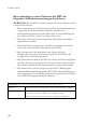
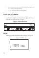
Front and Rear Panels
Four status indicators Link, Activity, Fan, Thermal, and Power indicators
are located on the RPU’s front panel. While the AC supply and DC backup
receptacles are located on the RPU’s rear panel.
Figure 1-1 Front and Rear Panels
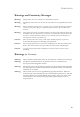
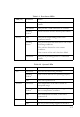
LEDs
The following diagram and tables describe the functions of the LEDs.
Figure 1-2 LEDs
Fan
Thermal Power
Link
Activity
100-240V, 50-60Hz 10A
Fan
Thermal Power
Link
Activity