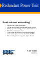
Redundant Power Unit Fault-tolerant networking! • • • • • • • Supports up to four switch units AC line draws power from different supply circuit DC line provides backup power to attached devices Thermal overload protection Over-voltage protection for each output channel Over-current protection can shut down the RPU Short-circuit protection against output channels User Guide SMCRPU14
Redundant Power Unit User Guide Powers up to four SMC networking devices 38 Tesla Irvine, CA 92618 Phone: (949) 679-8000 Janurary 2005 Pub.
Information furnished by SMC Networks, Inc. (SMC) is believed to be accurate and reliable. However, no responsibility is assumed by SMC for its use, nor for any infringements of patents or other rights of third parties which may result from its use. No license is granted by implication or otherwise under any patent or patent rights of SMC. SMC reserves the right to change specifications at any time without notice. Copyright © 2005 by SMC Networks, Inc. 38 Tesla Irvine, CA 92618 All rights reserved.
LIMITED WARRANTY Limited Warranty Statement: SMC Networks, Inc. (“SMC”) warrants its products to be free from defects in workmanship and materials, under normal use and service, for the applicable warranty term. All SMC products carry a standard 90-day limited warranty from the date of purchase from SMC or its Authorized Reseller. SMC may, at its own discretion, repair or replace any product not operating as warranted with a similar or functionally equivalent product, during the applicable warranty term.
LIMITED WARRANTY WARRANTIES EXCLUSIVE: IF AN SMC PRODUCT DOES NOT OPERATE AS WARRANTED ABOVE, CUSTOMER’S SOLE REMEDY SHALL BE REPAIR OR REPLACEMENT OF THE PRODUCT IN QUESTION, AT SMC’S OPTION. THE FOREGOING WARRANTIES AND REMEDIES ARE EXCLUSIVE AND ARE IN LIEU OF ALL OTHER WARRANTIES OR CONDITIONS, EXPRESS OR IMPLIED, EITHER IN FACT OR BY OPERATION OF LAW, STATUTORY OR OTHERWISE, INCLUDING WARRANTIES OR CONDITIONS OF MERCHANTABILITY AND FITNESS FOR A PARTICULAR PURPOSE.
COMPLIANCES COMPLIANCES FCC - Class B This equipment has been tested and found to comply with the limits for a Class B digital device, pursuant to Part 15 of the FCC Rules. These limits are designed to provide reasonable protection against harmful interference in a residential installation. This equipment generates, uses and can radiate radio frequency energy and, if not installed and used in accordance with instructions, may cause harmful interference to radio communications.
COMPLIANCES EC Conformance Declaration - Class B SMC contact for these products in Europe is: SMC Networks Europe, Edificio Conata II, Calle Fructuós Gelabert 6-8, 2o, 4a, 08970 - Sant Joan Despí, Barcelona, Spain.
COMPLIANCES Australia AS/NZS 3548 (1995) - Class B SMC contact for products in Australia is: SMC Communications Pty. Ltd. Suite 18, 12 Tryon Road, Lindfield NSW2070, Phone: 61-2-94160437 Fax: 61-2-94160474 Please read the following safety information carefully before installing the RPU: WARNING: Installation and removal of the unit must be carried out by qualified personnel only.
COMPLIANCES France and Peru only This unit cannot be powered from IT† supplies. If your supplies are of IT type, this unit must be powered by 230 V (2P+T) via an isolation transformer ratio 1:1, with the secondary connection point labelled Neutral, connected directly to earth (ground). † Impédance à la terre Power Cord Set U.S.A. and Canada The cord set must be UL-approved and CSA certified. The minimum specifications for the flexible cord are: - No. 18 AWG - not longer than 2 meters, or 16 AWG.
COMPLIANCES • Vous devez raccorder ce groupe à une sortie mise à la terre (mise à la masse) afin de respecter les normes internationales de sécurité. • Le coupleur d’appareil (le connecteur du groupe et non pas la prise murale) doit respecter une configuration qui permet un branchement sur une entrée d’appareil EN 60320/IEC 320. • La prise secteur doit se trouver à proximité de l’appareil et son accès doit être facile.
COMPLIANCES Bitte unbedingt vor dem Einbauen des RPU die folgenden Sicherheitsanweisungen durchlesen: WARNUNG: Die Installation und der Ausbau des Geräts darf nur durch Fachpersonal erfolgen. • Diese Anleitung ist fr die Benutzung durch Netzwerkadministratoren vorgesehen, die fr die Installation und das einstellen von Netzwerkkomponenten verantwortlich sind; sie setzt Erfahrung bei der Arbeit mit LANs (Local Area Networks) voraus.
COMPLIANCES Warnings and Cautionary Messages Warning: This product does not contain any serviceable user parts. Warning: Installation and removal of the unit must be carried out by qualified personnel only. Warning: When connecting this device to a power outlet, connect the field ground lead on the tri-pole power plug to a valid earth ground line to prevent electrical hazards. Warning: This switch uses lasers to transmit signals over fiber optic cable.
Environmental Statement The manufacturer of this product endeavours to sustain an environmentally-friendly policy throughout the entire production process. This is achieved though the following means: • • • • • • Adherence to national legislation and regulations on environmental production standards. Conservation of operational resources. Waste reduction and safe disposal of all harmful un-recyclable by-products. Recycling of all reusable waste content.
TABLE OF CONTENTS 1 About the Redundant Power Unit . . . . . . . . . . . . . . . .1-1 Overview . . . . . . . . . . . . . . . . . . . . . . . . . . . . . . . . . . . . . . . . . . . . . . . . . . Features and Benefits . . . . . . . . . . . . . . . . . . . . . . . . . . . . . . . . . . . . . . . . Front and Rear Panels . . . . . . . . . . . . . . . . . . . . . . . . . . . . . . . . . . . . . . . LEDs . . . . . . . . . . . . . . . . . . . . . . . . . . . . . . . . . . . . . . . . . . . . . . . . . . . . .
TABLE OF CONTENTS x
CHAPTER 1: ABOUT THE REDUNDANT POWER UNIT Overview This Redundant Power Unit (SMCRPU14) can supply 600 Watts of backup power to four switches in the event of an AC loss or failure of an internal power supply. Features and Benefits • Supports four switch units with 12 VDC supply of up to 150 W. • Indicator LEDs located on the front panel. • RPU AC line cord can draw power from a different supply circuit. • DC line cords provide backup power to attached devices.
• Short-circuit protection prevents the RPU from being damaged from a short circuit on any output channel. • The RPU will operate under a no-load condition. Front and Rear Panels Four status indicators Link, Activity, Fan, Thermal, and Power indicators are located on the RPU’s front panel. While the AC supply and DC backup receptacles are located on the RPU’s rear panel.
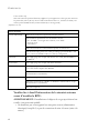
Table 1-1 Port Status LEDs LED (1-4) Condition Status Link Off The port does not have a valid connection to a switch. On Yellow The port has a valid connection to a switch. Flashing Yellow There has been an RPU internal power failure. Off The port is not providing power to the connected switch. Flashing Green The port has been shut down due to one of the following conditions: Activity The unit has detected an over-current condition. One or more of the unit’s fans have failed.
1-4
CHAPTER 2: INSTALLING THE REDUNDANT POWER UNIT Installation The RPU may be placed on a desktop or mounted in a rack. Caution: DO NOT place the RPU on the floor as the case is not waterproof. It is recommended that this RPU be installed in a network equipment rack. Selecting a Site RPU units can be mounted in a standard 19-inch equipment rack or on a flat surface. Be sure to follow the guidelines below when choosing a location.
- Make sure that a separate grounded power outlet that provides 100 to 240 VAC, 50-60 Hz, is within 2 m (6.56 feet) of each device and is powered from an independent circuit breaker. As with any equipment, using a filter or surge suppressor is recommended. Equipment Checklist After unpacking the RPU, check the contents to be sure you have received all the components. Then, before beginning the installation, be sure you have all other necessary installation equipment.
Mounting RPU units can be mounted in a standard 19-inch equipment rack or on a desktop or shelf. Mounting instructions for each type of site follow. Rack Mounting Before rack mounting the unit, pay particular attention to the following factors: • Temperature: Since the temperature within a rack assembly may be higher than the ambient room temperature, check that the rack-environment temperature is within the specified operating temperature range.
To rack-mount devices: 1. Attach the brackets to the device using the screws provided in the Bracket Mounting Kit. Figure 2-1 Attaching the Brackets Li nk Ac tiv ity Fa n Th er m al Po we r 2. Mount the device in the rack, using four rack-mounting screws (not provided). Figure 2-2 Installing the RPU in a Rack Li nk Ac tiv ity Fa n Th er m al Po w er 3. If also installing RPUs, mount them in the rack below the other devices.
Montage (Rack Mounting - German) SMCRPU14 RPU-Einheiten können an ein standardmäßiges 19-Zoll Einrichtungsrack, einen Arbeitstisch oder ein Regal montiert werden. Folgend finden Sie die Montageanweisungen für jeden Positionstyp.
Desktop or Shelf Mounting 1. Attach the four adhesive feet to the bottom of the first RPU unit. Figure 2-3 Attaching the Adhesive Feet 10 0-2 40 V, 50 -60 Hz 10 A 2. Set the device on a flat surface near an AC power source, making sure there are at least five centimeters or two inches of space on all sides for proper air flow. Connecting Switches to the RPU Caution: DO NOT connect the RPU to an AC power source until DC power cords have been connected to the supported switches.
Figure 2-4 Power Receptacle 100-240V, 50-60Hz 10A 2. Connect one end of a DC cord to the redundant power receptacle on the supported switch and the other end to an available receptacle on the RPU. 3. Repeat steps 1 and 2 for connecting up to four supported switches to the RPU. 4. Connect one end of the AC cord to the AC receptacle on the RPU, and the other end to a grounded power outlet. 5. Check the LEDs on the RPU to ensure proper operation. The Link LEDs for connected switches should light up.
Figure 2-5 Connecting the RPU in a Stack Stack RPU input port 100-240V, 50-60Hz 8A RPU Unit RPU output port AC Power Supply No.1 AC Power Supply No.2 Note: For International use, you may need to change the AC line cord. You must use a line cord set that has been approved for the receptacle type in your country.
APPENDIX A TROUBLESHOOTING Diagnosing RPU Indicators Table A-1 Troubleshooting Chart Symptom Action Power LED is Off • Internal power supply is disconnected. • Check connections between the RPU, the power cord, and the wall outlet. • Contact Technical Support. Link LED is Off • The port does not have a valid connection to a switch. • Check connections between the RPU and the switch. • Check that power is being supplied to the RPU.
Table A-1 Troubleshooting Chart Symptom Action Fan LED is Off • The unit is powered off. Thermal LED is Flashing Yellow • Indicates a high temperature that is approaching an over-temperature condition. • Check that the unit's cooling fans are operating normally. • Power off the RPU unit and allow to cool. • If the condition persists, contact Technical Support.
APPENDIX B. SPECIFICATIONS Physical Characteristics Ports 4 RPU DC power outlets (IEC socket 216C743-07) LEDs Port: Link, Activity System: Power, Fan, Thermal Weight 5.5 kg (12.1 lbs) Size 44.0 x 32.3 x 4.3 cm (17.34 x 12.6 x 1.69 in.
Power Supply Internal, auto-ranging transformer: 100 to 240 VAC, 50 to 60 Hz Output 11.5 VDC Power Consumption 644 W (Maximum) 161 W (Maximum per port) Maximum Current 7.8 A @ 110 VAC 3.
Safety CSA/ C US (CSA 60950-00 & UL60950) CB: IEC 60950 EN 60950 (TÜV/GS) B-3
B-4
INDEX A I adhesive feet, attaching 2-6 air flow requirements 2-1 brackets, attaching 2-4 installation desktop or shelf mounting 2-6 power requirements 2-2 problems A-2 rack mounting 2-3 site requirements 2-1 C L CE Mark 0-iv compliances 0-iii EMC B-2 safety B-3 contents of package 2-2 cooling problems A-2 cord sets, international 2-8 LED indicators problems A-1 location requirements 2-1 B D M mounting the RPU in a rack 2-3 on a desktop or shelf 2-6 desktop mounting 2-6 P E package contents 2-
INDEX specifications compliances B-2 environmental B-1 physical B-1 power B-2 standards compliance B-2 IEEE B-2 standards compliance 0-iii surge suppressor, using 2-2 T temperature within a rack 2-3 troubleshooting in-band access A-2 power and cooling problems A-2 RPU indicators A-1 INDEX-2
FOR TECHNICAL SUPPORT, CALL: From U.S.A. and Canada (24 hours a day, 7 days a week) (800) SMC-4-YOU; (949) 679-8000; Fax: (949) 679-1481 From Europe (8:00 AM - 5:30 PM UK Time) 44 (0) 118 974 8700; Fax: 44 (0) 118 974 8701 INTERNET E-mail addresses: techsupport@smc.com european.techsupport@smc-europe.com Driver updates: http://www.smc.com/index.cfm?action=tech support drivers downloads World Wide Web: http://www.smc.com/ http://www.smc-europe.com/ FOR LITERATURE OR ADVERTISING RESPONSE, CALL: U.S.A.