EZ Switch 10/100/1000 Web-Managed Smart Switch ◆ ◆ ◆ ◆ ◆ ◆ ◆ ◆ User friendly web management interface Supports Qos, VLANs and Trunk configuration Automatic MDI/MDI-X operation Store-and-forward switching ensures error-free transmission Half- and full-duplex flow control prevents packets from being dropped under heavy loading Plug-and-play—Optional configuration using web interface “At-a-glance” LEDs for port and system status monitoring Desktop or rack installation Management Guide SMCGS16-Smart SMCGS24-
EZ Switch 10/100/1000 Management Guide From SMC’s EZ line of low-cost workgroup LAN solutions 38 Tesla Irvine, CA 92618 Phone: (949) 679-8000 August 2005 Pub.
Information furnished by SMC Networks, Inc. (SMC) is believed to be accurate and reliable. However, no responsibility is assumed by SMC for its use, nor for any infringements of patents or other rights of third parties which may result from its use. No license is granted by implication or otherwise under any patent or patent rights of SMC. SMC reserves the right to change specifications at any time without notice. Copyright © 2005 by SMC Networks, Inc. 38 Tesla Irvine, CA 92618 All rights reserved.
LIMITED WARRANTY Limited Warranty Statement: SMC Networks, Inc. (“SMC”) warrants its products to be free from defects in workmanship and materials, under normal use and service, for the applicable warranty term. All SMC products carry a standard 90-day limited warranty from the date of purchase from SMC or its Authorized Reseller. SMC may, at its own discretion, repair or replace any product not operating as warranted with a similar or functionally equivalent product, during the applicable warranty term.
WARRANTIES EXCLUSIVE: IF AN SMC PRODUCT DOES NOT OPERATE AS WARRANTED ABOVE, CUSTOMER’S SOLE REMEDY SHALL BE REPAIR OR REPLACEMENT OF THE PRODUCT IN QUESTION, AT SMC’S OPTION. THE FOREGOING WARRANTIES AND REMEDIES ARE EXCLUSIVE AND ARE IN LIEU OF ALL OTHER WARRANTIES OR CONDITIONS, EXPRESS OR IMPLIED, EITHER IN FACT OR BY OPERATION OF LAW, STATUTORY OR OTHERWISE, INCLUDING WARRANTIES OR CONDITIONS OF MERCHANTABILITY AND FITNESS FOR A PARTICULAR PURPOSE.
COMPLIANCES COMPLIANCES FCC - Class A This equipment has been tested and found to comply with the limits for a Class A digital device, pursuant to Part 15 of the FCC Rules. These limits are designed to provide reasonable protection against harmful interference in a residential installation. This equipment generates, uses and can radiate radio frequency energy and, if not installed and used in accordance with instructions, may cause harmful interference to radio communications.
COMPLIANCES • Electrostatic Discharge according to EN 61000-4-2:1995 (Contact Discharge: ±4 kV, Air Discharge: ±8 kV) • Radio-frequency electromagnetic field according to EN 61000-4-3:1996 (80 - 1000 MHz with 1 kHz AM 80% Modulation: 3 V/m) • Electrical fast transient/burst according to EN 61000-4-4:1995 (AC/DC power supply: ±1 kV, Data/Signal lines: ±0.
COMPLIANCES Please read the following safety information carefully before installing the Switch: WARNING: Installation and removal of the unit must be carried out by qualified personnel only. • This guide is intended for use by network administrators who are responsible for setting up and installing network equipment; consequently it assumes a basic working knowledge of LANs (Local Area Networks). • The unit must be connected to an earthed (grounded) outlet to comply with international safety standards.
COMPLIANCES France and Peru only This unit cannot be powered from IT† supplies. If your supplies are of IT type, this unit must be powered by 230 V (2P+T) via an isolation transformer ratio 1:1, with the secondary connection point labelled Neutral, connected directly to earth (ground). † Impédance à la terre Power Cord Set U.S.A. and Canada The cord set must be UL-approved and CSA certified. The minimum specifications for the flexible cord are: - No. 18 AWG - not longer than 2 meters, or 16 AWG.
COMPLIANCES • Vous devez raccorder ce groupe à une sortie mise à la terre (mise à la masse) afin de respecter les normes internationales de sécurité. • Le coupleur d’appareil (le connecteur du groupe et non pas la prise murale) doit respecter une configuration qui permet un branchement sur une entrée d’appareil EN 60320/IEC 320. • La prise secteur doit se trouver à proximité de l’appareil et son accès doit être facile.
COMPLIANCES Cordon électrique - Il doit être agréé dans le pays d’utilisation Suisse: La prise mâle d’alimentation doit respecter la norme SEV/ASE 1011. Europe La prise secteur doit être conforme aux normes CEE 7/7 (“SCHUKO”) LE cordon secteur doit porter la mention ou et doit être de type HO3VVF3GO.75 (minimum). Bitte unbedingt vor dem Einbauen des RPU die folgenden Sicherheitsanweisungen durchlesen: WARNUNG: Die Installation und der Ausbau des Geräts darf nur durch Fachpersonal erfolgen.
COMPLIANCES Stromkabel. Dies muss von dem Land, in dem es benutzt wird geprüft werden: Schweiz Dieser Stromstecker muß die SEV/ASE 1011Bestimmungen einhalten. Europe Das Netzkabel muß vom Typ HO3VVF3GO.75 (Mindestanforderung) sein und die Aufschrift oder tragen. Der Netzstecker muß die Norm CEE 7/7 erfüllen (”SCHUKO”). Warnings and Cautionary Messages Warning: This product does not contain any serviceable user parts.
COMPLIANCES Environmental Statement The manufacturer of this product endeavours to sustain an environmentally-friendly policy throughout the entire production process. This is achieved though the following means: • • • • • • Adherence to national legislation and regulations on environmental production standards. Conservation of operational resources. Waste reduction and safe disposal of all harmful un-recyclable by-products. Recycling of all reusable waste content.
TABLE OF CONTENTS Introduction . . . . . . . . . . . . . . . . . . . . . . . . . . . . . . . . . . . 1 Features and Benefits . . . . . . . . . . . . . . . . . . . . . . . . . . . . . . . . . . . . . . . . . . 1 Initial Configuration . . . . . . . . . . . . . . . . . . . . . . . . . . . . 2 Configuring the Switch . . . . . . . . . . . . . . . . . . . . . . . . . . 4 Using the Web Interface . . . . . . . . . . . . . . . . . . . . . . . . . . . . . . . . . . . . . . . 4 Navigating the Web Browser Interface .
Product Specifications . . . . . . . . . . . . . . . . . . . . . . . . . .37 EZ Switch 10/100/1000 . . . . . . . . . . . . . . . . . . . . . . . . . . . . . . . . . . . . . .
FEATURES AND BENEFITS INTRODUCTION The EZ Switch 10/100/1000, SMCGS16-Smart and SMCGS24-Smart, are high performance web managed smart switches for delivering performance and control to your network. They provide 16/24 full-duplex 1000BASE-T ports that significantly improve network performance and boost throughput using Smart features configured on the web interface. With 32/48 Gigabits of throughput bandwidth, these switches provide the quickest solution to meeting the growing demands on your network.
INITIAL CONFIGURATION INITIAL CONFIGURATION To make use of the management features of your SMC Smart Switch you must first give it an IP address. For simplicity, this should be done before you permanently install the switch in the network. The following procedure is recommended: 1. Place your Smart Switch close to the PC that you will use to configure it. It will help if you can see the front panel of the switch while working on your PC. 2.
FEATURES AND BENEFITS 6. Click on the SYSTEM menu-choice then click on LAN Settings when it appears. On the LAN Settings page, enter the IP address, Subnet Mask and Gateway IP Address for the switch then click on the APPLY button. No other configuration changes are required at this stage but it is recommended that you change the administrator’s password before logging out.
CONFIGURING THE SWITCH CONFIGURING THE SWITCH Using the Web Interface This switch provides an embedded HTTP web agent. Using a web browser you can configure the switch and view statistics to monitor network activity. The web agent can be accessed by any computer on the network using a standard web browser (Internet Explorer 5.5 or above, or Mozilla Firefox 1.0 or above). Prior to accessing the switch from a web browser, be sure you have first performed the following tasks: 1.
NAVIGATING THE WEB BROWSER INTERFACE Navigating the Web Browser Interface To access the web-browser interface you must first enter a password. The user has Read/Write access to all configuration parameters and statistics. The default password for the switch is “smcadmin.” If user input is not detected within five minutes, the current session will be terminated. Home Page When your web browser connects with the switch’s web agent, the home page is displayed as shown below.
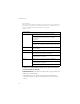
CONFIGURING THE SWITCH Configuration Options Configurable parameters have a dialog box or a drop-down list. Once a configuration change has been made on a page, be sure to click on the Apply button to confirm the new setting. The following table summarizes the web page configuration buttons. Table 2 Web Page Configuration Buttons Button Action Apply Sets specified values to the system. Cancel Discards all changes and restores current values. Help Links directly to web help.
NAVIGATING THE WEB BROWSER INTERFACE Main Menu Using the onboard web agent, you can define system parameters, manage and control the switch, and all its ports, or monitor network conditions. The following table briefly describes the selections available from this program. Table 2-1 Switch Main Menu Menu Description STATUS Page 6 Overview Provides basic system description, including system information, address information, port information, trunk information, and VLAN information.
CONFIGURING THE SWITCH Table 2-1 Switch Main Menu (Continued) Menu Description Page Broadcast Control Sets the broadcast storm control parameters for every port on the Switch. 21 Port Mirroring Sets up the port mirroring features of the switch to enable traffic monitoring. 22 TRUNKS 23 Membership Specifies ports to group into static trunks Settings Configures trunk connection settings 24 Rate Limiting Sets the rate limiting parameters for each Trunk configured on the Switch.
WEB CONFIGURATION Address Information • Management VLAN – ID of the configured VLAN (this is set to 1 and cannot be changed) all ports on the unit are members of VLAN 1. The management station must always be attached to a port on VLAN 1. • IP Address – Address of the VLAN to which the management station is attached. (Note that the management station must always be on VLAN 1) Valid IP addresses consist of four numbers, 0 to 255, separated by periods.
CONFIGURING THE SWITCH trunk. This is a number, the speed in Mbps, followed by either “Full” for full-duplex or “Half” for half-duplex. This can be changed on the TRUNKS > Settings page. • Ports – The ports that are members of the trunk. VLAN Inoformation • VLAN ID – A number in the range 1 - 4094 which identifies the VLAN. • VLAN Member – A list of the ports that are members of the VLAN. By default, all ports are members of VLAN 1.
WEB CONFIGURATION Web – Click STATUS, Overview.
CONFIGURING THE SWITCH Showing Port Statistics You can display statistics on network traffic from the ports. These statistics can be used to identify potential problems with the switch (such as a faulty port or unusually heavy loading). All values displayed have been accumulated since the last system reboot, but can be reset to zero by clicking the CLEAR button. The current statistics are not displayed until you click the REFRESH button.
WEB CONFIGURATION Table 4 Port Statistics (Continued) Parameter Description Received Broadcast Packets The number of packets, delivered by this sub-layer to a higher (sub-)layer, which were addressed to a broadcast address at this sub-layer. Transmitted Octets The total number of octets transmitted out of the interface, including framing characters.
CONFIGURING THE SWITCH Table 4 Port Statistics (Continued) 14 Parameter Description Received Bytes Total number of bytes of data received on the network. This statistic can be used as a reasonable indication of Ethernet utilization. Broadcast Frames The total number of good frames received that were directed to the broadcast address. Note that this does not include multicast packets. CRC/Alignment Errors The number of CRC/alignment errors (FCS or alignment errors).
WEB CONFIGURATION Web – Click STATUS, Statistics. Figure 5 Port Statistics Displaying System Name You can easily identify the system by displaying the device name. Field Attributes • Switch Name – Name assigned to the switch system.
CONFIGURING THE SWITCH Web – Click System, Name. Figure 6 System Name Setting the Switch’s IP Address This section describes how to configure an IP interface for management access over the network. The IP address for this switch is 192.168.2.10 by default. To manually configure an address, you need to change the switch’s default settings (IP address 192.168.2.10 and netmask 255.255.255.0) to values that are compatible with your network.
WEB CONFIGURATION Manual Configuration Web – Click System, LAN Settings. Enter the IP address, subnet mask and gateway, then click APPLY. Figure 7 LAN Settings Configuring the Logon Password The administrator has write access for all parameters governing the onboard agent. You should therefore assign a new administrator password as soon as possible, and store it in a safe place. Field Attributes • Password – Specifies the user password.
CONFIGURING THE SWITCH Web – Click System, Password. To change the password for the administrator, enter current password, the new password, confirm it by entering it again, then click APPLY. Figure 8 Password Settings Tools On Tools page, you can restore the switch to default settings, upgrade the firmware of the switch, or restart the switch. Restore to Factory Defaults Force the Switch to restore the original factory settings.
WEB CONFIGURATION Web – Click System, Tools, Reset to Factory Defaults. Figure 9 Reset to Factory Defaults Upgrade Firmware Upgrades the Switch system firmware using a file provided by SMC. Select "Upgrade Firmware" from the Tools drop-down list then click on the "Browse" button to select the firmware file. Finally, press the APPLY button to upgrade the selected Switch firmware file. You can download firmware files for your Switch from the Support section of www.smc.com.
CONFIGURING THE SWITCH Figure 11 Restart Switch Register Product Register your product if you have not already done so. Web – Click System, Register Product. By clicking the Register Now button you will be taken to the SMC website, where you can enter the products details. Figure 12 Register Product Port Configuration You can use the Port Configuration page to manually fix the speed, duplex mode, and flow control.
WEB CONFIGURATION • Trunk – Indicates if a port is a member of a trunk. Web – Click PORTS, Settings. Figure 13 Port Configuration Configuring Rate Limits This function allows the network manager to control the maximum rate for traffic transmitted or received on an interface. Rate limiting is configured on interfaces at the edge of a network to limit traffic into or out of the switch.
CONFIGURING THE SWITCH The Input/Output Bandwidth Limit field is a type-in box which accepts an integer number in the range 1 to 100. The number specifies the percentage of the total input bandwidth of the port that can be used before packets are dropped or flow-control starts. Web – Click PORTS, Rate Limiting. This page enables you to set the rate limiting parameters for each port on the Switch.
WEB CONFIGURATION Port Broadcast Control Broadcast storms may occur when a device on your network is malfunctioning, or if application programs are not well designed or properly configured. If there is too much broadcast traffic on your network, performance can be severely degraded or everything can come to complete halt. You can protect your network from broadcast storms by setting a threshold for broadcast traffic for each port. Any broadcast packets exceeding the specified threshold will then be dropped.
CONFIGURING THE SWITCH Port Mirroring You can mirror traffic from any source port to a target port for real-time analysis. You can then attach a logic analyzer or RMON probe to the target port and study the traffic crossing the source port in a completely unobtrusive manner. Field Attributes Ports to Mirror Select the ports that you want to mirror from this section of the page. A port will be mirrored when the"Mirroring Enabled" check-box is checked.
WEB CONFIGURATION Web – Click PORTS, Port Mirroring. Figure 16 Port Mirroring Trunks Membership This page allows you to create a maximum of eight trunks of up to eight ports each. The Membership Table has one row for each port and ten columns. Each row contains nine radio buttons which are used to indicate which trunk (if any) the port belongs to. Field Attributes • Port – The front-panel port-number of the port.
CONFIGURING THE SWITCH Web – Click TRUNKS, Membership. Click to select which Trunk member to which each port belongs. Figure 17 Trunk Membership Trunk Configuration Field Attributes • Trunk – Indicates trunk identification. • Speed/Duplex – Allows you to manually set the port speed and duplex mode for all ports in the trunk. • Flow Control – Allows flow control to be enabled or disabled. When the box is checked, flow control is enabled. • Ports – Indicates which ports belong to the trunk.
WEB CONFIGURATION Web – Click TRUNKS, Settings. Figure 18 Trunk Configuration Trunk Rate Limit This page allows you to change the maximum data-rate into and out of each trunk on the switch. Field Attributes • Trunk – Indicates trunk identification. • Trunk Speed – Indicates the trunk speed. • Enable Input Rate Limiting - Click to select the box to enable the Input Rate Limiting function. • Input Limit – Enter the desired limit.
CONFIGURING THE SWITCH Web – Click TRUNKS, Settings. Figure 19 Trunk Rate Limiting VLAN Settings You can configure VLAN behavior for specific interfaces, including the default VLAN identifier (PVID) and accepted frame types. This page allows you to create and delete VLANs (Virtual LANs) and to change the VLAN membership and behaviour of individual ports. VLANs are powerful but can be difficult to set up properly.
WEB CONFIGURATION • All ports can send and receive both VLAN-tagged and untagged packets (i.e. they are hybrid ports) In the default configuration, any port is able to send traffic to any other port and a PC connected to any port will be able ro reach the management interface. Broadcast traffic, for example, will be flooded to all ports on the switch. There are three different parameters that can be configured for each port on the switch; VLAN IDs (VLAN membership), PVID and Packet Type.
CONFIGURING THE SWITCH tagged or untagged frames, or only tagged frames. When set to receive all frame types, any received frames that are untagged are assigned to the default VLAN. PCs should be connected to ports with Packet Type set to “All”. PCs cannot, in general, send or receive tagged packets. Switches should be connected to each other with Packet Type set to “Tagged”. If the Packet Type is set to “All”, the port can accept incoming tagged and untagged packets.
WEB CONFIGURATION QOS Settings QoS (Quality of Service) is a mechanism which is used to prioritize certain traffic as it is moves through the switch. Traffic can be classified as High or Normal priority and, when the switch is heavily loaded, it is the Normal priority packets that are dropped first. You can select how traffic is prioritized by using one of the four QoS modes which is selected using the QoS Mode drop-down list. Note: Only one QoS mode can be active at one time.
CONFIGURING THE SWITCH table appears and you are able to select up to ten IP Ports for prioritization. Prioritized port numbers can be in the range 0 - 65535 inclusive. The specified ports will be given either normal or high priority depending on the value selected in the Priority drop-down list. If the specified port numbers are given high priority, all other port numbers will have normal priority.
WEB CONFIGURATION Web – Click QOS, Settings. In QoS Mode, select QoS Diabled, 802.1p, IP Port, or DSCP to configure the related parameters.
TROUBLESHOOTING TROUBLESHOOTING Diagnosing Switch Indicators 1. Symptom Power LED does not light after power on. Probable Causes • AC power cord may be defective. Possible Solutions • Check for loose connections. • Check the power outlet by using it for another device. • Replace the AC power cord. 2. Symptom Link LED does not light after connection is made. Probable Causes • Switch port, network card or cable may be defective.
DIAGNOSING SWITCH INDICATORS 3. Forgotten password If you have forgotten the administration password you can return the Switch to its factory default state by dong the following: 1. Remove the power cord from the back of the Switch. 2. Remove all cables from the front-panel ports. 3. Connect port 1 to port 2, on the front panel, using a standard network cable. 4. Reconnect the power cord to the rear of the Switch. 5. Wait at least 40 seconds before disconnecting port 1 from port 2.
CHANGING PC’S IP ADDRESS CHANGING PC’S IP ADDRESS To change the IP address of your PC: 1. On Windows, go to Start, Settings, Network and Dial-up Connections. 2. Right-click the connectin icon of which the IP address you want to change, and then click properties. 3. In General tab, under Components checked are used by this connection, click to select Internet Protocol (TCP/IP), and then click Properties to open Internet Protocol (TCP/IP) Properties dialog box. 4.
EZ SWITCH 10/100/1000 PRODUCT SPECIFICATIONS EZ Switch 10/100/1000 Standards Conformance IEEE 802.
PRODUCT SPECIFICATIONS Weight SMCGS16-Smart: 2.0 kg (4.04 lbs) SMCGS24-Smart: 2.2 kg (4.85 lbs) MAC Address Table 8 K entries Memory Buffer SMCGS16-Smart: 272 Kbits on-chip frame buffer SMCGS24-Smart: 400 Kbits on-chip frame buffer Power Consumption SMCGS16-Smart: 15.8 Watts SMCGS24-Smart: 24.
FOR TECHNICAL SUPPORT, CALL: From U.S.A. and Canada (24 hours a day, 7 days a week) (800) SMC-4-YOU; Phn: (949) 679-8000; Fax: (949) 679-1481 From Europe: Contact details can be found on www.smc.com INTERNET E-mail addresses: techsupport@smc.com Driver updates: http://www.smc.com/index.cfm?action=tech support drivers downloads World Wide Web: http://www.smc.com/ FOR LITERATURE OR ADVERTISING RESPONSE, CALL: U.S.A.