
User's Manual


– 15 –
2 HARDWARE DESCRIPTION
This chapter describes the front panel, rear panel and LED indicators of the
switch. The SMCGS1601 and SMCGS2401 only differ in the number of ports, and
all figures in this guide are of the SMCGS2401.
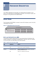
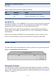
FRONT PANEL
The front panel of SMCGS2401 consists of switch LED indicators, and 24 10/100/
1000 Mbps RJ-45 ports.
Figure 2: SMCGS2401 Switch Front Panel
PORT AND SYSTEM STATUS LEDS
The switches include a display panel for key system and port indications that
simplify installation and network troubleshooting. The LEDs, which are located
on the front panel, are described in the following table.
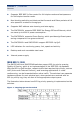
Table 1: System and Port Status LEDs
LED Condition Status
POWER On Green The internal power supply is operating normally.
Off The unit has no power connected.
Link/Act On/Flashing Green Port has established a valid network connection.
Flashing indicates activity.
Off There is no valid link on the port.