USER GUIDE EZ SwitchTM 10/100 24-Port 10/100Mbps + 2G Combo Unmanaged PoE Switch SMCFS2601P
EZ SwitchTM 10/100 User Guide From SMC’s EZ line of low-cost workgroup LAN solutions No. 1, Creation Road III, Hsinchu Science Park, 30077, Taiwan, R.O.C.
Information furnished by SMC Networks, Inc. (SMC) is believed to be accurate and reliable. However, no responsibility is assumed by SMC for its use, nor for any infringements of patents or other rights of third parties which may result from its use. No license is granted by implication or otherwise under any patent or patent rights of SMC. SMC reserves the right to change specifications at any time without notice. Copyright © 2013 by SMC Networks, Inc. No.
WARRANTY AND PRODUCT REGISTRATION To register SMC products and to review the detailed warranty statement, please refer to the Support Section of the SMC Website at http://www.smc.com.
COMPLIANCES AND SAFETY STATEMENTS FCC - CLASS A This equipment has been tested and found to comply with the limits for a Class A digital device, pursuant to part 15 of the FCC Rules. These limits are designed to provide reasonable protection against harmful interference when the equipment is operated in a commercial environment.
ABOUT THIS GUIDE PURPOSE This guide details the hardware features of the switch, including the physical and performance-related characteristics, and how to install the switch. AUDIENCE The guide is intended for use by network administrators who are responsible for installing and setting up network equipment; consequently, it assumes a basic working knowledge of LANs (Local Area Networks).
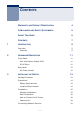
CONTENTS 1 WARRANTY AND PRODUCT REGISTRATION 4 COMPLIANCES AND SAFETY STATEMENTS 5 ABOUT THIS GUIDE 6 CONTENTS 7 INTRODUCTION 9 Overview 9 Features 2 9 HARDWARE DESCRIPTION 11 Front Panel 11 Port and System Status LEDs RJ-45 Ports 12 Rear Panel 12 AC Power Socket 3 11 12 INSTALLING THE SWITCH 13 Package Contents 13 Precautions 14 Safety Requirements 14 Location Requirements 14 Installation 15 Desktop Installation 15 Rack Installation 16 How to Connect to AC Power
CONTENTS 4 A Cabling Guidelines 19 Connecting to PCs, Servers, Hubs and Switches 19 PRODUCT APPLICATION 20 Department/Workgroup PoE Switch 20 Power over Ethernet Powered Devices 21 TROUBLESHOOTING 22 Diagnosing Switch Indicators 22 The Power LED is Off 22 The Link/Act LED is Off when a Device is Connected to the Corresponding Port 22 B Power and Cooling Problems 22 Installation 23 SPECIFICATIONS 24 Physical Characteristics 24 – 8 –
1 INTRODUCTION OVERVIEW SMC Network’s SMCFS2601P 24-Port 10/100 +2G Combo Unmanaged PoE Switch provides seamless network connections, integrating 1000 Mbps Gigabit Ethernet, 100 Mbps Fast Ethernet, and 10 Mbps Ethernet network capabilities. The PoE ports can automatically detect and supply power to IEEE 802.3af/atcompliant Powered Devices (PDs).
CHAPTER 1 | Introduction Overview POE FEATURES The SMCFS2610P can provide up to 30 Watts of power to attached devices, such as VoIP phones, wireless access points, surveillance cameras etc, all over existing Cat.5 cables. The switch can deliver up to 30 Watts on 6 ports, or 15.4 Watts on 12 ports. This eliminates the need for individual power sources for devices in the network, saving on costs for power cables and avoiding power outlet availability issues.
2 HARDWARE DESCRIPTION This chapter describes the front panel, rear panel, and LED indicators of the switch. FRONT PANEL The front panel of the SMCFS2601P consists of switch LED indicators, 24 10/100 Mbps ports, and two 10/100/1000 combo ports. Figure 1: SMCFS2601P Switch Front Panel PORT AND SYSTEM STATUS LEDS The switch includes a display panel for key system and port indications that simplifies installation and network troubleshooting.
CHAPTER 2 | Hardware Description Rear Panel Table 1: System and Port Status LEDs (Continued) LED Condition Status PoE In Use On Green A PoE device is connected. Off No PoE device connected. RJ-45 PORTS The switch contains 24 100BASE-TX and 2 1000BASE-T RJ-45 ports. All ports support automatic MDI/MDI-X operation, so you can use straight-through cables for all network connections to PCs or servers, or to other switches or hubs.
3 INSTALLING THE SWITCH Before installing the switch, verify that you have all the items listed under “Package Contents.” If any of the items are missing or damaged, contact your local SMC distributor. Also be sure you have all the necessary tools and cabling before installing the switch.
CHAPTER 3 | Installing the Switch Precautions PRECAUTIONS To ensure a long-term and stable performance of the switch, pay attention to the following before installation. SAFETY REQUIREMENTS ◆ Before cleaning the switch, disconnect the power supply. Do not clean the switch using a wet cloth, and never use any other liquid for cleaning. ◆ Take waterproof measures during storage, transportation and operation of the equipment. ◆ Use only the power cord provided with the switch.
CHAPTER 3 | Installing the Switch Installation ◆ Position the switch away from water and moisture sources, be sure to provide an acceptable temperature and humidity operating environment. INSTALLATION This switch can be either installed in a standard 19-inch mountable rack or located on a desktop. CAUTION: Please unplug the power cord before installing or removing the switch. DESKTOP INSTALLATION To install the switch on the desktop, follow these steps: 1.
CHAPTER 3 | Installing the Switch Installation Figure 3: Attaching Rubber Feet 4. Upturn the switch and set in the desired location, making sure there is enough ventilation space on all sides for proper airflow. 5. Connect the switch to a power source with the provided power cord. See “How to Connect to AC Power” on page 18. CAUTION: Avoid placing anything heavy on the switch. RACK INSTALLATION To install the switch in an EIA standard-sized, 19-inch rack, follow the instructions described below: 1.
CHAPTER 3 | Installing the Switch Installation Figure 4: Attaching Brackets 2. Use suitable screws (not provided) to secure the brackets to the rack, as illustrated in the following figure. Figure 5: Mounting the Switch 3. Connect the switch to a power source with the provided power cord. See “How to Connect to AC Power” on page 18.
CHAPTER 3 | Installing the Switch Installation HOW TO CONNECT TO AC POWER To supply AC power to the switch, first verify that the external AC power supply can provide 100 to 240 VAC, 50-60 Hz, 0.5 A minimum. To connect the switch to a power source: 1. Plug the power cord into a grounded, 3-pin, AC power source. Figure 6: AC Power Cord and Power Socket 2. Insert the plug on the other end of the power cord directly into the AC input socket on the back of the switch.
CHAPTER 3 | Installing the Switch Connecting Network Devices POWERING ON The SMCFS2601P switch is powered by connecting to an AC power supply using a power cord. When powering on the switch, it automatically initializes and the LED indicators respond as follows: 1. All of the LED indicators flash momentarily for one second, which represents a resetting of the system. 2. The Power LED indicator turns on green.
4 PRODUCT APPLICATION DEPARTMENT/WORKGROUP POE SWITCH The SMCFS2601P provides 24 PoE port interfaces and can build a centrallycontrolled IP phone system, IP camera system, or wireless AP group for the enterprise. Cameras can be installed around the company or campus for surveillance needs, or wireless APs can build a wireless roaming environment in the office. Without being limited by power-socket availability, the switch makes installation of cameras or wireless APs easy and efficient.
CHAPTER 4 | Product Application Power over Ethernet Powered Devices POWER OVER ETHERNET POWERED DEVICES Table 2: Power over Ethernet Powered Devices Voice over IP phones 3~5 Watts Enterprises can install PoE VoIP phones, ATA and other Ethernet/ non-Ethernet end-devices connected to a central location where an un-interruptible power supply and power control system are installed.
A TROUBLESHOOTING DIAGNOSING SWITCH INDICATORS THE POWER LED IS OFF ◆ Make sure the AC power cord is connected to the switch and power source properly. ◆ Make sure the power source is ON. THE LINK/ACT LED IS OFF WHEN A DEVICE IS CONNECTED TO THE CORRESPONDING PORT ◆ Make sure that the cable connectors are firmly plugged into the switch and the device. ◆ Make sure the connected device is turned on and working properly. ◆ The cable must be less than 100 meters long (328 feet).
APPENDIX A | Troubleshooting Installation INSTALLATION Verify that all system components have been properly installed. If one or more components appear to be malfunctioning (such as the power cord or network cabling), test them in an alternate environment where you are sure that all the other components are functioning properly.
B SPECIFICATIONS PHYSICAL CHARACTERISTICS STANDARDS IEEE 802.3 10BASE-T IEEE 802.3u 100BASE-TX IEEE 802.
APPENDIX B | Specifications Physical Characteristics NUMBER OF PORTS 24 10/100 Mbps auto-negotation RJ-45 ports 2 10/100/1000 Mbps combo (RJ-45+SFP) port LED INDICATORS POWER, LNK/Act, PoE in Use, 1000 Mbps TRANSFER METHOD Store-and-Forward MAC ADDRESS LEARNING Automatically learning, automatically aging FRAME FILTER RATE 10BASE-T: 14881 pps/port 100BASE-TX: 148810 pps/port 1000BASE-T: 1488095 pps/port FRAME FORWARD RATE 10BASE-T: 14881 pps/port 100BASE-TX: 148810 pps/port 1000BASE-T: 1488100 pps/por
APPENDIX B | Specifications Physical Characteristics POWER ADAPTER AC INPUT :100V~240V 50/60Hz DC OUTPUT:DC 51V 4.7A DIMENSIONS 440 x 208 x 44 mm (17.3 x 8.1 x 1.77 in.) WEIGHT 2.70 kg (5.95 lbs) FEATURE IEEE 802.3x Flow Control Auto MDI/MDI-X Supports auto-negotiation of speed (10/100 Mbps) and duplex mode (half/full) Wire-speed packet filtering and forwarding rate Store-and-forward architecture filters fragment & CRC error packets Support IEEE 802.3af/802.
APPENDIX B | Specifications Physical Characteristics IMMUNITY EN55024 IEC61000-4/2/3/4/5/6/8/11 EMISSIONS FCC Class A, EN55022/EN61000-3-2/3 SAFETY LVD (EN60950) – 27 –
Headquarters No. 1, Creation Rd. III Hsinchu Science Park Taiwan 30077 Tel: +886 3 563 8888 Fax: +886 3 668 6111 Singapore 15 Enggor Street #10-04, Realty Centre Singapore 079716 Tel: +65-63387667 Fax: +65-63387767 su www.smc.com www.smc-asis.com www.smcnetworks.co.kr Declaration of Conformity (DoC) can be obtained from www.smc.com -> support -> download SMCFS2601P www.smc.com 150200062800A R02 20 Mason • Irvine, CA 92618 • Phn: 949-679-8000 • www.smc.