
Modem User Manual


12
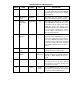
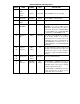
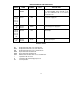
DESCRIPTION OF PIN FUNCTIONS
PIN NO. NAME SYMBOL TYPE DESCRIPTION
nIOIS16 PCMCIA - Active low output asserted
whenever the SMC91C95 is in 16 bit mode,
and “Enable Function” bit in the ECOR
register is high, nREG is low and A4-A15
decode to the LAN address specified in I/O
Base Registers 0 and 1 in PCMCIA attribute
space.
88 nI/O Read nIORD IS with
pullup
Input. Active low read strobe used to access
the SMC91C95 IO space.
87 nI/O Write nIOWR IS with
pullup
Input. Active low write strobe used to access
the SMC91C95 IO space.
86 nMemory
Read
nMEMR IS with
pullup
ISA - Active low signal used by the host
processor to read from the external ROM.
nOutput
Enable
nOE PCMCIA - Output Enable input used to read
from the COR, CSR and attribute memory.
24 nModem
Reset
nMRESET O4 Reset output to Modem. Asserted whenever
RESET pin is high, internal POR is active, or
SRESET bit is high (MCOR bit 7).
18 Modem
Interrupt
MINT I with pull
down
Interrupt input from Modem. Reflected in
INTR (CSR bit 1) and asserts the appropriate
interrupt pin if enabled.
23 nModem
Chip Select
nMCS O4 Chip select output to modem.
17 Modem
Ready
MRDY I with pullup Modem ready input. Low indicates the modem
is not ready, either after reset or exiting from
stop or sleep modes.
27 nModem
Powerdown
nMPWDN O4 Powerdown output to modem controller. This
pin is active (low) when either the PWRDWN
bit (CSR bit 2) is set or the modem is disabled
(not configured).