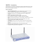
EZ Connect™ Wireless Cable Modem Gateway Install Guide SMC8014W-G
Copyright Information furnished by SMC Networks, Inc. (SMC) is believed to be accurate and reliable. However, no responsibility is assumed by SMC for its use, nor for any infringements of patents or other rights of third parties which may result from its use. No license is granted by implication or otherwise under any patent or patent rights of SMC. SMC reserves the right to change specifications at any time without notice. Copyright © 2006 by SMC Networks, Inc.
TABLE OF CONTENTS CHAPTER 1 | Introduction Features and Benefits Package Contents Minimum Requirements CHAPTER 2 | Getting to know the EZ Connect™ Wireless Cable Modem Gateway LED Indicators Rear Panel Description Resetting and Restoring the EZ Connect™ Wireless Cable Modem Gateway CHAPTER 3 | Installation Basic Installation Procedure CHAPTER 4 | Configuring your Computer Configuring Windows 95/98/Me Configuring Windows 2000 Configuring Windows XP Configuring a Macintosh Computer CHAPTER 5 | Configuring the
CHAPTER 1 | Introduction Congratulations on your purchase of the EZ Connect™ Wireless Cable Modem Gateway. SMC is proud to provide you with a powerful yet simple communication device for connecting your local area network (LAN) to the Internet. Features and Benefits • • • • • • • • • • • • • • EZ 3-Click Installation Wizard - A new and improved way to install your Gateway Modem. In 3 simple clicks, you will be connected to the Internet.
Package Contents Before installing the EZ Connect™ Wireless Cable Modem Gateway, verify that you have the items listed under below. Also be sure that you have the necessary cabling. If any of the items are missing or damaged, contact your local SMC distributor. • • • • • 1 - EZ Connect™ Wireless Cable Modem Gateway 1 - Power adapter (12V/1.
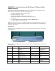
CHAPTER 2 | Getting to Know the EZ Connect™ Wireless Cable Modem Gateway The EZ Connect™ Wireless Cable Modem Gateway is the perfect all in one solution, for the home or business environment. This full-featured device has: • • • • • • • An approved DOCSIS 1.1 and 2.0 Cable modem Advanced SPI Firewall Gateway High-speed 54 Mbps 802.11g Wireless Access Point Comprehensive LEDs for network status and troubleshooting Reset Button 4 – 10/100 Mbps Auto-Sensing LAN ports with Auto-MDI MDIX feature 1 – USB 1.
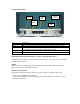
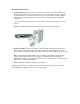
Rear Panel Description Power LAN Ports CATV Connector Reset Button USB Item Power Reset LAN 1-4 USB CATV Description Connect the included power adapter to this port. Use this button to reset the power or restore the default factory settings. Four 10/100 Auto-sensing switch ports (RJ-45). Connect devices on your local area network to these ports (such as a PC, hub, or switch). Connect a USB Cable from your PC to this port. Connect your cable line to this port.
CHAPTER 3 | Installation The EZ Connect™ Wireless Cable Modem Gateway can be installed in any location where you have cable Internet access, and your cable Internet service provider has approved the Gateway. To confirm you meet these 2 criteria points, please contact your cable operator. For general installation please follow the guidelines outlined below to best performance: • • • Keep the Gateway away from any heating devices. Do not place the Gateway in a dusty or wet environment.
Basic Installation Procedure 1. Connect the LAN: You can connect the Gateway to your PC, or to a hub or switch. Run Ethernet cable from one of the LAN ports on the rear of the Gateway to your computer’s network adapter or to another network device. You can use either a standard straight through or cross over Ethernet cable since the Gateway incorporates Auto-MDI MDIX functionality. You can also connect the Gateway to your PC (using a wireless client adapter) via radio signals.
CHAPTER 4 | Configuring your Computer The information outlined in this chapter will guide you through the configuration for the following Operating Systems: • • • • • Windows 95/98 Windows Me Windows 2000 Windows XP Apple Macintosh Configuring Windows 95/98/Me 1. Access your Network settings by clicking [Start], choose [Settings], and then select [Control Panel]. 2. In the Control Panel, locate and double-click the [Network] icon. 3.
Configuring Windows 2000 1. Access your Network settings by clicking [Start], choose [Settings], and then select [Control Panel] 2. In the Control Panel, locate and doubleclick the [Network and Dial-up Connections] icon 3. Locate and double-click the [Local Area Connection] icon for the Ethernet adapter that is connected to the Gateway. When the Status dialog box window opens, click the [Properties] button. 4.
6. Reboot your PC. Configuring a Macintosh Computer You may find that the instructions here do not exactly match your screen. This is because these steps and screen shots were created using Mac OS 10.2. Mac OS 7.x and above are all very similar, but may not be identical to Mac OS 10.2. 1. Pull down the Apple Menu. Click System Preferences and select Network. Make sure that 2. Built-in Ethernet is selected in the Show field. 3. On the TCP/IP tab, select Using DHCP in the Configure field. 4.
CHAPTER 5 | Configuring the EZ Connect™ Wireless Cable Modem Gateway After you have configured TCP/IP on a client computer, use a web browser to configure the EZ Connect™ Wireless Cable Modem Gateway. The Gateway can be configured by any Javasupported browser including Internet Explorer 5.0 or above, or Netscape Navigator 5.0 or above. Using the web management interface, you can configure the Gateway features and view its settings.
Accessing the EZ Connect™ Wireless Cable Modem Gateway’s Web Management To access the EZ Connect™ Wireless Cable Modem Gateway’s web-based management screens, follow the steps below: 1. Launch your web-browser. NOTE: Your computer does not have to be ONLINE to configure the EZ Connect™ Wireless Cable Modem Gateway. 2. In the Address Bar, type: http://192.168.0.1 3. When the Gateway’s Login screen appears, enter the default username and password, and click the [Login] button to access the Gateway.
CHAPTER 6 | Navigating the Web-based Administration The EZ Connect™ Wireless Cable Modem Gateway’s management interface allows you to configure both basic and advanced features and options. Some of these advanced functions include: hacker attack detection, IP and MAC address filtering, intrusion detection, port forwarding setup, virtual DMZ hosts, as well as other advanced functions.
If your password is lost, or you cannot gain access to the user interface, press the Reset button on the rear panel (holding it down for at least five seconds) to restore the factory defaults. From this section you can also configure the RADIUS, TACACS+ and TACACS authentication. Note: only one form of authentication can be enabled at any one time.
Remote Management Allows a remote PC to configure, manage, and monitor the Gateway using a standard web browser. To access the Remote Management configuration page, on the Side Navigation bar, click on [System] link and then click on the [Remote Management] link.
This feature enables the customer to remotely access the web-based administration screen with their username and password (default: cusadmin/password). To enable this feature, check the [Customer Remote Management] checkbox. Remote Management Access Rule This option will allow you to limit who can access the remote management web login from the Internet. The [Everyone] option allows any Internet user to access the web management login.
MAC Spoofing This is an optional configuration that may or may not be required by your cable operator. For more information about MAC Clone/Spoofing please contact your cable operator to determine if this is a required setting. To access the MAC Spoofing configuration page, on the Side Navigation bar, click on [WAN] link and then click on the [MAC Spoofing] link.
Private LAN IP Settings Define the Gateway’s private LAN settings. The IP address configured here is the Gateway’s (default: 192.168.0.1). NOTE: Port Forwarding and Access Control rules will be based on the network scope defined here. If either of these types of rules were previously setup and the Private LAN IP address is changed, then those rules will need to be recreated to reflect the new Private LAN IP network. DHCP Server Settings The Gateway’s DHCP Server can be turned enabled/disabled here.
NOTE: You cannot use the IP address of the Gateway (192.168.0.1 – default IP) in the client address pool. PPTP IP Address Pool When the Gateway is configured to act as a PPTP VPN server in the VPN Settings section, PPTP clients will be assigned IP addresses in this range for their PPTP WAN interface. ROUTING From this section you can configure Static Routes and RIP Control settings. Static Routes Use this section to configure Static Routes on your network.
RIP Control Use this section to configure the RIP control settings. RIP is used by some cable operators to advertise Public LAN IPs to their network. Below is an outline of the RIP control options: 1. RIP Send Version: Options are to send RIP1| RIP2| RIP1 and RIP2| DO NOT SEND. 2. RIP Receive Version: Options are to receive RIP1| RIP2| RIP1 and RIP2| DO NOT RECEIVE. 3. Update Interval: Time period for RIP daemon to send out its routing information to other routers. 4.
1. You will need to confirm the network is setup with a valid Public LAN IP in [LAN] page before they enable the RIP setting. NOTE: The RIP setting is disabled by default. 2. After you confirm the LAN Settings, then you will need to configure the RIP Settings. These settings will need to be configured based on how your cable operator network is set up. WIRELESS This section allows you to configure the Gateway’s built-in 54 Mbps 802.11g Access Point.
The Wireless Mode can be set to Mixed (default), 11B only, 11B+ only, or 11G only. Also, the Gateway’s wireless interface can be disabled if not being used. Channel and SSID You must specify a common radio channel and SSID (Service Set ID) to be used by the Gateway and all of your wireless clients. Be sure you configure all of your clients to the same values.
If you are transmitting sensitive data across wireless channels, you should enable either Wired Equivalent Privacy (WEP) or WiFi Protected Access (WPA) encryption. Encryption requires you to use the same set of encryption/decryption keys for the Gateway and all of your wireless clients. To access the Encryption configuration page, on the Side Navigation bar, click on [Wireless] link and then click on the [Encryption] link. WEP Select [WEP] from the [Encryption Type] drop down menu.
keys. Simply configure the Default Key to the one key that you will be using across your network. On the wireless clients, you can use the passphrase option, and client utility will generate the same 4 keys – or you can manually type in the selected KEY that is configured on the Gateway. For more security, you can use 128-bit WEP encryption. To use this mode, click the [128 Bit Encryption] option and the configuration section will be displayed.
You can also configure a [Device Name] that is associated with a specific MAC address. In doing this, you can easily recognize the computers that you are in your access list. NOTE: MAC filtering only applies to Wireless Clients. NAT Network Address Translation (NAT) allows multiple users at your local site to access the Internet through a single public IP address. Port Forwarding The Gateway supports port forwarding that enables customers to host servers on their LAN.
This Port Forwarding function supports 2 types of Services: • • Predefined Service Customer Defined Service Predefined Service The Predefined Service option has a pull-down menu with several popular Service Applications, such as HTTP (80), FTP (20/21), and AIM/ICQ (5190). To configure Port Forwarding with a Predefined Service rule, follow the steps below: 1. Select the [Service] that you want to have access through the firewall to your LAN from the pull-down menu. 2.
4. Click the [Apply] button to save your changes and return to the Port Forwarding main screen Customer Defined Service Rule (Custom) The Customer Defined Service section allows you to custom configure a Port Forwarding rule with any Traffic type (TCP/UDP/TCP and UDP), Public Port, and Private Port. To configure this custom option, please follow the steps below: 1. Enter in a Description [Name] for this custom setting 2. Configure the Traffic or Data [Type] that you want to forward.
Remote IPs: Public Port: Private Port: Any (allow access to any public IP) 8000 80 With this configuration, all HTTP (Web) TCP traffic on port 8000 from any IP Address from the WAN side will be redirected through the firewall to the Internal Server (192.168.0.100) on port 80. NOTE: This configuration is useful because you don’t have to reconfigure your web server to accept traffic on a different port, you can do this configuration on the Gateway.
The second section is used to configure Access Rules for the Private LAN to the Internet. These rules will block services on the private LAN to the Internet. From this section, you can also choose to have the Gateway to [Respond to Ping on Internet WAN Port]. If you check this option, the Gateway will respond to PING requests to the WAN IP address. By default this option is enabled.
4. Select the [LAN IPs] that you want this access rule to apply to. You can choose to apply this rule to Any IP Address, a Single IP Address, or a Range of IP Addresses. a. Any IP Address [Any] – choose this option to block all LAN clients. You don’t need to configure the [Start IP] or [End IP] options. b. Single IP Address [Single address] – choose this option to block a single LAN client. Enter the LAN IP address of the PC in the [Start IP] field. c.
7. When your configuration is complete, click the [Apply] button to save your changes and return to the main Access Control page. Special Application Some applications, such as Internet gaming, videoconferencing, Internet telephony, and others require multiple connections. Rules are based on the port or range of ports that the application sends data to the server on (destination port).
6. Set the [Interval] of the rule. This is the time in between the outgoing and incoming data traffic. NOTE: If you set this value too low, the incoming ports will be closed before the return data arrives at the firewall and the connection will be broken and the application will not work. 7.
3. Enter in a new keyword or URL address that you want to block in the [Keyword/Domain Name] input box. 4. Press the [Add Keyword] button to save this keyword or URL. 5. The new keyword or URL address would be listed in the text box below. NOTE: This list will support 50 Keywords or URLs. If you want a PC on your network to bypass these rules you will need to set that PC as an Exempted PC/Trusted Host.
There are 3 sections to configure on this page: • • • Email Alerting Syslog Alerting Alerting Schedule To enable the Email Alert feature, click the [Enable Email Alerting] checkbox. Follow the steps below to configure the Email Alert feature: 1. Enter in your SMTP Server Address (this is also referred to as the outgoing mail server) 2. Enter in the [Sender’s E-mail Address] – this is the email address that is associated with the outgoing mail server account. 3. Enter in your email [User Name]. 4.
5. To add an email address to the Alert List, click the [Add] button. The configuration page shown below will be displayed: NOTE: The email alert feature will allow you to send email alerts to 4 different email accounts. For example you could send an email to your home, work, and school email address. 6. Enter in the [Name] of the person/account that you want to send this to 7. Enter in the [Recipient’s Email Address] as the email address you want to send the alert to 8.
Immediate Alerts can be generated for both the email and Syslog alerts. To configure the type of Alert that you want to get: - An Intrusion is detected – this is a hacker attack attempt from the WAN - Attempts to access a blocked site – alert to any attempts to access a site or keyword listed in your URL/Blocking list.
Locally Backup Settings to Configuration File The first Tools option is to [Back Up] your configuration settings of your Gateway. This includes, but is not limited to, Port Forwarding, Special Application, and Alert Emails. To save the Gateway settings to a configuration file, follow the steps below: 1. Click on the [Back Up] button 2. Click [Save] on the File Download dialog box 3. Save this file to a location on your network or local hard drive.
3. Click [OK] to confirm the restore process 4. To complete the Restore process the Gateway will reboot. NOTE: This file format (.cfg) is the only format that you can use to restore settings from. This is format that is provided by the Backup option. Remotely Backup/Restore Gateway Settings To backup your configuration settings of your Gateway to a TFTP server, select the [Backup] option. To save the Gateway settings to a remotely stored configuration file, follow the steps below: 1.
3. To complete the Restore process the Gateway will reboot. Reboot In the event that the system stops responding correctly or functioning properly, you can perform a reboot. To access the Reboot option page, on the Side Navigation bar, click on [Tools] link and then click on the [Reboot] link. To reboot the Gateway, follow the steps below: 1. Click the [Apply] button 2. Click [OK] on the confirmation dialog box 3. The Gateway will reboot.
VPN The VPN section allows you to setup VPN end points on the Gateway. By doing so, an encrypted tunnel will be established between the Gateway and the remote VPN end point. To access the VPN configuration page, on the Side Navigation bar, click on [VPN] link. The Gateway supports 3 types of VPN termination: • IPSec • PPTP • L2TP over IPSec To enable a VPN end point protocol, deselect the appropriate option on the VPN settings page and click [Apply]. By default, all VPN end point options are disabled.
3. Click the [Apply] button to save your changes 4. On the Side Navigation bar, click on the [Access Control] link 5. Enable LAN clients that will access the IPSec VPN by adding them to the VPN Access List. There are two ways to add a LAN client to the VPN Access List. Either select the radio button next to an [Auto-Learned CPE Device] or manually enter the LAN clients MAC address in the [Manually-Added CPE Devices] section, then select [Add] 6.
a. Either the Gateway’s Private LAN IP address or Public LAN IP address can be configured as the end point for the VPN tunnel. Select either [Protect Private Lan] or [Protect Public Lan] to enable the entire Private or Public LAN to be part of the VPN tunnel and the respective Gateway LAN IP address will populate the [Intranet Address] and [Intranet Subnet Mask] fields. b. Enter the [Local ID] which must match the “Remote ID” of the remote VPN end point. c.
g. Enter the [Authentication method]. Currently, the Gateway only supports [Preshared Key]. h. Enter the [IKE HASH]. The options are MD5 | SHA. i. Enter the [IKE Encryption]. The options are DES | IDEA | BLOWFISH | RC5 | 3DES. j. Enter the [IPSec Operation]. The options are ESP | AH. k. Enter the [ESP Transform]. The options are DES | IDEA | BLOWFISH | RC5 | 3DES. This option is only available when ESP [IPSec Operation] is selected. l. Enter the [ESP AUTH]. The options are NONE | MD5 | SHA | DES.
9. The [Status] should now be [Phase 2 Completed]. Create a PPTP VPN Tunnel To enable and configure a PPTP server on the Gateway, follow the steps below. Note that remote PPTP clients that connect into the Gateway will be assigned IP addresses from the PPTP IP Address Pool on the LAN Settings page for their PPTP WAN interface. 1. On the Side Navigation bar, click on the [VPN] link 2. On the VPN settings page, deselect the [Disable PPTP VPN Functions] option 3.
6. Enter the [User Name] and [Password]. User Name must be at least 3 characters and password must be at least 6 characters. 7. Click [Apply] to save the settings. You will be returned to the PPTP/L2TP Configuration page. Create a L2TP over IPSec VPN Tunnel To enable and configure a L2TP over IPSec end point, follow the steps below. 1. First, follow the steps to setup an IPSec tunnel in the Creating an IPSec VPN Tunnel section above. 2.
STATUS The Status screen summarizes important information about the Gateway including WAN/LAN connection status, Wireless settings, software version and hardware versions, and uptime statistics. The Network Log shows both firewall and network activity The LAN Client Log shows the clients connected to the Gateway and the type of connection (Ethernet or Wireless). This also shows the IP address assigned to the client and the MAC Address of the client’s network adapter.
The Cable Modem System Event Log shows diagnostic information about your connection and cable system. The Cable Status page shows the users the initialization process the SMC8014W-G has been through, and also includes the information about the downstream channel and the upstream channel the modem is connected on.
APPENDIX A | Telnet and SSH CLI Commands Refer to the Remote Management section in Chapter 6 to enable and configure Telnet and SSH settings. Refer to the 8014 CLI document for command specifics. To remotely access the CLI of the SMC8014W-G via Telnet, open a DOS/Command Prompt and type: telnet IP remote mgmt port Enter • • • • • NOTE: Telnet remote management is not enabled by default.
APPENDIX B | Troubleshooting This appendix describes common problems you may encounter and possible solutions to them. B.1 | Verify you are connected to the EZ Connect™ Wireless Cable Modem Gateway If you are unable to access the Gateway’s web-based administration pages, then you may not be properly connected or configured. The screen shots in this section were taken on a Windows 2000 machine, but the same steps will apply to Windows 95/98/Me/XP.
B.3 | I have another IP Address displayed If you have another IP address listed, then the PC may not be configured for a DHCP connection. Please refer to Chapter 4 | Configure your Computer for information. Once you have confirmed your computer is configured for DHCP, follow the steps below. 1. Open a DOS window as described above. 2. Type “ipconfig /release” (without the quotes) 3.
B.4 | Pinging the EZ Connect™ Wireless Cable Modem Gateway To verifying Your TCP/IP Connection is configured properly and you are able to access the EZ Connect™ Wireless Cable Modem Gateway’s web-based management screens – you can use the ‘Ping’ command in DOS. To access the DOS dialog window please follow the steps below: 1. Click Start, then choose Run 2. Windows 98/Me users type “command” and click the [OK] button. Windows 2000/XP users type “cmd” and click the [OK] button. 3.
B.5 | Symptom / Action Troubleshooting The Gateway can be easily monitored through panel indicators to identify problems. Please refer to Chapter 2 – Section 2.0 | LED Definitions to confirm you have the correct LED status. If not, then refer to the symptoms and actions outlined below: SYMPTOM: Power LED is Off ACTION: • Check connections between the Gateway, the external power supply, and the wall outlet.
SYMPTOM: Internet users can not access my service/server hosted on a LAN computer ACTION: • Configure a Port Forwarding rule as described in the NAT section of CHAPTER 6. • Contact your cable operator for assistance if you do not have this option available in your login. SYMPTOM: My Gateway is wireless enabled and I can not connect to the wireless network ACTION: • Confirm that your computer’s wireless adapter is configured with the same SSID and encryption (if enabled) of the Gateway.
APPENDIX C | Technical Specifications Standards • 802.3 10BaseT Ethernet • 802.3u 100BaseTX Fast Ethernet • 802.11g WAN Interface • F-type RF Connector LAN Interfaces • 4 – 10BASE-T/100BASE-TX RJ-45 ports • 1 – USB 1.1 Type B Connector • 1 – 801.11g Access Point Wireless Interface • 54Mbps IEEE 802.11g Wireless LAN • WPA encryption • 64/128 bit WEP encryption • Auto data rate of: 54, 48, 36, 24, 18, 12, 9, 6 Mbps (802.11g) and 11, 5.5, 2, and 1 Mbps (802.11b) Cable Modem Interface • DOCSIS 1.1 and 2.
APPENDIX D | Compliances FCC Interference Statement This equipment has been tested and found to comply with the limits for a Class B digital device pursuant to Part 15 of the FCC Rules. These limits are designed to provide reasonable protection against radio interference in a commercial environment. This equipment can generate, use and radiate radio frequency energy and, if not installed and used in accordance with the instructions in this manual, may cause harmful interference to radio communications.
APPENDIX E | Technical Support At this time, the SMC8014W-G is only distributed through cable operators. Contact your cable operator with any technical support needs you may have. PHONE From U.S.A. and Canada (24 hours a day, 7 days a week) • (800) SMC-4-YOU • (949) 679-8000 • Fax: (949) 679-1481 From Europe (8:00 AM - 5:30 PM UK Time) • 44 (0) 118 974 8700 • Fax: 44 (0) 118 974 8701 INTERNET E-mail addresses: • techsupport@smc.com • european.techsupport@smc-europe.com Driver updates: • http://www.smc.
SMC Networks, Inc. 38 Tesla Irvine, CA 92618 Rev. 1.0 – 4.01.