EZ Connect™ Cable Modem Gateway Install Guide -1- SMC8014
Copyright Information furnished by SMC Networks, Inc. (SMC) is believed to be accurate and reliable. However, no responsibility is assumed by SMC for its use, nor for any infringements of patents or other rights of third parties which may result from its use. No license is granted by implication or otherwise under any patent or patent rights of SMC. SMC reserves the right to change specifications at any time without notice. Copyright © 2006 by SMC Networks, Inc.
TABLE OF CONTENTS CHAPTER 1 | Introduction Features and Benefits Package Contents Minimum Requirements CHAPTER 2 | Getting to know the EZ Connect™ Cable Modem Gateway LED Indicators Rear Panel Description Resetting and Restoring the EZ Connect™ Cable Modem Gateway CHAPTER 3 | Installation Basic Installation Procedure CHAPTER 4 | Configuring your Computer Configuring Windows 95/98/Me Configuring Windows 2000 Configuring Windows XP Configuring a Macintosh Computer CHAPTER 5 | Configuring the EZ Connect™ Cable
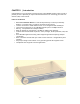
CHAPTER 1 | Introduction Congratulations on your purchase of the EZ Connect™ Cable Modem Gateway. SMC is proud to provide you with a powerful yet simple communication device for connecting your local area network (LAN) to the Internet. Features and Benefits • • • • • • • • • • EZ 3-Click Installation Wizard - A new and improved way to install your Gateway Modem. In 3 simple clicks, you will be connected to the Internet.
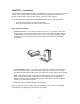
Package Contents Before installing the EZ Connect™ Cable Modem Gateway, verify that you have the items listed under below. Also be sure that you have the necessary cabling. If any of the items are missing or damaged, contact your local SMC distributor. • • • • • 1 - EZ Connect™ Cable Modem Gateway 1 - Power adapter (12V/1.
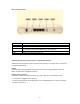
CHAPTER 2 | Getting to Know the EZ Connect™ Cable Modem Gateway The EZ Connect™ Cable Modem Gateway is the perfect all in one solution, for the home or business environment. This full-featured device has: • • • • • • An approved DOCSIS 1.1 and 2.0 Cable modem Advanced SPI Firewall Gateway Comprehensive LEDs for network status and troubleshooting Reset Button 4 – 10/100 Mbps Auto-Sensing LAN ports with Auto-MDI MDIX feature 1 – USB 1.
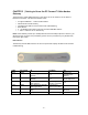
Rear Panel Description Item Power Reset LAN 1-4 USB CATV Description Connect the included power adapter to this port. Use this button to reset the power or restore the default factory settings. Four 10/100 Auto-sensing switch ports (RJ-45). Connect devices on your local area network to these ports (such as a PC, hub, or switch). Connect a USB Cable from your PC to this port. Connect your cable line to this port.
CHAPTER 3 | Installation The EZ Connect™ Cable Modem Gateway can be installed in any location where you have cable Internet access, and your cable Internet service provider has approved the Gateway. To confirm you meet these 2 criteria points, please contact your cable operator. For general installation please follow the guidelines outlined below to best performance: • • Keep the Gateway away from any heating devices. Do not place the Gateway in a dusty or wet environment. Basic Installation Procedure 1.
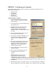
CHAPTER 4 | Configuring your Computer The information outlined in this chapter will guide you through the configuration for the following Operating Systems: • • • • • Windows 95/98 Windows Me Windows 2000 Windows XP Apple Macintosh Configuring Windows 95/98/Me 1. Access your Network settings by clicking [Start], choose [Settings], and then select [Control Panel]. 2. In the Control Panel, locate and double-click the [Network] icon. 3.
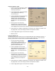
Configuring Windows 2000 1. Access your Network settings by clicking [Start], choose [Settings], and then select [Control Panel] 2. In the Control Panel, locate and doubleclick the [Network and Dial-up Connections] icon 3. Locate and double-click the [Local Area Connection] icon for the Ethernet adapter that is connected to the Gateway. When the Status dialog box window opens, click the [Properties] button. 4.
6. Reboot your PC. Configuring a Macintosh Computer You may find that the instructions here do not exactly match your screen. This is because these steps and screen shots were created using Mac OS 10.2. Mac OS 7.x and above are all very similar, but may not be identical to Mac OS 10.2. 1. Pull down the Apple Menu. Click System Preferences and select Network. Make sure that 2. Built-in Ethernet is selected in the Show field. 3. On the TCP/IP tab, select Using DHCP in the Configure field. 4.
CHAPTER 5 | Configuring the EZ Connect™ Cable Modem Gateway After you have configured TCP/IP on a client computer, use a web browser to configure the EZ Connect™ Cable Modem Gateway. The Gateway can be configured by any Java-supported browser including Internet Explorer 5.0 or above, or Netscape Navigator 5.0 or above. Using the web management interface, you can configure the Gateway features and view its settings.
Accessing the EZ Connect™ Cable Modem Gateway’s Web Management To access the EZ Connect™ Cable Modem Gateway’s web-based management screens, follow the steps below: 1. Launch your web-browser. NOTE: Your computer does not have to be ONLINE to configure the EZ Connect™ Cable Modem Gateway. 2. In the Address Bar, type: http://192.168.0.1 3. When the Gateway’s Login screen appears, enter the default username and password, and click the [Login] button to access the Gateway.
CHAPTER 6 | Navigating the Web-based Administration The EZ Connect™ Cable Modem Gateway’s management interface allows you to configure both basic and advanced features and options. Some of these advanced functions include: hacker attack detection, IP and MAC address filtering, intrusion detection, port forwarding setup, virtual DMZ hosts, as well as other advanced functions.
LAN IP Use the LAN section to configure the LAN IP address for the Gateway and to enable the DHCP server for dynamic client address allocation. You can also configure the Lease Time for the DHCP clients on your network. Private LAN IP Settings Define the Gateway’s private LAN settings. The IP address configured here is the Gateway’s (default: 192.168.0.1). NOTE: Port Forwarding and Access Control rules will be based on the network scope defined here.
To access the Port Forwarding configuration page, on the Side Navigation bar, click on [NAT] link and then click on the [Port Forwarding] link. This Port Forwarding function supports 2 types of Services: • • Predefined Service Customer Defined Service Predefined Service The Predefined Service option has a pull-down menu with several popular Service Applications, such as HTTP (80), FTP (20/21), and AIM/ICQ (5190). To configure Port Forwarding with a Predefined Service rule, follow the steps below: 1.
Customer Defined Service Rule (Custom) The Customer Defined Service section allows you to custom configure a Port Forwarding rule with any Traffic type (TCP/UDP/TCP and UDP), Public Port, and Private Port. To configure this custom option, follow the steps below: 1. Enter in a Description [Name] for this custom setting 2. Configure the Traffic or Data [Type] that you want to forward. The options are TCP | UDP | TCP/UDP. 3. Set the [LAN Server IP] of the PC that you want this traffic/data redirected to 4.
With this configuration, all HTTP (Web) TCP traffic on port 8000 from any IP Address from the WAN side will be redirected through the firewall to the Internal Server (192.168.0.100) on port 80. NOTE: This configuration is useful because you don’t have to reconfigure your web server to accept traffic on a different port, you can do this configuration on the Gateway. FIREWALL The Gateway provides a stateful inspection firewall (SPI), which is designed to protect against Denial of Service (DoS) attacks.
The second section is used to configure Access Rules for the Private LAN to the Internet. These rules will block services on the private LAN to the Internet. For convenience, each Access Control section includes 2 filtering options: • • Predefined Filtering Customer Defined Filtering Predefined Filtering Access Rule: 1. On the Side Navigation bar, click on [Firewall] then select [Access Control] 2. Under the Predefined Section, click on the [Add] button 3.
3. On the Customer Defined Filter page, define a Name for the service/application that you want to block. NOTE: The Name is only for reference purposes. 4. Then select the protocol type from the pull-down menu that they would like to block. The options are TCP | UDP | TCP/UDP. 5. Select the [LAN IPs] that you want this access rule to apply to. You can choose to apply this rule to Any IP Address, a Single IP Address, or a Range of IP Addresses. a.
To configure a Special Application Rule, follow the steps outlined below: 1. On the Side Navigation bar, click on [Firewall] then select [Special Application] 2. Click on the [Add] button on the Special Application page to access the [Trigger] configuration section. 3. Enter in the [Name] that you want to use for this rule. 4. In the [Type] pull-down menu, select the data/traffic type that this rule will apply to. The options are TCP | UDP. 5.
URL Blocking This section allows you to control the content network. This feature is good for both business and parents looking to control the content accessible from a web browser. To access the URL Blocking configuration page, on the Side Navigation bar, click on [Firewall] link and then click on the [URL Blocking] link. To enable this option, click the [Enable Keyword Blocking] checkbox To configure URL blocking, follow the steps outlined below: 1.
To access the Schedule Rule configuration page, on the Side Navigation bar, click on [Firewall] link and then click on the [Schedule Rule] link. To enable this option, click the [Enable Schedule Function] checkbox. To configure Schedule Rules, follow the steps outlined below: 1. 2. 3. 4. 5. On the Side Navigation bar, click on [Firewall] then select [Schedule Rule] In the [Week Day] table check the Days that you want to apply URL/Keyword Blocking. Define the appropriate settings for a schedule rule.
TOOLS The Tools menu allows a user to Reboot the Gateway. To reboot the Gateway, follow the steps below: 1. Click the [Apply] button 2. Click [OK] on the confirmation dialog box 3. The Gateway will reboot. NOTE: The Reboot will be complete when the power LED stops blinking. STATUS The Status screen summarizes important information about the Gateway including WAN/LAN connection status, software version and hardware versions, and uptime statistics. The Network Log shows both firewall and network activity.
The LAN Client Log shows the clients connected to the Gateway and the type of connection. This also shows the IP address assigned to the client and the MAC Address of the client’s network adapter. The Cable Modem System Event Log shows diagnostic information about your connection and cable system.
APPENDIX A | Telnet and SSH CLI Commands Refer to the 8014 CLI document for command specifics. APPENDIX B | Troubleshooting This appendix describes common problems you may encounter and possible solutions to them. B.1 | Verify you are connected to the EZ Connect™ Cable Modem Gateway If you are unable to access the Gateway’s web-based administration pages, then you may not be properly connected or configured.
Confirm that you have a good link light on the Gateway’s port to which this computer is connected. If not, please try another cable. If you have a good link light, please open up a DOS window as described in section A.1 and type “ipconfig /renew” (without the quotes) If you are still unable to get an IP Address from the Gateway, reinstall your network adapter. If anti-virus software is running on your computer, disable it before reinstalling the network adapter.
settings will be erased! If you still cannot access the Gateway once you have reset it, please contact your cable operator for assistance. B.4 | Pinging the EZ Connect™ Cable Modem Gateway To verifying Your TCP/IP Connection is configured properly and you are able to access the EZ Connect™ Cable Modem Gateway’s web-based management screens – you can use the ‘Ping’ command in DOS. To access the DOS dialog window please follow the steps below: 1. Click Start, then choose Run 2.
B.5 | Symptom / Action Troubleshooting The Gateway can be easily monitored through panel indicators to identify problems. Please refer to Chapter 2 – Section 2.0 | LED Definitions to confirm you have the correct LED status. If not, then refer to the symptoms and actions outlined below: SYMPTOM: Power LED is Off ACTION: • Check connections between the Gateway, the external power supply, and the wall outlet.
ACTION: • Configure a Special Application rule as described in the Firewall section of CHAPTER 6. • Confirm that an Access Control (Port Filtering) rule is not blocking the ports used by the application. Refer to the Firewall section of CHAPTER 6. • Contact your cable operator for assistance if you do not have this option available in your login.
APPENDIX C | Technical Specifications Standards • 802.3 10BaseT Ethernet • 802.3u 100BaseTX Fast Ethernet • 802.11g Management • Browser-based management Indicator Panel • Power – Green • Diagnostics – Green • Cable – Green • Traffic - Green • WLAN – Green • LAN (1-4) (10Mbps - Amber / 100 Mbps - Green) • USB - Green WAN Interface • F-type RF Connector LAN Interfaces • 4 – 10BASE-T/100BASE-TX RJ-45 ports • 1 – USB 1.1 Type B Connector • 1 – 801.11g Access Point Wireless Interface • 54Mbps IEEE 802.
APPENDIX D | Compliances FCC Interference Statement This equipment has been tested and found to comply with the limits for a Class B digital device pursuant to Part 15 of the FCC Rules. These limits are designed to provide reasonable protection against radio interference in a commercial environment. This equipment can generate, use and radiate radio frequency energy and, if not installed and used in accordance with the instructions in this manual, may cause harmful interference to radio communications.
APPENDIX E | Technical Support At this time, the SMC8014 is only distributed through cable operators. Contact your cable operator with any technical support needs you may have. PHONE From U.S.A. and Canada (24 hours a day, 7 days a week) • (800) SMC-4-YOU • (949) 679-8000 • Fax: (949) 679-1481 From Europe (8:00 AM - 5:30 PM UK Time) • 44 (0) 118 974 8700 • Fax: 44 (0) 118 974 8701 INTERNET E-mail addresses: • techsupport@smc.com • european.techsupport@smc-europe.com Driver updates: • http://www.smc.
SMC Networks, Inc. 38 Tesla Irvine, CA 92618 Rev. 1.0 – 4.02.