
Switch User Manual


I
NSTALLATION
3-2
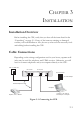
1. Using standard telephone cable, connect the CPE’s RJ-11 LINE port
to the RJ-11 telephone wall jack providing the VDSL service.
2. Connect a telephone or fax machine to the RJ-11 port on the CPE
labeled PHONE.
3. For the Ethernet connection, make sure you have installed a
10BASE-T or 100BASE-TX network adapter card in the computer.
4. Prepare straight-through shielded or unshielded twisted-pair cables
with RJ-45 plugs at both ends. Use 100-Ohm Category 3, 4, or 5 cable
for a 10 Mbps Ethernet connection, or Category 5 cable for a
100 Mbps connection.
5. Connect one end of the cable to the RJ-45 port of the network
interface card, and the other end to the RJ-45 LAN port on the CPE.
When inserting an RJ-45 plug, be sure the tab on the plug clicks into
position to ensure that it is properly seated.
Caution: Do not plug a phone jack connector into any RJ-45 port. Use
only twisted-pair cables with RJ-45 connectors that conform to
FCC standards.
Notes: 1. When connecting to a hub or switch, use crossover cabling.
(Refer to “Crossover Wiring” on page B-4 for a description of
crossover cable.)
2. Make sure the twisted-pair cable connected to the CPE LAN
port does not exceed 100 meters (328 feet).
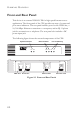
Powering On
Plug the power adapter cord into the DC 12V power socket on the CPE,
then plug the power adapter directly into a power outlet. Check the LED
marked POWER on the front panel to be sure it is on.