
24-Port Layer 3 Switch Management Guide


C
ONFIGURING
THE
S
WITCH
3-18
You can manually configure a specific IP address, or direct the device to
obtain an address from a BOOTP or DHCP server. Valid IP addresses
consist of four decimal numbers, 0 to 255, separated by periods. Anything
outside this format will not be accepted by the CLI program.
Command Usage
• This section describes how to configure a single local interface for initial
access to the switch. To configure multiple IP interfaces on this switch,
you must set up an IP interface for each VLAN (page 3-155).
• To enable routing between the different interfaces on this switch, you
must enable IP routing (page 3-154).
• To enable routing between the interfaces defined on this switch and
external network interfaces, you must configure static routes (page 3-172)
or use dynamic routing; i.e., either RIP (page 3-175) or OSPF
(page 3-186).
• The precedence for configuring IP interfaces is the IP / General /
Routing Interface menu (page 3-155), static routes (page 3-172), and then
dynamic routing.
Command Attributes
• VLAN – ID of the configured VLAN (1-4094, no leading zeroes). By
default, all ports on the switch are members of VLAN 1. However, the
management station can be attached to a port belonging to any VLAN,
as long as that VLAN has been assigned an IP address.
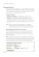
• IP Address Mode – Specifies whether IP functionality is enabled via
manual configuration (Static), Dynamic Host Configuration Protocol
(DHCP), or Boot Protocol (BOOTP). If DHCP/BOOTP is enabled, IP
will not function until a reply has been received from the server. Requests
will be broadcast periodically by the switch for an IP address. (DHCP/
BOOTP values can include the IP address, subnet mask, and default
gateway.)
• IP Address – Address of the VLAN interface through which the
management station is attached. Valid IP addresses consist of four
numbers, 0 to 255, separated by periods. (Default: 0.0.0.0)