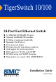
TigerSwitch 10/100 24-Port Fast Ethernet Switch ◆ ◆ ◆ ◆ ◆ ◆ ◆ ◆ ◆ ◆ 24 10BASE-T/100BASE-TX ports Optional 1000BASE-SX modules 8.
TigerSwitch 10/100 Installation Guide From SMC’s Tiger line of feature-rich workgroup LAN solutions 6 Hughes Irvine, CA 92618 Phone: (949) 707-2400 December 2000 Pub. # F2.
Information furnished by SMC Networks, Inc. (SMC) is believed to be accurate and reliable. However, no responsibility is assumed by SMC for its use, nor for any infringements of patents or other rights of third parties which may result from its use. No license is granted by implication or otherwise under any patent or patent rights of SMC. SMC reserves the right to change specifications at any time without notice. Copyright © 2000 by SMC Networks, Inc. 6 Hughes Irvine, CA 92618 All rights reserved.
LIMITED WARRANTY Limited Warranty Limited Warranty Statement: SMC Networks, Inc. (“SMC”) warrants its products to be free from defects in workmanship and materials, under normal use and service, for the applicable warranty term. All SMC products carry a standard 90-day limited warranty from the date of purchase from SMC or its Authorized Reseller.
LIMITED WARRANTY WARRANTIES EXCLUSIVE: IF AN SMC PRODUCT DOES NOT OPERATE AS WARRANTED ABOVE, CUSTOMER’S SOLE REMEDY SHALL BE REPAIR OR REPLACEMENT OF THE PRODUCT IN QUESTION, AT SMC’S OPTION. THE FOREGOING WARRANTIES AND REMEDIES ARE EXCLUSIVE AND ARE IN LIEU OF ALL OTHER WARRANTIES OR CONDITIONS, EXPRESS OR IMPLIED, EITHER IN FACT OR BY OPERATION OF LAW, STATUTORY OR OTHERWISE, INCLUDING WARRANTIES OR CONDITIONS OF MERCHANTABILITY AND FITNESS FOR A PARTICULAR PURPOSE.
COMPLIANCES FCC - Class A This equipment generates, uses, and can radiate radio frequency energy and, if not installed and used in accordance with the instruction manual, may cause interference to radio communications. It has been tested and found to comply with the limits for a Class A computing device pursuant to Subpart B of Part 15 of FCC Rules, which are designed to provide reasonable protection against such interference when operated in a commercial environment.
COMPLIANCES Industry Canada - Class A This digital apparatus does not exceed the Class A limits for radio noise emissions from digital apparatus as set out in the interference-causing equipment standard entitled “Digital Apparatus,” ICES-003 of the Department of Communications.
COMPLIANCES Safety Compliance Warning: Fiber Optic Port Safety When using a fiber optic port, never look at the transmit laser while it is powered on. Also, never look directly at the fiber TX port and fiber cable ends when they are powered on. Avertissment: Ports pour fibres optiques - sécurité sur le plan optique Ne regardez jamais le laser tant qu'il est sous tension.
COMPLIANCES Wichtige Sicherheitshinweise (Germany) 1. Bitte lesen Sie diese Hinweise sorgfältig durch. 2. Heben Sie diese Anleitung für den späteren Gebrauch auf. 3. Vor jedem Reinigen ist das Gerät vom Stromnetz zu trennen. Verwenden Sie keine Flüssigoder Aerosolreiniger. Am besten eignet sich ein angefeuchtetes Tuch zur Reinigung. 4. Die Netzanschlu ßsteckdose soll nahe dem Gerät angebracht und leicht zugänglich sein. 5. Das Gerät ist vor Feuchtigkeit zu schützen. 6.
TABLE 1 OF CONTENTS About the TigerSwitch 10/100 . . . . . . . . . . . . . . 1-1 Overview . . . . . . . . . . . . . . . . . . . . . . . . . . . . . . . . . . . . . . . 1-1 Switch Architecture . . . . . . . . . . . . . . . . . . . . . . . . . . . . 1-2 Management Options . . . . . . . . . . . . . . . . . . . . . . . . . . 1-2 Description of Hardware . . . . . . . . . . . . . . . . . . . . . . . . . . . . 1-3 10BASE-T/100BASE-TX Ports (SMC6724L2) . . . . . . . . . . 1-3 Status LEDs . . . . . . . . . . . .
TABLE OF CONTENTS 10 Mbps Ethernet Collision Domain . . SMC 5-4-3 Rule . . . . . . . . . . . . . Maximum Ethernet Cable Distance Application Notes . . . . . . . . . . . . . . . . . . . . 3 . . . . . . . . . . . . . . . . . . . . . . . . . . . . . . . . .. .. .. .. .. .. .. .. .. .. .. .. .. .. .. .. . . . . . . . . .. .. .. .. .. .. .. .. .. .. .. .. .. .. .. .. . . . . . . . . . . . . . . . . . . . . . . . . . . . . . . . . . . . . . . . . . . . . . . . . . . . . . . . .
TABLE OF CONTENTS Console Port to 9-Pin COM Port on PC . . . . . . . . . . . . .B-6 Console Port to 25-Pin DCE Port on Modem . . . . . . . . .B-6 Console Port to 25-Pin DTE Port on PC . . . . . . . . . . . . .B-7 C Specifications . . . . . . . . . . . . . . . . . . . . . . . . . . . . C-1 Physical Characteristics . . . . . . . . . . Switch Features . . . . . . . . . . . . . . . . Management Features . . . . . . . . . . . Standards . . . . . . . . . . . . . . . . . . . . Compliances . . . . . . . . . . . .
TABLE OF CONTENTS viii
CHAPTER 1 ABOUT THE TIGERSWITCH 10/100 Overview SMC’s TigerSwitch™ 10/100 is a fast Ethernet switch with 24 10BASE-T/100BASE-TX ports, plus two slots for optional slide-in 1000BASE-SX modules. There is also an SNMP-based management agent embedded on the main board. This agent supports both in-band and out-of-band access for managing the switch. Figure 1-1. SMC6724L2 Front Panel Figure 1-2. SMC6724L2 Rear Panel Figure 1-3.
ABOUT THE TIGERSWITCH 10/100 Switch Architecture The TigerSwitch employs a high-speed switching fabric. This design allows for simultaneous transport of multiple packets at low latency on all ports. It also uses store-and-forward switching to ensure maximum data integrity. In this mode, the entire packet must be received into a port buffer and checked for validity before being forwarded. This prevents errors from being propagated throughout the network.
ABOUT THE TIGERSWITCH 10/100 Description of Hardware 10BASE-T/100BASE-TX Ports (SMC6724L2) These ports are dual-speed RJ-45 ports. Ports 1 through 23 are labeled with an “x” to indicate that they have a built-in crossover (MDI-X). Workstations and servers can be connected to these ports with straight-through cable. Port 24 is switch-selectable (MDI-X or MDI).
ABOUT THE TIGERSWITCH 10/100 Status LEDs The LEDs, which are located on the front panel for easy viewing, are shown below and described in the following table. Figure 1-4. Port and System LEDs Port and System Status LEDs LED Condition Status Power On Switch is receiving power. On Port has established a valid network connection. Yellow Valid 10 Mbps connection. Green Valid 100 Mbps connection. Flashing Traffic is passing through the port. FDX On Port is operating at full duplex.
ABOUT THE TIGERSWITCH 10/100 Switch Management This switch includes a built-in management agent that offers a variety of management options, including SNMP, RMON and a Web-based interface. The switch also includes an RS-232 serial port for out-of-band management. A PC may be connected to this port for configuration and monitoring purposes out-of-band via a full-handshaking null-modem cable. The management agent provides a wide range of advanced performance-enhancing features.
ABOUT THE TIGERSWITCH 10/100 port, or in-band via the Web interface, Telnet, or SNMP network management software. VLANs The TigerSwitch 10/100 supports up to 64 VLANs. A Virtual LAN is a collection of network nodes that share the same collision domain regardless of their physical location or connection point in the network. By segmenting your network into VLANs, you can: • Eliminate broadcast storms which severely degrade performance in a flat network.
ABOUT THE TIGERSWITCH 10/100 Optional Media Extender Module Optional 1000BASE-SX Module (SMC6724L2GSSC) Figure 1-5. Single-Port 1000BASE-SX Gigabit Module Using fiber optic cable, the 1000BASE-SX port can be connected to a remote site up to 550 m (1805 ft.) away. The 1000BASE-SX Gigabit module operates at 1 Gbps, with support for full-duplex mode and flow control. This module is fitted with an SC connector, but you can attach an ST plug to the switch using the SC-ST Converter (Part Number: 99-012034-091).
ABOUT THE TIGERSWITCH 10/100 Features and Benefits Connectivity ◆ 24 dual-speed ports for easy Fast Ethernet integration and for protection of your investment in legacy LAN equipment ◆ Auto-negotiation enables each RJ-45 port to automatically select the optimum communication mode (half or full duplex and 10 or 100 Mbps) if this feature is supported by the attached device; otherwise the port can be configured manually ◆ Independent RJ-45 10BASE-T/100BASE-TX ports with built-in wiring crossovers for str
ABOUT THE TIGERSWITCH 10/100 Performance ◆ Transparent bridging ◆ Aggregate bandwidth up to 8.
ABOUT THE TIGERSWITCH 10/100 1-10
CHAPTER 2 NETWORK PLANNING Introduction to Switching A network switch allows simultaneous transmission of multiple packets via non-crossbar switching. This means that it can partition a network more efficiently than bridges or routers. The switch has, therefore, been recognized as one of the most important building blocks for today’s networking technology.
NETWORK PLANNING Sample Applications The TigerSwitch 10/100 is not only designed to segment your network, but also to provide a wide range of options in setting up network connections. Some typical applications are described below. Collapsed Backbone The TigerSwitch 10/100 is an excellent choice for mixed Ethernet and Fast Ethernet installations where significant growth is expected in the near future.
NETWORK PLANNING Remote Connections with Fiber Cable Fiber optic technology allows for longer cabling than any other media type (up to 550 meters for 1 Gbps fiber). The TigerSwitch can serve as a collapsed backbone, providing direct connectivity for a widespread LAN. The Gigabit module can be used for a high-speed connection between floors in the same building, or to connect to other buildings in a campus setting. The figure below illustrates a TigerSwitch connecting multiple segments with fiber cable.
NETWORK PLANNING When you expand port-based VLANs across several switches, you need to make a separate connection for each VLAN group. This approach is, however, inconsistent with the Spanning Tree Protocol, which can easily segregate ports that belong to the same VLAN. When VLANs cross separate switches, it is therefore better to use VLAN tagging. This allows you to assign multiple VLAN groups to the “trunk” ports (that is, tagged ports) connecting different switches. Figure 2-3.
NETWORK PLANNING Connectivity Rules When adding hubs (repeaters) to your network, please follow the connectivity rules listed below for Ethernet, Fast Ethernet, or Gigabit Ethernet. However, note that because switches break up the path for connected devices into separate collision domains, you should not include the switch or connected cabling in your calculations for cascade length involving other devices.
NETWORK PLANNING Maximum Network Diameter Using Repeaters Repeater Type and Number Twisted Pair 100BASE-TX 1 Class I 200 m (656 ft.) 1 Class II 200 m (656 ft.) 2 Class II 205 m (672.4 ft.) Maximum Fast Ethernet Cable Distance Cable Type Connecting Max. Distance Twisted Pair Any two devices 100 m (328 ft.) Fiber Switch to switch, server or PC Half duplex 412 m (1,351.4 ft.) Full duplex 2 km (1.24 mi.
NETWORK PLANNING Application Notes 1. Full-duplex operation only applies to point-to-point access (such as when a switch is attached to a workstation, server or another switch). When the switch is connected to a hub, both devices must operate in half-duplex mode. 2. When a switch is connected to a hub or any kind of shared media, remember to turn off back pressure to prevent the attached port from being frequently partitioned due to the jamming packets. 3.
NETWORK PLANNING 2-8
INSTALLING CHAPTER 3 THE SWITCH Selecting a Site TigerSwitch 10/100 units can be mounted in a standard 19-inch equipment rack or on a flat surface. Be sure to follow the guidelines below when choosing a location. ◆ The site should: • be at the center of all the devices you want to link and near a power outlet.
INSTALLING THE SWITCH Equipment Checklist After unpacking the TigerSwitch 10/100, check the contents to be sure you have received all the components. Then, before beginning the installation, be sure you have all other necessary installation equipment.
INSTALLING THE SWITCH Mounting A TigerSwitch 10/100 unit can be mounted in a standard 19-inch equipment rack or on a desktop or shelf. Mounting instructions for each type of site follow. Installing Optional Modules: Before mounting the switch, be sure you install any optional modules. If you have purchased optional slide-in 1000BASE-SX media expansion modules, install these modules now, following the instructions included with the package.
INSTALLING THE SWITCH To rack-mount devices: 1. Attach the brackets to the device using the screws provided in the Bracket Mounting Kit. Figure 3-1. Attaching the Brackets 2. Mount the device in the rack, using four rack-mounting screws (not provided). Figure 3-2.
INSTALLING THE SWITCH 3. If installing a single switch only, turn to “Connecting to a Power Source” at the end of this chapter. 4. If installing multiple switches, mount them in the rack, one below the other, in any order. Desktop or Shelf Mounting 1. Attach the four adhesive feet to the bottom of the first switch. Figure 3-3. Attaching the Adhesive Feet 2. Set the device on a flat surface near an AC power source, making sure there are at least two inches of space on all sides for proper air flow. 3.
INSTALLING THE SWITCH Connecting to a Power Source To connect a device to a power source: 1. Insert the power cable plug directly into the receptacle located at the back of the device. Figure 3-4. Power Receptacle 2. Plug the other end of the cable into a grounded, 3-pin socket. Note: For International use, you may need to change the AC line cord. You must use a line cord set that has been approved for the receptacle type in your country. 3.
CHAPTER 4 MAKING NETWORK CONNECTIONS Connecting Network Devices The TigerSwitch 10/100 is designed to interconnect multiple segments (or collision domains). It may be connected to 10 or 100 Mbps network cards in PCs and servers, as well as to Ethernet and Fast Ethernet hubs, switches or routers. It may also be connected to remote devices using the optional 1000BASE-SX modules. Note: Before connecting cables, you may want to first configure the Spanning Tree Protocol to avoid network loops.
MAKING NETWORK CONNECTIONS make a connection, PCs can be connected to these ports with straight-through cable. 10BASE-T/100BASE-TX hubs and switches, on the other hand, may have either crossover (MDI-X) or straight-through (MDI) ports. For this reason, the type of cable used to connect these devices to the TigerSwitch is determined by the port on the other device, as shown in the table below. (See Appendix B for further information on cabling.
MAKING NETWORK CONNECTIONS Connecting to PCs, Servers, Hubs and Switches 1. Attach one end of a twisted-pair cable segment to the device’s RJ-45 connector. Figure 4-1. Making Twisted-Pair Connections 2. If the device is a network card and the TigerSwitch is in the wiring closet, attach the other end of the cable segment to a modular wall outlet that is connected to the wiring closet (see “Wiring Closet Connections” on the next page). Otherwise, attach the other end to an available port on the switch. 3.
MAKING NETWORK CONNECTIONS 5. As each connection is made, the green Link LED (on the TigerSwitch) corresponding to each port will light to indicate that the connection is valid. Wiring Closet Connections Today, the punch-down block is an integral part of many of the newer equipment racks. It is actually part of the patch panel. Instructions for making connections in the wiring closet with this type of equipment follows. 1.
MAKING NETWORK CONNECTIONS Fiber Optic Devices An optional slide-in 1000BASE-SX module may be used for a backbone connection between switches, or for connecting to a high-speed server. Each fiber optic port requires 50/125 or 62.5/125 micron multimode fiber optic cabling with an SC connector at both ends. If you need to connect to a device with 62.5/125 micron cable that has ST-type connectors, SMC provides an optional SC-ST Converter (Part Number: 99-012034-091).
MAKING NETWORK CONNECTIONS Figure 4-3. Making SC Port Connections 4. As a connection is made, check the Activity LED on the switch’s front panel for the corresponding module to be sure that the connection is valid. Note: If you use the optional SC-ST Converter, be sure to connect the converter’s Tx (Rx) port to the Rx (Tx) port on the other device. The 1000BASE-SX fiber optic ports operate at 1 Gbps full duplex, with auto-negotiation of flow control.
APPENDIX A TROUBLESHOOTING Diagnosing Switch Indicators Troubleshooting Chart Symptom Action Power LED is Off • Internal power supply has failed or is disconnected. • Check connections between the switch, the power cord, the wall outlet. • If the switch is installed in a rack, check the connections to the punch-down block and patch panel. • Contact SMC Tech Support. Power LED is Flashing • The switch is either downloading firmware or running the Power-On Self-Diagnostics Test (POST).
TROUBLESHOOTING Power and Cooling Problems If the power indicator does not turn on when the power cord is plugged in, you may have a problem with the power outlet, power cord, or internal power supply. However, if the unit powers off after running for a while, check for loose power connections, power losses or surges at the power outlet, and verify that the fans on the unit are unobstructed and running prior to shutdown.
TROUBLESHOOTING Note: You can configure the management agent to accept from one to four simultaneous Telnet sessions. If the maximum number of sessions already exists, an additional Telnet connection will not be able to log into the system.
TROUBLESHOOTING A-4
APPENDIX B CABLES Specifications 10BASE-T Twisted-Pair Cable Cable Type Category Connector 100-ohm UTP, 22 - 26 AWG 0.4 - 0.6 mm, 2 pairs 3, 4, 5 male, 8-pin RJ-45 100BASE-TX Twisted-Pair Cable Cable Type Category Connector 100-ohm UTP, 22 - 26 AWG 0.4 - 0.6 mm, 2 pairs 5 male, 8-pin RJ-45 100BASE-FX and 1000BASE-SX Duplex Fiber Cable Cable Type Connector 62.5/125 or 50/125 micron core SC Note: If you need to connect to a device with 62.
CABLES Twisted-Pair Cable and Pin Assignments Caution: DO NOT plug a phone jack connector into any RJ-45 port. Use only twisted-pair cables with RJ-45 connectors that conform with FCC standards. For 100BASE-TX/10BASE-T connections, a twisted-pair cable must have two pairs of wires. Each wire pair is identified by two different colors. For example, one wire might be red and the other, red with white stripes. Also, an RJ-45 connector must be attached to both ends of the cable.
CABLES 100BASE-TX/10BASE-T Pin Assignments With 100BASE-TX/10BASE-T cable, pins 1 and 2 are used for transmitting data, and pins 3 and 6 for receiving data. RJ-45 Pin Assignments Pin Number Assignment1 1 Tx+ 2 Tx- 3 Rx+ 6 Rx- 1: The “+” and “-” signs represent the polarity of the wires that make up each wire pair. Straight-Through Wiring If the twisted-pair cable is to join two ports and only one of the ports has an internal crossover (MDI-X), the two pairs of wires must be straight-through.
CABLES Crossover Wiring If the twisted-pair cable is to join two ports and either both ports are labeled with an “x” (MDI-X) or neither port is labeled with an “x” (MDI), a crossover must be implemented in the wiring.
CABLES Console Port Pin Assignments The DB-9 serial port on the switch’s front panel is used to connect to the switch for out-of-band console configuration. The on-board menu-driven configuration program can be accessed from a terminal, a PC running a terminal emulation program, or from a remote location via a modem connection. The pin assignments used to connect to the serial port are provided in the following tables. Figure B-2.
CABLES DB-9 Port Pin Assignments EIA Circuit CF BB BA CD AB CC CA CB CE CCITT Signal 109 104 103 108.
CABLES Console Port to 25-Pin DTE Port on PC Switch’s 9-Pin Serial Port 1 DCD 2 RXD 3 TXD 4 DTR 5 SGND 6 DSR 7 RTS 8 CTS 9 RI Null Modem 1 2 3 4 5 6 7 9 20 1 3 2 8 20 7 4 5 6 PC’s 25-Pin DTE Port 8 DCD 3 TXD 2 RXD 20 DTR 7 SGND 6 DSR 4 RTS 5 CTS 22 RI B-7
CABLES B-8
APPENDIX C SPECIFICATIONS Physical Characteristics Ports 24 10BASE-T/100BASE-TX, with auto-negotiation 2 slots for optional single-port 1000BASE-SX media expansion modules Network Interface 10BASE-T: RJ-45 (100-ohm, UTP cable; Categories 3, 4, 5) 100BASE-TX: RJ-45 (100-ohm, UTP cable; Category 5) Ports 1-23: RJ-45 connectors, fixed crossover Port 24: RJ-45 connector switch selectable, crossover or straight-through 1000BASE-SX: SC connector Multimode fiber cable; 62.
SPECIFICATIONS Weight 7.94 lbs (3.6 kg) Size 17.37 x 11.22 x 1.7 in (44.0 x 28.5 x 4.3 cm) Temperature Operating: 32 to 122°F (0 to 50°C) Storage: -40 to 158°F (-40 to 70°C) Humidity Operating: 5% to 95% AC Input 100 to 240 V, 50 to 60 Hz Power Supply Internal, auto-ranging transformer: 100 to 240 VAC, 50 to 60 Hz Power Consumption 80 Watts maximum Heat Dissipation 273 BTU/hr maximum Maximum Current SMC6724L2: 0.80A @ 110VAC, 0.
SPECIFICATIONS Switch Features Spanning Tree Protocol Forwarding Mode Store-and-forward Throughput Wire speed Flow Control Full Duplex: IEEE 802.3x Half Duplex: Back pressure Broadcast Storm Control VLAN Support Up to 64 groups; port-based or with 802.
SPECIFICATIONS Management Features In-Band Management Telnet, Web-based HTTP, or SNMP manager (EliteView Network Management software provided for free) Out-of-Band Management RS-232 DB-9 console port Software Loading TFTP in-band or XModem out-of-band MIB Support MIB II (RFC 1213), Bridge MIB (RFC 1493), Ethernet-Like MIB (RFC 1643), RMON MIB (RFC 1757), SMC’s private MIB RMON Support Groups 1, 2, 3, 9 (Statistics, History, Alarm, Event) Additional Features Port Trunks Port Mirroring C-4
SPECIFICATIONS Standards IEEE 802.3 Ethernet, IEEE 802.3u Fast Ethernet IEEE 802.3z Gigabit Ethernet IEEE 802.1D Spanning Tree Protocol and traffic priorities IEEE 802.1p priority tags IEEE 802.3ac VLAN tagging IEEE 802.1Q VLAN Bridge Management IEEE 802.
SPECIFICATIONS Slide-in Module 1000BASE-SX Extender Module Model SMC6724L2GSSC Ports 1 1000BASE-SX Network Interface SC connector, 50/125 or 62.5/125 micron multimode fiber cable Standards 802.
ORDERING APPENDIX D INFORMATION TigerSwitch 10/100 Products and Accessories Product Number Description SMC6724L2 24-port Fast Ethernet Switch with two media expansion slots SMC6724L2GSSC Gigabit Module with one 1000BASE-SX Port 99-012034-091 SC to ST plug converter for fiber optic module (SC-type Connector) D-1
ORDERING INFORMATION D-2
GLOSSARY 10BASE-T IEEE 802.3 specification for 10 Mbps Ethernet over two pairs of Category 3, 4, or 5 UTP cable. 100BASE-FX IEEE 802.3u specification for 100 Mbps Fast Ethernet over two strands of 50/125 or 62.5/125 micron core fiber cable. 100BASE-TX IEEE 802.3u specification for 100 Mbps Fast Ethernet over two pairs of Category 5 UTP cable. 1000BASE-SX IEEE 802.3z specification for Gigabit Ethernet over two strands of 50/125 or 62.5/125 micron core fiber cable.
Class I Repeater Fast Ethernet repeater that is principally used to connect different physical signaling systems (e.g., 100BASE-TX, 100BASE-FX) and that has an internal delay such that only one repeater of this type can reside within a single collision domain when maximum cable lengths are used. Class II Repeater Fast Ethernet repeater that typically supports a single physical signaling system (e.g.
Ethernet A network communication system developed and standardized by DEC, Intel, and Xerox, using baseband transmission, CSMA/CD access, logical bus topology, and coaxial cable. The successor IEEE 802.3 standard provides for integration into the OSI model and extends the physical layer and media with repeaters and implementations that operate on fiber, thin coax and twisted-pair cable. Fast Ethernet A 100 Mbps network communication system based on Ethernet and the CSMA/CD access method.
IEEE 802.3u Defines CSMA/CD access method and physical layer specifications for 100BASE-TX Fast Ethernet. IEEE 802.3x Defines Ethernet frame start/stop requests and timers used for flow control on full-duplex links. IEEE 802.3z Defines CSMA/CD access method and physical layer specifications for 1000BASE Gigabit Ethernet. LAN Segment Separate LAN or collision domain. LED Light emitting diode used for monitoring a device or network condition.
MIB An acronym for Management Information Base. It is a set of database objects that contains information about the device. MII Media Independent Interface, the standard interface for Fast Ethernet—similar to the AUI interface for traditional Ethernet. Network Diameter Wire distance between two end stations in the same collision domain. RJ-45 Connector A connector for twisted-pair wiring.
Glossary-6
INDEX Numerics 10 Mbps connectivity rules 2-6 100 Mbps connectivity rules 2-6 1000 Mbps connectivity rules 2-5 1000BASE-SX connections 4-5 fiber cable lengths 2-5 modules 1-7 100BASE cable lengths 2-6 100BASE-TX ports 1-3 10BASE cable lengths 2-6 10BASE-T ports 1-3 compliances i EMC C-5 safety C-5 connectivity rules 10 Mbps 2-6 100 Mbps 2-6 1000 Mbps 2-5 console port pin assignments B-5 contents of package 3-2 cooling problems A-2 cord sets, international 3-6 crossover port 4-1 A D accessories, ordering
G Gigabit Ethernet cable lengths 2-5 grounding for racks 3-3 GVRP 1-5 I IEEE 802.
DB-9 B-5 port saturation 1-3, 1-5 port-based VLANs 2-3 ports, connecting to 4-1, 4-5 power, connecting to 3-6 problems, troubleshooting A-1 status LEDs 1-4 surge suppressor, using 3-1 switch architecture 1-2 switching, introduction to 2-1 Q tags priority 1-6 VLAN 2-3 Telnet 1-6, A-3 temperature within a rack 3-3 traffic priority 1-6 troubleshooting in-band access A-2 power and cooling problems A-2 switch indicators A-1 twisted-pair connections 4-1 QoS 1-5 R rack mounting 3-3 rear panel of switch 1-1 re
Index-4
FOR TECHNICAL SUPPORT, CALL: From U.S.A. and Canada (8:30 AM - 8:00 PM Pacific Time) (800) SMC-4-YOU; (949) 707-2400; (949) 707-2460 (Fax) From Europe (8:00 AM - 5:30 PM UK Greenwich Mean Time) 44 (0) 1189 748740; 44 (0) 1189 748741 (Fax) INTERNET E-mail addresses: techsupport@smc.com european.techsupport@smc-europe.com Driver updates: http://www.smc.com/support.html World Wide Web: http://www.smc.com/ FTP Site: ftp.smc.com FOR LITERATURE OR ADVERTISING RESPONSE, CALL: U.S.A.