
TigerStack III 10/100 24-Port Fast Ethernet Switch Installation Guide


N
ETWORK
P
LANNING
2-4
Network Aggregation Plan
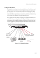
With 24 parallel bridging ports (i.e., 24 distinct collision domains), the
switch can collapse a complex network down into a single efficient bridged
node, increasing overall bandwidth and throughput.
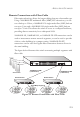
When up to eight switch units are stacked together, they form a single
“virtual” switch containing up to 200 ports. The whole stack can be
managed through the Master unit using a single IP address.
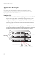
In the figure below, the 10BASE-T/100BASE-TX ports in a switch stack
are providing 100 Mbps connectivity for up to 72 segments. In addition,
the stack is also connecting several servers at 1000 Mbps.
Figure 2-2 Network Aggregation Plan
12
3
4
56
7
89
10
11 1 2
13
14
15 16
17
18 19
20
21 22
23
24
26
Console
25
1
2
11
12
13
14
23
24
Link/Act
PoE
25
26
Pwr
Diag
Stack
Mode
PoE/Link
RPS
12
3
4
56
7
89
10
11 1 2
13
14
15 16
17
18 19
20
21 22
23
24
26
Console
25
1
2
11
12
13
14
23
24
Link/Act
PoE
25
26
Pwr
Diag
Stack
Mode
PoE/Link
RPS
12
3
4
56
7
89
10
11 1 2
13
14
15 16
17
18 19
20
21 22
23
24
26
Console
25
1
2
11
12
13
14
23
24
Link/Act
PoE
25
26
Pwr
Diag
Stack
Mode
PoE/Link
RPS
Server Farm
10/100 Mbps Segments
...
...
24
24
24
Switch Units
Stacking Cable
2
4
2
4
T
x
R
x
2
4
2
4
T
x
R
x
2
4
2
4
T
x
R
x