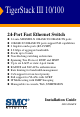
TigerStack III 10/100 24-Port Fast Ethernet Switch ◆ ◆ ◆ ◆ ◆ ◆ ◆ ◆ ◆ ◆ ◆ ◆ ◆ ◆ 24 auto-MDI/MDI-X 10BASE-T/100BASE-TX ports 10BASE-T/100BASE-TX ports support PoE capabilities 2 Gigabit combo ports (RJ-45/SFP) 8.
TigerStack III 10/100 Installation Guide From SMC’s Tiger line of feature-rich workgroup LAN solutions 38 Tesla Irvine, CA 92618 Phone: (949) 679-8000 June 2005 Pub.
Information furnished by SMC Networks, Inc. (SMC) is believed to be accurate and reliable. However, no responsibility is assumed by SMC for its use, nor for any infringements of patents or other rights of third parties which may result from its use. No license is granted by implication or otherwise under any patent or patent rights of SMC. SMC reserves the right to change specifications at any time without notice. Copyright © 2005 by SMC Networks, Inc. 38 Tesla Irvine, CA 92618 All rights reserved.
LIMITED WARRANTY Limited Warranty Statement: SMC Networks, Inc. (“SMC”) warrants its products to be free from defects in workmanship and materials, under normal use and service, for the applicable warranty term. All SMC products carry a standard 90-day limited warranty from the date of purchase from SMC or its Authorized Reseller. SMC may, at its own discretion, repair or replace any product not operating as warranted with a similar or functionally equivalent product, during the applicable warranty term.
LIMITED WARRANTY WARRANTIES EXCLUSIVE: IF AN SMC PRODUCT DOES NOT OPERATE AS WARRANTED ABOVE, CUSTOMER’S SOLE REMEDY SHALL BE REPAIR OR REPLACEMENT OF THE PRODUCT IN QUESTION, AT SMC’S OPTION. THE FOREGOING WARRANTIES AND REMEDIES ARE EXCLUSIVE AND ARE IN LIEU OF ALL OTHER WARRANTIES OR CONDITIONS, EXPRESS OR IMPLIED, EITHER IN FACT OR BY OPERATION OF LAW, STATUTORY OR OTHERWISE, INCLUDING WARRANTIES OR CONDITIONS OF MERCHANTABILITY AND FITNESS FOR A PARTICULAR PURPOSE.
COMPLIANCES FCC - Class A This equipment generates, uses, and can radiate radio frequency energy and, if not installed and used in accordance with the instruction manual, may cause interference to radio communications. It has been tested and found to comply with the limits for a Class A computing device pursuant to Subpart B of Part 15 of FCC Rules, which are designed to provide reasonable protection against such interference when operated in a commercial environment.
COMPLIANCES CE Mark Declaration of Conformance for EMI and Safety (EEC) This information technology equipment complies with the requirements of the Council Directive 89/336/EEC on the Approximation of the laws of the Member States relating to Electromagnetic Compatibility and 73/23/EEC for electrical equipment used within certain voltage limits and the Amendment Directive 93/68/EEC.
COMPLIANCES Australia AS/NZS 3548 (1995) - Class A SMC contact for products in Australia is: SMC Communications Pty. Ltd. Suite 18, 12 Tryon Road, Lindfield NSW2070, Phone: 61-2-94160437 Fax: 61-2-94160474 Safety Compliance Warning: Fiber Optic Port Safety CLASS I LASER DEVICE When using a fiber optic port, never look at the transmit laser while it is powered on. Also, never look directly at the fiber TX port and fiber cable ends when they are powered on.
COMPLIANCES • The socket outlet must be near to the unit and easily accessible. You can only remove power from the unit by disconnecting the power cord from the outlet. • This unit operates under SELV (Safety Extra Low Voltage) conditions according to IEC 60950. The conditions are only maintained if the equipment to which it is connected also operates under SELV conditions. France and Peru only This unit cannot be powered from IT† supplies.
COMPLIANCES • Le coupleur d’appareil (le connecteur du groupe et non pas la prise murale) doit respecter une configuration qui permet un branchement sur une entrée d’appareil EN 60320/IEC 320. • La prise secteur doit se trouver à proximité de l’appareil et son accès doit être facile. Vous ne pouvez mettre l’appareil hors circuit qu’en débranchant son cordon électrique au niveau de cette prise. • L’appareil fonctionne à une tension extrêmement basse de sécurité qui est conforme à la norme IEC 60950.
COMPLIANCES • Die Netzsteckdose muß in der Nähe des Geräts und leicht zugänglich sein. Die Stromversorgung des Geräts kann nur durch Herausziehen des Gerätenetzkabels aus der Netzsteckdose unterbrochen werden. • Der Betrieb dieses Geräts erfolgt unter den SELV-Bedingungen (Sicherheitskleinstspannung) gemäß IEC 60950. Diese Bedingungen sind nur gegeben, wenn auch die an das Gerät angeschlossenen Geräte unter SELV-Bedingungen betrieben werden. Stromkabel.
COMPLIANCES Warnings (in German) Warung: Dieses Produkt enthält keine Teile, die eine Wartung vom Benutzer benötigen. Warung: Installation und Deinstallation des Gerätes müssen von qualifiziertem Servicepersonal durchgeführt werden. Warung: Wenn das Gerät an eine Steckdose angeschlossen wird, muß der Masseanschluß am dreipoligen Netzstecker mit Schutzerde verbunden werden, um elektrische Gefahren zu vermeiden. Warung: Dieses Gerät nutzt Laser zur Signalübertragung über Glasfasern.
COMPLIANCES Audience This guide is for system administrators with a working knowledge of network management. You should be familiar with switching and networking concepts. Zielgruppe Dieser Anleitung ist fuer Systemadministratoren mit Erfahrung im Netzwerkmangement. Sie sollten mit Switch- und Netzwerkkonzepten vertraut sein.
TABLE OF CONTENTS 1 About the TigerStack III 10/100 . . . . . . . . . . . . . . . . . . .1-1 Overview . . . . . . . . . . . . . . . . . . . . . . . . . . . . . . . . . . . . . . . . . . . . . . . . . . . 1-1 Switch Architecture . . . . . . . . . . . . . . . . . . . . . . . . . . . . . . . . . . . . . 1-2 Power-over-Ethernet Capability . . . . . . . . . . . . . . . . . . . . . . . . . . . 1-2 Network Management Options . . . . . . . . . . . . . . . . . . . . . . . . . . . . 1-3 Description of Hardware . . .
TABLE OF CONTENTS Mounting . . . . . . . . . . . . . . . . . . . . . . . . . . . . . . . . . . . . . . . . . . . . . . . . . . . 3-4 Rack Mounting . . . . . . . . . . . . . . . . . . . . . . . . . . . . . . . . . . . . . . . . . 3-4 Desktop or Shelf Mounting . . . . . . . . . . . . . . . . . . . . . . . . . . . . . . . 3-7 Installing an SFP Transceiver . . . . . . . . . . . . . . . . . . . . . . . . . . . . . . . . . . . 3-8 Stacking Switches . . . . . . . . . . . . . . . . . . . . . . . . . . . . . . . . .
TABLE OF CONTENTS APPENDICES: A Troubleshooting . . . . . . . . . . . . . . . . . . . . . . . . . . . . . . . A-1 Diagnosing Switch Indicators . . . . . . . . . . . . . . . . . . . . . . . . . . . . . . . . . . .A-1 Diagnosing Power Problems with the LED Indicators . . . . . . . . .A-2 Power and Cooling Problems . . . . . . . . . . . . . . . . . . . . . . . . . . . . . . . . . . .A-2 Installation . . . . . . . . . . . . . . . . . . . . . . . . . . . . . . . . . . . . . . . . . . . . . . . . . .
TABLES Table 1-1 Table 1-2 Table 3-1 Table 4-1 Table 4-2 Table 4-3 Table 4-4 Table 4-5 Table 4-6 Table A-1 Table A-2 Table B-1 Table B-2 Table D-1 xii Port Status LED Indicators . . . . . . . . . . . . . . . . . . . . . . . . . . 1-5 System Status LED Indicators . . . . . . . . . . . . . . . . . . . . . . . . 1-7 Serial Cable Wiring . . . . . . . . . . . . . . . . . . . . . . . . . . . . . . . . 3-13 Maximum 1000BASE-T Gigabit Ethernet Cable Length . . .
FIGURES Figure 1-1 Figure 1-2 Figure 1-3 Figure 1-4 Figure 1-5 Figure 1-6 Figure 1-7 Figure 2-1 Figure 2-2 Figure 2-3 Figure 2-4 Figure 3-1 Figure 3-2 Figure 3-3 Figure 3-4 Figure 3-5 Figure 3-6 Figure 3-7 Figure 3-8 Figure 3-9 Figure 4-1 Figure 4-2 Figure 4-3 Figure B-1 Figure B-2 Figure B-3 Front and Rear Panels. . . . . . . . . . . . . . . . . . . . . . . . . . . . 1-2 Port LED Indicators . . . . . . . . . . . . . . . . . . . . . . . . . . . . . 1-5 System LED Indicators . . . . . . . . . . . . . . . .
FIGURES xiv
CHAPTER 1 ABOUT THE TIGERSTACK III 10/100 Overview SMC’s TigerStack III 10/100 SMC6826MPE is a 24-Port Fast Ethernet PoE Switch with 24 10BASE-T/100BASE-TX RJ-45 ports and two combination ports — 10/100/1000BASE-T ports that operate in combination with Small Form Factor Pluggable (SFP) transceiver slots*. An optional SFP stacking transceiver is available for connecting up to eight units to a 2 Gbps stack backplane. All the 10BASE-T/100BASE-TX ports on this switch support IEEE 802.3af standard (802.
ABOUT THE TIGERSTACK III 10/100 Combination RJ-45/SFP Ports Port Status Indicators (1-24) 1 2 3 4 5 6 7 1 8 9 10 11 13 12 11 14 15 16 17 18 19 20 13 21 22 23 24 23 25 26 Console Link/Act PoE 2 Stack Master Button System Indicators 12 Console Port 14 Pwr Diag 25 RPS 26 Stack Mode PoE /Link 24 Combination Port Status Indicators (25, 26) 10/100 Mbps RJ-45 Ports Mode PoE/Link Button RPS DC IN +12V 7.5A - 50V 7.5A 100-240V~ 50/60Hz 8.0-2.
OVERVIEW from the switch over the Ethernet cable without requiring its own separate power source. This capability gives network administrators centralized power control for devices such as IP phones and wireless access points, which translates into greater network availability. For each attached 802.3af-compliant device, the switch automatically senses the load and dynamically supplies the required power. The switch delivers power to a device using the two data wire pairs in UTP or STP.
ABOUT THE TIGERSTACK III 10/100 Description of Hardware 10/100BASE-T Ports The PoE switch base unit contains 24 10BASE-T/100BASE-TX RJ-45 ports. All ports support automatic MDI/MDI-X operation, so you can use straight-through cables for all network connections to PCs or servers, or to other switches or hubs. (See “10/100BASE-TX Pin Assignments” on page B-2.
DESCRIPTION OF HARDWARE Port and System Status LED Indicators The switch base unit also includes a display panel for key system and port indications that simplify installation and network troubleshooting. The LED indicators, which are located on the front panel for easy viewing, are shown below and described in the following tables. Port Status LEDs 1 2 3 4 5 6 7 8 9 1 2 Figure 1-2 Port LED Indicators The port status LED indicators have two display modes; Link and PoE.
ABOUT THE TIGERSTACK III 10/100 LED Condition Status 1~24 On Green (PoE Mode) Powered device is connected, but not drawing power. Flashing Green Powered device is receiving power. Flashing Amber Port has detected a power overload or short circuit and shut down the port’s power. On Amber The power budget for the switch has been exceeded and the port's power shut down. Alternate Green/ Amber Port power has been turned off by the administrator. Off No powered device is connected to the port.
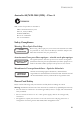
DESCRIPTION OF HARDWARE System Status LEDs Link/Act PWR PoE Diag 25 RPU 26 Stacking Mode PoE/Link Figure 1-3 System LED Indicators Table 1-2 System Status LED Indicators LED Condition Status PWR On Green Unit’s internal power supply is operating normally. Off Unit has no power connected. On Green System diagnostic test successfully completed. Flashing Green System diagnostic test is in progress. On Amber System diagnostic test has detected a fault.
ABOUT THE TIGERSTACK III 10/100 LED Condition Status Stacking On Green This switch is acting as the master unit in the stack. Flashing Green Initial state of stacking configuration to determine whether the switch will act as a master or slave unit. On Amber This switch is acting as a slave unit in the stack. Link/Act On Green LED display mode is Link/Act. PoE On Green LED display mode is PoE.
DESCRIPTION OF HARDWARE Mode PoE/Link Button The Mode PoE/Link button is located on the front panel. Mode Select Button Link/Act PWR PoE Diag 25 RPU 26 Stacking Mode PoE/Link Figure 1-5 Mode Selection The Mode PoE/Link button is used to toggle between the two port status LED display modes (see “Port Status LED Indicators” on page 1-5). Pressing this button changes from one display mode to the other. The default display mode is Link/Act mode.
ABOUT THE TIGERSTACK III 10/100 together using stacking cables (one stacking cable is included with each optional stacking transceiver). The push button on the switch’s front panel enables one switch in the stack to be selected as the master. (See “Stack Master Button” on page 1-8.) Power Supply Sockets There are two power sockets on the rear panel of the switch. The standard power socket is for the AC power cord. The socket labeled “RPS” is for the optional Redundant Power Supply. RPS DC IN +12V 7.
FEATURES AND BENEFITS • Unshielded (UTP) cable supported on all RJ-45 ports: Category 3 or better for 10 Mbps connections, Category 5 or better for 100 Mbps connections, and Category 5, 5e or 6 for 1000 Mbps connections • IEEE 802.3-2002 Ethernet, Fast Ethernet, Gigabit Ethernet, and flow control compliance ensures compatibility with standards-based hubs, network cards and switches from any vendor • Provides stacking capability via high-speed USB ports with 2 Gbps stacking bandwidth.
ABOUT THE TIGERSTACK III 10/100 Management • “At-a-glance” LED indicators for easy troubleshooting • Network management agent: - 1-12 Manages switch (or entire stack) in-band or out-of-band Supports console, Telnet, SSH, SNMP v1/v2c/v3, 4 RMON groups and web-based interface
CHAPTER 2 NETWORK PLANNING Introduction to Switching A network switch allows simultaneous transmission of multiple packets via non-crossbar switching. This means that it can partition a network more efficiently than bridges or routers. The switch has, therefore, been recognized as one of the most important building blocks for today’s networking technology.
NETWORK PLANNING Application Examples The switch is not only designed to segment your network, but also to provide a wide range of options in setting up network connections. Some typical applications are described below. Supplying PoE The switch is an excellent choice for supplying power to connected PoE devices such as web cameras, IP telephones or access points.
APPLICATION EXAMPLES Collapsed Backbone The switch is an excellent choice for mixed Ethernet, Fast Ethernet, and Gigabit Ethernet installations in which significant growth is expected in the near future. You can easily build on this basic configuration, adding direct full-duplex connections to workstations or servers. When the time comes for further expansion, just connect to another hub or switch via one of the switch’s Fast Ethernet or Gigabit Ethernet ports.
NETWORK PLANNING Network Aggregation Plan With 24 parallel bridging ports (i.e., 24 distinct collision domains), the switch can collapse a complex network down into a single efficient bridged node, increasing overall bandwidth and throughput. When up to eight switch units are stacked together, they form a single “virtual” switch containing up to 200 ports. The whole stack can be managed through the Master unit using a single IP address.
APPLICATION EXAMPLES Remote Connections with Fiber Cable Fiber optic technology allows for longer cabling than any other media type. Using a 1000BASE-SX multimode fiber (MMF) SFP transceiver, you can run a link up to 550 m, a 1000BASE-LX single-mode fiber (SMF) link can run up to 5 km, and a 1000BASE-LH single-mode fiber (SMF) link can run up to 70 km. This allows the switch to serve as a collapsed backbone, providing direct connectivity for a widespread LAN.
NETWORK PLANNING Making VLAN Connections This switch supports VLANs which can be used to organize any group of network nodes into separate broadcast domains. VLANs confine broadcast traffic to the originating group, and can eliminate broadcast storms in large networks. This provides a more secure and cleaner network environment. VLANs can be based on untagged port groups, or traffic can be explicitly tagged to identify the VLAN group to which it belongs.
APPLICATION NOTES Application Notes 1. Full-duplex operation only applies to point-to-point access (such as when a switch is attached to a workstation, server or another switch). When the switch is connected to a hub, both devices must operate in half-duplex mode. 2. Avoid using flow control on a port connected to a hub unless it is actually required to solve a problem. Otherwise back pressure jamming signals may degrade overall performance for the segment attached to the hub. 3.
NETWORK PLANNING 2-8
CHAPTER 3 INSTALLING THE SWITCH Selecting a Site Switch units can be mounted in a standard 19-inch equipment rack or on a flat surface. Be sure to follow the guidelines below when choosing a location. • The site should: - be at the center of all the devices you want to link and near a power outlet.
INSTALLING THE SWITCH • As with any equipment, using a filter or surge suppressor is recommended. Ethernet Cabling To ensure proper operation when installing the switch into a network, make sure that the current cables are suitable for 10BASE-T or 100BASE-TX operation.
EQUIPMENT CHECKLIST Equipment Checklist After unpacking this switch, check the contents to be that sure you have received all the components. Then, before beginning the installation, be sure that you have all other necessary installation equipment.
INSTALLING THE SWITCH Mounting This switch can be mounted in a standard 19-inch equipment rack or on a desktop or shelf. Mounting instructions for each type of site follow. Rack Mounting Before rack mounting the switch, pay particular attention to the following factors: • Temperature: Since the temperature within a rack assembly may be higher than the ambient room temperature, check that the rack-environment temperature is within the specified operating temperature range. (See page C-2.
MOUNTING 25 26 Link/A ct PoE 25 Pw r Diag RP S 26 Stac k M PoEode /Link Figure 3-2 Attaching the Brackets 2. Mount the device in the rack, using four rack-mounting screws (not provided). 25 26 Link/A ct PoE 25 26 Pwr Diag RPS Stac k Mo PoE de /Link Figure 3-3 Installing the Switch in a Rack 3. If installing a single switch only, turn to “Connecting to a Power Source” at the end of this chapter. 4. If installing multiple switches, mount them in the rack, one below the other, in any order.
INSTALLING THE SWITCH Montage (Rack Mounting Instructions - German) Switch-Einheiten können an ein standardmäßiges 19-Zoll Einrichtungsrack, einen Arbeitstisch oder ein Regal montiert werden. Folgend finden Sie die Montageanweisungen für jeden Positionstyp.
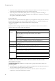
MOUNTING Desktop or Shelf Mounting 1. Attach the four adhesive feet to the bottom of the first switch. Mod PoE e /Link 26 25 Stac k RPS Diag PoE Pwr Link 24 /Act 26 25 14 23 12 23 21 19 17 15 13 2 13 24 22 20 18 16 14 11 11 9 7 Con sole 5 3 1 1 12 10 8 6 4 2 Figure 3-4 Attaching the Adhesive Feet 2. Set the device on a flat surface near an AC power source, making sure there are at least two inches of space on all sides for proper air flow. 3.
INSTALLING THE SWITCH Installing an SFP Transceiver 22 23 24 23 24 Link/A ct PoE 25 26 Pwr Diag RPS Stac k Mod PoE e /Link Figure 3-5 Installing an SFP Transceiver The SFP slots support the following optional SFP transceivers: • 1000BASE-SX • 1000BASE-LX • 1000BASE-LH To install an SFP transceiver, perform the following steps: 1. Consider your network and cabling requirements to select an appropriate SFP transceiver type. 2.
STACKING SWITCHES Stacking Switches The switch supports stacking up to eight units through an optional SFP stacking transceiver. Each stacking connection provides a 2 Gbps high-speed link using USB stacking cables. The stacking transceiver must be installed in the port 25 SFP slot. Each stacking transceiver has two connectors, Tx and Rx, for attaching stacking cables. Figure 3-7 shows how stacking cables are connected between switches in a stack.
INSTALLING THE SWITCH Connecting Switches in a Stack 13 13 14 15 Stack Master 16 17 18 19 20 21 22 23 24 23 14 25 26 24 Link /Act Tx PoE Rx 25 26 PWR Diag Stac king Mod PoE e /Link 13 13 14 15 Slave 16 17 18 19 20 21 22 23 24 23 14 25 26 24 Link /Act Tx PoE Rx 25 26 PWR Diag Stac king Mod PoE e /Link 13 13 14 15 Slave 16 17 18 19 20 21 22 23 24 23 14 25 26 24 Link /Act Tx PoE Rx 25 26 PWR Diag Stac king Mod PoE e /Link Figure 3-7 Connecting
STACKING SWITCHES 5. Complete the stack connections by plugging one end of a stack cable into the Tx port on the bottom unit and the other end into the Rx port on the top unit. 6. Select the Master unit in the stack by pressing the push button in on only one of the switches. Only one switch in the stack can operate as the Master, all other units operate in slave mode. If more than one switch in the stack is selected as Master, or if no switches are selected, the stack will not function.
INSTALLING THE SWITCH Connecting to a Power Source To connect a switch to a power source: 1. Insert the power cable plug directly into the AC socket located at the back of the switch. 100-240V~ 50/60Hz 8.0-2.0A Figure 3-8 Power Socket 2. Plug the other end of the cable into a grounded, 3-pin socket, AC power source. Note: For international use, you may need to change the AC line cord. You must use a line cord set that has been approved for the socket type in your country. 3.
CONNECTING TO THE CONSOLE PORT Connecting to the Console Port The DB-9 serial port on the switch’s front panel is used to connect to the switch for out-of-band console configuration. The command-line configuration program can be accessed from a terminal or a PC running a terminal emulation program. The pin assignments used to connect to the serial port are provided in the following table.
INSTALLING THE SWITCH 3-14 • Stop bit—One • Data bits—8 • Flow control—none
CHAPTER 4 MAKING NETWORK CONNECTIONS Connecting Network Devices The switch is designed to be connected to 10 or 100 Mbps network cards in PCs and servers, as well as to other switches and hubs. It may also be connected to remote devices using the optional 1000BASE-X, or 100BASE-FX SFP transceivers. If 802.3af-compliant PoE devices are connected to the switch’s 10/100 Mbps ports, the switch automatically supplies the required power.
MAKING NETWORK CONNECTIONS Power-over-Ethernet Connections The PoE switch automatically detects an 802.3af-compliant device by its authenticated PoE signature and senses its required load before turning on DC power to the port. This detection mechanism prevents damage to other network equipment that is not 802.3af compliant.
TWISTED-PAIR DEVICES Cabling Guidelines The RJ-45 ports on the switch support automatic MDI/MDI-X pinout configuration, so you can use standard straight-through twisted-pair cables to connect to any other network device (PCs, servers, switches, routers, or hubs). See Appendix B for further information on cabling. Caution: Do not plug a normal phone jack connector into an RJ-45 port. This will damage the switch. Use only twisted-pair cables with RJ-45 connectors that conform to FCC standards.
MAKING NETWORK CONNECTIONS 3. If the device is a network card and the switch is in the wiring closet, attach the other end of the cable segment to a modular wall outlet that is connected to the wiring closet. (See the section “Network Wiring Connections” on page 4-4) Otherwise, attach the other end to an available port on the switch. Make sure each twisted pair cable does not exceed 100 meters (328 ft) in length.
TWISTED-PAIR DEVICES Equipment Rack (side view) Switch 1 2 3 4 5 6 7 8 9 10 11 13 12 14 15 16 17 18 19 20 21 22 23 24 1 11 13 23 2 12 14 24 25 Console 26 Link/Act Pwr PoE Diag 25 RPS 26 Stack Mode PoE /Link Punch-Down Block Patch Panel Wall Figure 4-2 Network Wiring Connections 4-5
MAKING NETWORK CONNECTIONS Fiber Optic Devices An optional slide-in 1000BASE-SX, 1000BASE-LX, 1000BASE-LH, or 100BASE-FX SFP transceiver may be used for backbone or remote connections, or for connecting to a high-speed server. Each single-mode fiber optic port requires 9/125 micron single-mode fiber optic cabling with an LC connector at both ends. Each multimode fiber optic port requires 50/125 or 62.5/125 micron multimode fiber optic cabling with an LC connector at both ends.
CONNECTIVITY RULES 3. Connect one end of the cable to the LC port on the switch and the other end to the port on the other device. Since LC connectors are keyed, the cable can be attached in only one orientation. 13 13 14 15 16 17 18 19 20 21 22 23 24 23 14 25 26 24 LC fiber connector Link/A ct PoE 25 26 Pwr Diag RPS Stack Mo PoE de /Link Figure 4-3 Making Fiber Port Connections 4.
MAKING NETWORK CONNECTIONS 1000BASE-T Cable Requirements All Category 5 UTP cables that are used for 100BASE-TX connections should also work for 1000BASE-T, providing that all four wire pairs are connected. However, it is recommended that for all critical connections, or any new cable installations, Category 5e (enhanced Category 5) or Category 6 cable should be used. The Category 5e and 6 specifications include test parameters that are only recommendations for Category 5.
CABLE LABELING AND CONNECTION RECORDS Table 4-4 Maximum 1000BASE-LH Gigabit Ethernet Cable Length Fiber Size Fiber Bandwidth Maximum Cable Length Connector 9/125 micron single-mode fiber N/A 2 m - 70 km (7 ft 43.5 miles) LC 100 Mbps Fast Ethernet Collision Domain Table 4-5 Maximum Fast Ethernet Cable Lengths Type Cable Type 100BASE-TX Category 5 or better 100-ohm UTP or STP Max. Cable Length Connector 100 m (328 ft) RJ-45 100BASE-FX 50/125 or 62.5/125 micron core 2 km (1.
MAKING NETWORK CONNECTIONS To best manage the physical implementations of your network, follow these guidelines: 4-10 • Clearly label the opposing ends of each cable. • Using your building’s floor plans, draw a map of the location of all network-connected equipment. For each piece of equipment, identify the devices to which it is connected. • Note the length of each cable and the maximum cable length supported by the switch ports.
APPENDIX A TROUBLESHOOTING Diagnosing Switch Indicators Table A-1 Troubleshooting Chart Symptom Action PWR LED is Off • Internal power supply may be disconnected. Check connections between the switch, the power cord and the wall outlet. Diag LED is Amber • The system has detected a fault. Power cycle the switch to try and clear the condition. • If the condition does not clear, contact your dealer for assistance. Diag LED is Flashing Amber • Check that all stacking cables are properly connected.
TROUBLESHOOTING Diagnosing Power Problems with the LED Indicators The Power and RPU LED indicators work in combination to indicate power status as follows. Table A-2 Power/RPU LED Indicators Power LED RPU LED Status Green Green Internal power functioning normally; RPU is present. Green Amber Internal power functioning normally; RPU plugged in but faulty. Green Off Internal power functioning normally; RPU not plugged in. Amber Green Internal power faulty; RPU delivering power.
INSTALLATION Installation Verify that all system components have been properly installed. If one or more components appear to be malfunctioning (such as the power cord or network cabling), test them in an alternate environment where you are sure that all the other components are functioning properly. In-Band Access You can access the management agent in the switch from anywhere within the attached network using Telnet, a web browser, or other network management software tools.
TROUBLESHOOTING Stack Troubleshooting If a stack fails to initialize or function, first check the following items: • Check that all stacking cables are properly connected. • Check if any stacking cables appear damaged. • Check that only one Master Select button is pressed in. • Check that all switches in the stack are powered on. After checking all items, reboot all the switches in the stack. If the problem is still not resolved, contact your dealer for assistance.
APPENDIX B CABLES Twisted-Pair Cable and Pin Assignments For 10/100BASE-TX connections, the twisted-pair cable must have two pairs of wires. For 1000BASE-T connections the twisted-pair cable must have four pairs of wires. Each wire pair is identified by two different colors. For example, one wire might be green and the other, green with white stripes. Also, an RJ-45 connector must be attached to both ends of the cable. Caution: DO NOT plug a normal phone jack connector into any RJ-45 port.
CABLES 10/100BASE-TX Pin Assignments Use unshielded twisted-pair (UTP) or shielded twisted-pair (STP) cable for RJ-45 connections: 100-ohm Category 3 or better cable for 10 Mbps connections, or 100-ohm Category 5 or better cable for 100 Mbps connections. Also be sure that the length of any twisted-pair connection does not exceed 100 meters (328 feet). Data and PoE power are delivered on the standard two wire pairs (pins 1, 2, 3, and 6).
TWISTED-PAIR CABLE AND PIN ASSIGNMENTS Straight-Through Wiring If the twisted-pair cable is to join two ports and only one of the ports has an internal crossover (MDI-X), the two pairs of wires must be straight-through. (When auto-negotiation is enabled for any RJ-45 port on this switch, you can use either straight-through or crossover cable to connect to any device type.) You must connecting all four wire pairs as shown in the following diagram to support Gigabit Ethernet connections.
CABLES Crossover Wiring If the twisted-pair cable is to join two ports and either both ports are labeled with an “X” (MDI-X) or neither port is labeled with an “X” (MDI), a crossover must be implemented in the wiring. (When auto-negotiation is enabled for any RJ-45 port on this switch, you can use either straight-through or crossover cable to connect to any device type.) You must connect all four wire pairs as shown in the following diagram to support Gigabit Ethernet connections.
TWISTED-PAIR CABLE AND PIN ASSIGNMENTS 1000BASE-T Pin Assignments All 1000BASE-T ports support automatic MDI/MDI-X operation, so you can use straight-through cables for all network connections to PCs or servers, or to other switches or hubs. The table below shows the 1000BASE-T MDI-X and MDI port pinouts. These ports require that all four pairs of wires be connected. Note that for 1000BASE-T operation, all four pairs of wires are used for both transmit and receive.
CABLES Table B-2 1000BASE-T MDI-X and MDI Port Pinouts Pin 1 2 3 4 5 6 7 8 1000BASE-T MDI-X and MDI Port Pinouts MDI-X Signal Name MDI Signal Name Bi-directional Data Two Plus Bi-directional Data One Plus (BI_D2+) (BI_D1+) Bi-directional Data Two Minus Bi-directional Data One Minus (BI_D2-) (BI_D1-) Bi-directional Data One Plus Bi-directional Data Two Plus (BI_D1+) (BI_D2+) Bi-directional Data Four Plus Bi-directional Data Three Plus (BI_D4+) (BI_D3+) Bi-directional Data Four Minus Bi-directional Data Thre
FIBER STANDARDS Adjusting Existing Category 5 Cabling to Run 1000BASE-T If your existing Category 5 installation does not meet one of the test parameters for 1000BASE-T, there are basically three measures that can be applied to try to correct the problem: 1. Replace any Category 5 patch cables with high-performance Category 5e or Category 6 cables. 2. Reduce the number of connectors used in the link. 3. Reconnect some of the connectors in the link.
CABLES B-8
APPENDIX C SPECIFICATIONS Physical Characteristics Ports 24 10/100BASE-TX, with auto-negotiation 2 1000BASE-T/SFP combination ports Network Interface Ports 1-24: RJ-45 connector, auto MDI/X 10BASE-T: RJ-45 (100-ohm, UTP cable; Categories 3 or better) 100BASE-TX: RJ-45 (100-ohm, UTP cable; Category 5 or better) Ports 25, 26: RJ-45 connector, auto MDI/X 1000BASE-T: RJ-45 (100-ohm, UTP cable; Category 5, 5e, or 6) Buffer Architecture 8 Mbytes Aggregate Bandwidth 8.
SPECIFICATIONS Power Consumption 48 Watts (Switching system) 375 Watts (Power-over-Ethernet) Maximum Current 6.8 A @ 100 V AC 3.2 A @ 240 V AC LED Indicators System: PWR, Diag, RPS, Stacking Ports: Link/Act, PoE Weight 5.76 kg (12.70 lbs) Size 44.0 x 41.0 x 4.3 cm (17.32 x 16.14 x 1.69 in.
MANAGEMENT FEATURES Management Features In-Band Management Web, Telnet, SSH, or SNMP manager Out-of-Band Management RS-232 DB-9 console port Software Loading TFTP in-band, or XModem out-of-band Standards IEEE 802.3-2002 Ethernet, Fast Ethernet, Gigabit Ethernet, Full-duplex flow control IEEE 802.3af Power-over-Ethernet IEEE 802.3p priority tags IEEE 802.3ac VLAN tagging IEEE 802.1D Spanning Tree Protocol IEEE 802.1w Rapid Spanning Tree Protocol IEEE 802.
SPECIFICATIONS Compliances CE Mark Emissions Industry Canada Class A EN55022 (CISPR 22) Class A FCC Class A Industry Canada Class A EN55022 (CISPR 22) Class A EN 61000-3-2/3 VCCI Class A C-Tick - AS/NZS 3548 (1995) Class A Immunity EN 61000-4-2/3/4/5/6/8/11 Safety CSA/CUS (CSA60950-1 & UL60950-1) TÜV/GS (EN60950-1) CB (IEC60950-1) C-4
APPENDIX D ORDERING INFORMATION Table D-1 TigerStack III 10/100 Products and Accessories Product Number Description SMC6826MPE 24-port 10/100 stackable PoE switch with 2 Gigabit combination 1000BASE-T/SFP ports SMC6824S-P TigerStack III 10/100 Stacking Kit (includes 1 m stacking cable) SMCBGSLCX1 1-port 1000BASE-SX Small Form Pluggable (SFP) mini-GBIC transceiver SMCBGLLCX1 1-port 1000BASE-LX Small Form Pluggable (SFP) mini-GBIC transceiver SMCBGZLCX1 1-port 1000BASE-ZX Small Form Pluggable (SFP)
ORDERING INFORMATION D-2
GLOSSARY 10BASE-T IEEE 802.3 specification for 10 Mbps Ethernet over two pairs of Category 3, 4, or 5 UTP cable. 100BASE-FX IEEE 802.3u specification for Fast Ethernet over two strands of 50/125, 62.5/125 or 9/125 micron core fiber cable. 100BASE-TX IEEE 802.3u specification for 100 Mbps Ethernet over two pairs of Category 5 UTP cable. 1000BASE-LH Long-range Gigabit Ethernet over two strands of 9/125 micron core single-mode fiber cable. 1000BASE-LX IEEE 802.
GLOSSARY Auto-Negotiation Signalling method allowing each node to select its optimum operational mode (e.g., speed and duplex mode) based on the capabilities of the node to which it is connected. Bandwidth The difference between the highest and lowest frequencies available for network signals. Also synonymous with wire speed, the actual speed of the data transmission along the cable. Collision A condition in which packets transmitted over the cable interfere with each other.
GLOSSARY Fast Ethernet A 100 Mbps network communication system based on Ethernet and the CSMA/CD access method. Gigabit Ethernet A 1000 Mbps network communication system based on Ethernet and the CSMA/CD access method. Full Duplex Transmission method that allows two network devices to transmit and receive concurrently, effectively doubling the bandwidth of that link. IEEE Institute of Electrical and Electronic Engineers. IEEE 802.
GLOSSARY IEEE 802.3x Defines Ethernet frame start/stop requests and timers used for flow control on full-duplex links. (Now incorporated in IEEE 802.3-2002.) IEEE 802.3z Defines CSMA/CD access method and physical layer specifications for 1000BASE Gigabit Ethernet over fiber cabling. (Now incorporated in IEEE 802.3-2002.) LAN Segment Separate LAN or collision domain. LED Light emitting diode used for monitoring a device or network condition.
GLOSSARY Network Diameter Wire distance between two end stations in the same collision domain. Redundant Power Supply (RPS) A backup power supply unit that automatically takes over in case the primary power supply should fail. RJ-45 Connector A connector for twisted-pair wiring. Switched Ports Ports that are on separate collision domains or LAN segments.
GLOSSARY Glossary-6
INDEX Numerics 10 Mbps connectivity rules 4-6 100 Mbps connectivity rules 4-6 1000 Mbps connectivity rules 4-5 100BASE cable lengths 4-6 100BASE-TX ports 1-3 10BASE cable lengths 4-6 10BASE-T ports 1-3 100 Mbps 4-6 1000 Mbps 4-5 console port 1-2 pin assignments 3-10 contents of package 3-2 cooling problems A-2 cord sets, international 3-10 D A device connections 4-1 adhesive feet, attaching 3-6 air flow requirements 3-1 applications central wiring closet 2-3 collapsed backbone 2-2 remote connections wi
INDEX I O IEEE 802.
INDEX standards compliance C-2 IEEE C-3 status LEDs 1-3 surge suppressor, using 3-1 switch architecture 1-2 switching introduction to 2-1 method 1-2 T temperature within a rack 3-3 troubleshooting in-band access A-3 power and cooling problems A-2 switch indicators A-1 twisted-pair connections 4-1 W web-based management 1-2 Telnet A-3 Index-3
INDEX Index-4
FOR TECHNICAL SUPPORT, CALL: From U.S.A. and Canada (24 hours a day, 7 days a week) (800) SMC-4-YOU; (949) 679-8000; Fax: (949) 679-1481 From Europe (8:00 AM - 5:30 PM UK Time) 44 (0) 118 974 8700; Fax: 44 (0) 118 974 8701 INTERNET E-mail addresses: techsupport@smc.com european.techsupport@smc-europe.com support@smc-asia.com Driver updates: http://www.smc.com/index.cfm?action=tech_support_drivers_downloads World Wide Web: http://www.smc.com http://www.smc-europe.com http://www.smc-asia.