
Switch User Manual

T
WISTED
-P
AIR
D
EVICES
4-3
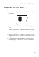
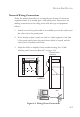
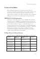
Network Wiring Connections
Today, the punch-down block is an integral part of many of the newer
equipment racks. It is actually part of the patch panel. Instructions for
making connections in the wiring closet with this type of equipment
follows.
1. Attach one end of a patch cable to an available port on the switch, and
the other end to the patch panel.
2. If not already in place, attach one end of a cable segment to the back
of the patch panel where the punch-down block is located, and the
other end to a modular wall outlet.
3. Label the cables to simplify future troubleshooting. See “Cable
Labeling and Connection Records” on page 4-10.
Figure 4-2 Wiring Closet Connections
Equipment Rack
(side view)
Network Switch
Patch Panel
Punch-Down Block
Wall
witch 10/100
6724L 3
E
S
4
5
2
4
C
CheetahSwitchW
orkgroup-4549
ES4549
45
46
47
48
StackMaster
StackLink
Power
RPU
Diag
Module
StackID
Console
12
3
4
5
6
7
89
10
11
12
13
14
15
16
17
18
19
20
21
22
23 24
25
26
27
28 29 30
31 32 33
34
35 36
37
38
39
40 41
42
43
44 45 46 47 48
14
13
16
15
18
17
20
19
22
21
24
23
26
25
28
27
30
29
32
31
34
33
36
35
38
37
40
39
42
41
44
43
46
45
48
47
2
1
4
3
6
5
8
7
10
9
12
11
Master
Select
Master
Select