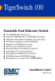
TigerSwitch 100 Stackable Fast Ethernet Switch ◆ ◆ ◆ ◆ ◆ ◆ ◆ ◆ ◆ ◆ ◆ 24 100BASE-FX VF-45 ports Optional 100BASE-FX or 1000BASE-X modules Optional stack module for linking up to four units 8.8 Gbps of aggregate switch bandwidth Support for redundant power unit Up to five port trunks per switch Port mirroring for non-intrusive analysis QoS support for two-level priority Full support for IEEE 802.
TigerSwitch 100 Installation Guide From SMC’s Tiger line of feature-rich workgroup LAN solutions 6 Hughes Irvine, CA 92618 Phone: (949) 707-2400 June 2001 Pub. # F2.
Information furnished by SMC Networks, Inc. (SMC) is believed to be accurate and reliable. However, no responsibility is assumed by SMC for its use, nor for any infringements of patents or other rights of third parties which may result from its use. No license is granted by implication or otherwise under any patent or patent rights of SMC. SMC reserves the right to change specifications at any time without notice. Copyright © 2001 by SMC Networks, Inc. 6 Hughes Irvine, CA 92618 All rights reserved.
LIMITED WARRANTY Limited Warranty Limited Warranty Statement: SMC Networks, Inc. (“SMC”) warrants its products to be free from defects in workmanship and materials, under normal use and service, for the applicable warranty term. All SMC products carry a standard 90-day limited warranty from the date of purchase from SMC or its Authorized Reseller.
LIMITED WARRANTY OF ALL OTHER WARRANTIES OR CONDITIONS, EXPRESS OR IMPLIED, EITHER IN FACT OR BY OPERATION OF LAW, STATUTORY OR OTHERWISE, INCLUDING WARRANTIES OR CONDITIONS OF MERCHANTABILITY AND FITNESS FOR A PARTICULAR PURPOSE. SMC NEITHER ASSUMES NOR AUTHORIZES ANY OTHER PERSON TO ASSUME FOR IT ANY OTHER LIABILITY IN CONNECTION WITH THE SALE, INSTALLATION, MAINTENANCE OR USE OF ITS PRODUCTS.
COMPLIANCES FCC - Class A This equipment generates, uses, and can radiate radio frequency energy and, if not installed and used in accordance with the instruction manual, may cause interference to radio communications. It has been tested and found to comply with the limits for a Class A computing device pursuant to Subpart B of Part 15 of FCC Rules, which are designed to provide reasonable protection against such interference when operated in a commercial environment.
COMPLIANCES Industry Canada - Class A This digital apparatus does not exceed the Class A limits for radio noise emissions from digital apparatus as set out in the interference-causing equipment standard entitled “Digital Apparatus,” ICES-003 of the Department of Communications.
COMPLIANCES Safety Compliance Warning: Fiber Optic Port Safety CLASS I LASER DEVICE When using a fiber optic port, never look at the transmit laser while it is powered on. Also, never look directly at the fiber TX port and fiber cable ends when they are powered on. Avertissment: Ports pour fibres optiques - sécurité sur le plan optique DISPOSITIF LASER DE CLASSE I Ne regardez jamais le laser tant qu'il est sous tension.
COMPLIANCES Wichtige Sicherheitshinweise (Germany) 1. Bitte lesen Sie diese Hinweise sorgfältig durch. 2. Heben Sie diese Anleitung für den späteren Gebrauch auf. 3. Vor jedem Reinigen ist das Gerät vom Stromnetz zu trennen. Verwenden Sie keine Flüssigoder Aerosolreiniger. Am besten eignet sich ein angefeuchtetes Tuch zur Reinigung. 4. Die Netzanschlu ßsteckdose soll nahe dem Gerät angebracht und leicht zugänglich sein. 5. Das Gerät ist vor Feuchtigkeit zu schützen. 6.
TABLE 1 OF CONTENTS About the TigerSwitch 100 . . . . . . . . . . . . . . . . . 1-1 Overview . . . . . . . . . . . . . . . . . . . . . . . . . . . . . . . . . Switch Architecture . . . . . . . . . . . . . . . . . . . . . . Management Options . . . . . . . . . . . . . . . . . . . . Description of Hardware . . . . . . . . . . . . . . . . . . . . . . 100BASE-FX VF-45 Ports . . . . . . . . . . . . . . . . . . Status LEDs . . . . . . . . . . . . . . . . . . . . . . . . . . . Network Management Module . . . .
TABLE OF CONTENTS Desktop or Shelf Mounting . . . . . . . . . . . . . Installing an Optional Module into the Switch Stacking . . . . . . . . . . . . . . . . . . . . . . . . . . . Connecting to a Power Source . . . . . . . . . . . . . . . 4 .. . .. .. . . . . . . . . . . . . . . . . . . . . . . . . . . . . . . . . . . . . . . . . . . . . . . . . . . . . . . . . . . . . . . . . . . . . . . . . 3-5 3-6 3-7 3-9 . . . . . . . . . . . . . . . . . . . . . . . . . . . . . . . . . . . . .
TABLE OF CONTENTS Standards . . . . . . . . . . . . . . . . . . . . . Compliances . . . . . . . . . . . . . . . . . . . Warranty . . . . . . . . . . . . . . . . . . . . . . Slide-in Module . . . . . . . . . . . . . . . . . 100BASE-FX Extender Module . 1000BASE-SX Extender Module . 1000BASE-LX Extender Module . 1000BASE-T Extender Module . . Agent Module . . . . . . . . . . . . . Stack Module . . . . . . . . . . . . . . D ... ... ... ... ... ... ... ... ... ... ... ... ... ... ... ... ... ... ... ... . .
TABLE OF CONTENTS viii
CHAPTER 1 ABOUT THE TIGERSWITCH 100 Overview SMC’s TigerSwitch™ 100 is a stackable switch with 24 100BASE-FX VF-45 ports, plus two slots for optional slide-in 100BASE-FX or 1000BASE-X modules. One of these slots can also be used for an optional stacking module that allows you attach up to four switches to a 9.6 Gbps high-speed backplane. There is also an SNMP-based Network Management Module installed in the rear panel.
ABOUT THE TIGERSWITCH 100 100BASE-FX Multimode Fiber Module 100BASE-FX Single-mode Fiber Module 100Base-FX-SC Extender Module 100Base-FX Singlemode SC Module SMC6900FSC SMC6900FSSC 1000BASE-SX Gigabit Module 1000BASE-LX Gigabit Module SMC6900G 1000BASE-T Gigabit Module SMC6900GLSC Stack Module SMC6900GT Figure 1-3. Optional Modules Switch Architecture The TigerSwitch employs a high-speed switching fabric.
ABOUT THE TIGERSWITCH 100 Management Options This switch contains a comprehensive array of LEDs for “at-a-glance” monitoring of network and port status. It also includes a Network Management Module that allows the entire stack to be managed in-band via SNMP or RMON (Groups 1, 2, 3 and 9) protocols, with a Web browser, or remotely via Telnet. The switch also provides a serial port on the rear panel for out-of-band management.
ABOUT THE TIGERSWITCH 100 Status LEDs The LEDs, which are located on the front panel for easy viewing, are shown below and described in the following table. Status Activity 1 U Figure 1-4. Port and System LEDs Port and System Status LEDs LED Condition Status Power On Switch is receiving power. RPU On Redundant power is on, and the RPU is in backup or active mode. Off Redundant power is off or has failed. On Agent is operational. On Port has established a valid network connection.
ABOUT THE TIGERSWITCH 100 Port and System Status LEDs LED Condition Status Status On A module is installed in this slot. Activity On Traffic is passing through the module. Module Ports Network Management Module Network Management Module SMC6924VFNMM RS-232 Figure 1-5. Network Management Module This switch includes a Network Management Module on the rear panel. This module can manage the switch and the attached stack.
ABOUT THE TIGERSWITCH 100 caused by port saturation. And broadcast storm control prevents broadcast traffic storms from engulfing the network. Some of this switch’s advanced features are described below. For a detailed description, refer to the Management Guide. Spanning Tree Protocol The TigerSwitch 100 supports IEEE 802.1D Spanning Tree Protocol. This protocol adds a level of fault tolerance by allowing two or more redundant connections to be created between a pair of LAN segments.
ABOUT THE TIGERSWITCH 100 • Provides data security by restricting all traffic to the originating VLAN, except where a connection has been configured between separate VLANs using a router or Layer 3 switch. Multicast Switching Specific multicast traffic can be assigned to its own VLAN to ensure that it does not interfere with normal network traffic and to guarantee real-time delivery by setting the required priority level for the designated VLAN.
ABOUT THE TIGERSWITCH 100 Optional 100BASE-FX Module (SMC6900FSSC) 100Base-FX Singlemode SC Module SMC6900FSSC Figure 1-7. 1-Port 100BASE-FX Single-Mode Fiber Module Using single-mode fiber optic cable, the 100BASE-FX port can be connected to a remote site up to 10 km (6.21 mi.) away. This port operates only at 100 Mbps, full duplex. Optional 1000BASE-SX Module (SMC6900G) SMC6900G Figure 1-8.
ABOUT THE TIGERSWITCH 100 9/125 micron single-mode fiber cable. The 1000BASE-LX Gigabit module operates at 1 Gbps, with support for auto-negotiation of duplex mode and flow control. Optional 1000BASE-T Module (SMC6900GT) SMC6900GT Figure 1-10. Single-Port 1000BASE-T Gigabit Module SMC6900GT contains one 1000BASE-T RJ-45 port that can support a link of up to 100 m (328 ft) using Category 5 or 5e twisted-pair cable.
ABOUT THE TIGERSWITCH 100 Power Supply Receptacles There are two power receptacles on the rear panel of the switch. The standard power receptacle is for the AC power cord. The receptacle labeled “DC Input” is for the optional Redundant Power Unit (RPU). Figure 1-12.
ABOUT THE TIGERSWITCH 100 Features and Benefits Connectivity ◆ 24 multimode fiber VF-45 ports that offer a cost-effective solution for fiber-to-the-desktop applications ◆ Each VF-45 port operates at 100 Mbps in half- or full-duplex mode (configured manually) ◆ 62.5/125 micron and 50/125 micron multimode fiber cable supported on all VF-45 ports ◆ 802.
ABOUT THE TIGERSWITCH 100 ◆ Optional 1000BASE-T Gigabit module that supports a connection of up to 100 meters using Category 5 or 5e UTP or STP cable, and operates at 1 Gbps, 100 Mbps, or 10 Mbps, half or full duplex, with auto-negotiation for speed, duplex mode and flow control ◆ Optional Stack modules that can connect up to four switches (104 ports) to the stack’s 9.6 Gbps backplane Performance ◆ Transparent bridging ◆ Aggregate bandwidth up to 8.
ABOUT THE TIGERSWITCH 100 • Spanning Tree Protocol for redundant network connections • VLAN support for 256 groups, port-based or with IEEE 802.
ABOUT THE TIGERSWITCH 100 1-14
CHAPTER 2 NETWORK PLANNING Introduction to Switching A network switch allows simultaneous transmission of multiple packets via non-crossbar switching. This means that it can partition a network more efficiently than bridges or routers. The switch has, therefore, been recognized as one of the most important building blocks for today’s networking technology.
NETWORK PLANNING Sample Applications The TigerSwitch 100 is not only designed to segment your network, but also to provide a wide range of options in setting up network connections. Some typical applications are described below. Collapsed Backbone The TigerSwitch 100 is an excellent choice for mixed Fast Ethernet installations where significant growth is expected in the near future. You can easily build on this basic configuration, adding direct full-duplex connections to workstations or servers.
NETWORK PLANNING Central Wiring Closet With up to 104 ports in a stack (i.e., 104 distinct segments), the TigerSwitch 100 can collapse a complex network down into a single efficient bridged node, increasing overall bandwidth and throughput. In the figure below, the VF-45 ports on the TigerSwitch stack are providing 100 Mbps connectivity for up to 96 end nodes. In addition, the switch is also connecting servers at 2 Gbps.
NETWORK PLANNING Remote Connections with Fiber Cable Fiber optic technology allows for longer cabling than any other media type (up to 10 kilometers for 100 Mbps single-mode fiber at full duplex, or up to 5 kilometers for 1 Gbps fiber). The TigerSwitch can serve as a collapsed backbone, providing direct connectivity for a widespread LAN. The 100 Mbps single-mode fiber module can be used to interconnect remote Fast Ethernet segments.
NETWORK PLANNING Making VLAN Connections VLANs can be based on port groups, or each data frame can be explicitly tagged to identify the VLAN group it belongs to. When using port-based VLANs, ports can either be assigned to any number of groups. Port-based VLANs are suitable for small networks. A single switch can be easily configured to support several VLAN groups for various organizational entities (such as Finance and Marketing).
NETWORK PLANNING Connectivity Rules When adding hubs (repeaters) to your network, please follow the connectivity rules listed below for Ethernet, Fast Ethernet, or Gigabit Ethernet. However, note that because switches break up the path for connected devices into separate collision domains, you should not include the switch or connected cabling in your calculations for cascade length involving other devices.
NETWORK PLANNING 100 Mbps Fast Ethernet Collision Domain Maximum 100BASE-FX Fiber Optic Cable Distance 100BASE-FX 50/125 or 62.5/125 micron core multimode fiber (MMF) Full duplex 100BASE-FX 2 km (1.24 miles) SC or ST 9/125 9 micron core single-mode fiber (SMF) Full duplex 10 km (6.
NETWORK PLANNING Maximum Fast Ethernet Cable Distance Cable Type 2-8 Connecting Max. Distance Twisted Pair Any two devices 100 m (328 ft.) Fiber Switch to switch, server or PC Half duplex 412 m (1,351.4 ft.) Full duplex 2 km (1.24 mi.
NETWORK PLANNING Application Notes 1. Full-duplex operation only applies to point-to-point access (such as when a switch is attached to a workstation, server or another switch). When the switch is connected to a hub, both devices must operate in half-duplex mode. 2. When a switch is connected to a hub or any kind of shared media, remember to turn off back pressure to prevent the attached port from being frequently partitioned due to the jamming packets. 3.
NETWORK PLANNING 2-10
INSTALLING CHAPTER 3 THE SWITCH Selecting a Site TigerSwitch 100 units can be mounted in a standard 19-inch equipment rack or on a flat surface. Be sure to follow the guidelines below when choosing a location. ◆ The site should: • be at the center of all the devices you want to link and near a power outlet.
INSTALLING THE SWITCH Equipment Checklist After unpacking the TigerSwitch 100, check the contents to be sure you have received all the components. Then, before beginning the installation, be sure you have all other necessary installation equipment.
INSTALLING THE SWITCH Mounting A TigerSwitch 100 unit can be mounted in a standard 19-inch equipment rack or on a desktop or shelf. Mounting instructions for each type of site follow. Installing Optional Modules: Before mounting the switch, be sure you install any optional modules. If you have purchased an optional slide-in 100BASE-FX or 1000BASE-X media expansion module, or Stack Module, install these modules now, following the instructions included with the package.
INSTALLING THE SWITCH To rack-mount devices: 1. Attach the brackets to the device using the screws provided in the Bracket Mounting Kit. Status Activ ity 1 Figure 3-1. Attaching the Brackets 2. Mount the device in the rack, using four rack-mounting screws (not provided). Status Activi ty 1 Figure 3-2.
INSTALLING THE SWITCH 3. If installing a single switch only, turn to “Connecting to a Power Source” at the end of this chapter. 4. If installing multiple switches, mount them in the rack, one below the other, in any order. 5. If also installing RPUs, mount them in the rack below the other devices. Desktop or Shelf Mounting 1. Attach the four adhesive feet to the bottom of the first switch. 1 Status Activi ty Figure 3-3. Attaching the Adhesive Feet 2.
INSTALLING THE SWITCH Installing an Optional Module into the Switch Optional modules are available for media expansion, stacking and management. These modules can be installed into the modular slots on the rear panel of the switch. The Network Management Module must be installed in the upper slot, and the Stack Module in the lower-left slot. The media expansion modules can be installed in either of the two lower slots. Caution: DO NOT install slide-in modules with the switch powered on.
INSTALLING THE SWITCH 100B SMC6 ase- 900F FX-S C Ex tend er M odul e SC Figure 3-4. Installing a Module 6. If you are sure the module is properly mated with the connector, tighten the retainer screws by hand to secure the module in the slot. 7. Connect power to the switch. Stacking A stack may have as many as four switches. Note: A stacking cable is included with the Stack Module. Caution: DO NOT stack TigerSwitch 100 units with other devices. Doing so may damage the switch.
INSTALLING THE SWITCH 3. Repeat this step until all the devices have been connected. 4. Turn to the next section, “Connecting to a Power Source.” 24VF Figure 3-5.
INSTALLING THE SWITCH Connecting to a Power Source To connect a device to a power source: Note: It is recommended that the switches be stacked before being connected to a power source. However, a device can be added to the top or bottom of a stack that is on and operating without first powering down the stack. Be sure to stack the new device before connecting it to a power source. All switches in a stack must be powered on to allow traffic to pass across the stack’s backplane.
INSTALLING THE SWITCH 3. Check the front-panel LEDs as the device is powered on to be sure the Power LED is lit. If not, check that the power cable is correctly plugged in. The Mgmt LED on the unit with the Network Management Module installed will be lit. 4. If you have a purchased Redundant Power Unit, connect it to the device and to an AC power source now, following the instructions included with the package.
CHAPTER 4 MAKING NETWORK CONNECTIONS Connecting Network Devices The TigerSwitch 100 is designed to interconnect multiple segments (or collision domains). It may be connected to 100 Mbps network cards in PCs and servers, as well as to Fast Ethernet hubs, switches or routers. It may also be connected to remote devices using the optional 100BASE-FX or 1000BASE-X modules. Note: Before connecting cables, you may want to first configure the Spanning Tree Protocol to avoid network loops.
MAKING NETWORK CONNECTIONS VF-45 Fiber Connections Each device requires a 62.5/125 micron or 50/125 micron multimode fiber optic cable with VF-45 connectors at both ends. 1. Remove and keep the VF-45 port’s plastic cover. When not connected to a fiber cable, the cover should be replaced to protect the optics. 2. Check that the fiber terminators are clean. You can clean the cable plugs using an appropriate VF-45 cleaning kit.
MAKING NETWORK CONNECTIONS SC Fiber Connections An optional slide-in 100BASE-FX module may be used for backbone and long distance connections. A 1000BASE-X module may also be used for a backbone connection between switches, or for connecting to a high-speed server. Each multimode fiber optic port requires 50/125 or 62.5/125 micron multimode fiber optic cabling with an SC connector at both ends. If you need to connect to a device with 62.
MAKING NETWORK CONNECTIONS 3. Connect one end of the cable to the SC port on the switch and the other end to the SC port on the other device. Since SC connectors are keyed, the cable can be attached in only one orientation. Figure 4-1. Making SC Port Connections 4. As a connection is made, check the Activity LED on the switch’s front panel for the corresponding module to be sure that the connection is valid.
MAKING NETWORK CONNECTIONS 1000BASE-T Twisted-Pair Connections A 1000BASE-T connection requires a shielded or unshielded twisted-pair (STP or UTP) cable with RJ-45 connectors at both ends. For all connections, Category 5 or 5e (recommended) cable is required with all four wire pairs connected. You should also test the cable installation for IEEE 802.3ab compliance. See “1000BASE-T Cable Requirements” on page B-4.
MAKING NETWORK CONNECTIONS Figure 4-2. Making Twisted-Pair Connections 2. If the device is a network card and the TigerSwitch is in the wiring closet, attach the other end of the cable segment to a modular wall outlet that is connected to the wiring closet (see “Wiring Closet Connections” on the next page). Otherwise, attach the other end to the port on the 1000BASE-T module. Make sure the twisted pair cable does not exceed 100 meters (328 ft.) in length.
MAKING NETWORK CONNECTIONS Wiring Closet Connections Today, the punch-down block is an integral part of many of the newer equipment racks. It is actually part of the patch panel. Instructions for making connections in the wiring closet with this type of equipment follows. 1. Attach one end of a patch cable to the port on the 1000BASE-T module, and the other end to the patch panel. 2.
MAKING NETWORK CONNECTIONS 4-8
APPENDIX A TROUBLESHOOTING Diagnosing Switch Indicators Troubleshooting Chart Symptom Action Power LED is Off • Internal or redundant power supply has failed or is disconnected. • Check connections between the switch, the power cord, the wall outlet, and the RPU if you are using one. • If the switch is installed in a rack, check the connections to the punch-down block and patch panel. • Contact SMC Technical Support.
TROUBLESHOOTING Power and Cooling Problems If the power indicator does not turn on when the power cord is plugged in, you may have a problem with the power outlet, power cord, or internal power supply. However, if the unit powers off after running for a while, check for loose power connections, power losses or surges at the power outlet, and verify that the fans on the unit are unobstructed and running prior to shutdown.
TROUBLESHOOTING Note: You can configure the management agent to accept from one to four simultaneous Telnet sessions. If the maximum number of sessions already exists, an additional Telnet connection will not be able to log into the system.
TROUBLESHOOTING A-4
APPENDIX B CABLES Specifications Cable Types and Specifications Cable Type 100BASE-FX 50/125 or 62.5/125 micron core multimode fiber (MMF) 100BASE-FX Max. Length Connector Half Duplex 412 m (1,351 ft) Full duplex 2 km (1.24 miles) VF-45, SC or ST VF-45 9/125 9 micron core single-mode fiber (SMF) Full duplex 10 km (6.21 miles) SC or ST 1000BASE-SX 50/125 or 62.
CABLES 1000BASE-LX Fiber Specifications Fiber Diameter Fiber Bandwidth Cable Length Range 62.5/125 micron MMF 160 MHz/km 2-50 m (7-1805 ft) 50/125 micron MMF 400 MHz/km 2-550 m (7-1805 ft) 500 MHz/km 2-550 m (7-1805 ft) N/A 2 m - 5 km (7-16,404 ft) 9/125 micron SMF Note: If you need to connect to a device with 62.5/125 micron cable that has ST-type connectors, SMC provides an optional SC-ST Converter (Part Number: 99-012034-091).
CABLES RJ-45 Port and Cable Assignments CAUTION: DO NOT plug a phone jack connector into any RJ-45 port. Use only twisted-pair cables with RJ-45 connectors that conform with FCC standards. The RJ-45 port on the SMC6900GT module supports 1000, 100, and 10 Mbps Ethernet operation, with auto-negotiation of speed, duplex mode, and flow control.
CABLES The table below shows the 1000BASE-T MDI and MDI-X port pinouts. These ports require that all four pairs of wires be connected. Note that for 1000BASE-T operation, all four pairs of wires are used for both transmit and receive.
CABLES cable testing information is specified in the ANSI/TIA/EIA-TSB-67 standard. Additionally, cables must also pass test parameters for Return Loss and Equal-Level Far-End Crosstalk (ELFEXT). These tests are specified in the ANSI/TIA/EIA-TSB-95 Bulletin, “The Additional Transmission Performance Guidelines for 100 Ohm 4-Pair Category 5 Cabling.” Note that when testing your cable installation, be sure to include all patch cables between switches and end devices.
CABLES Console Port Pin Assignments The DB-9 serial port on the switch’s rear panel is used to connect to the switch for out-of-band console configuration. The on-board menu-driven configuration program can be accessed from a terminal, a PC running a terminal emulation program, or from a remote location via a modem connection. The pin assignments used to connect to the serial port are provided in the following tables. Figure B-1.
CABLES Console Port to 9-Pin COM Port on PC Switch’s 9-Pin Serial Port 1 DCD 2 RXD 3 TXD 4 DTR 5 SGND 6 DSR 7 RTS 8 CTS 9 RI CCITT Signal ----------<----------------------------------------------------------<------------------- PC’s 9-Pin COM Port DCD -----------TXD -----------RXD ----------> DSR ----------> SGND ---------DTR -----------CTS -----------> RTS ------------RI --------------- 1 3 2 6 5 4 8 7 9 Console Port to 25-Pin DCE Port on Modem Switch’s 9-Pin Serial Port 1 2 3 4 5 6 7 8 9 CCITT Signa
CABLES B-8
APPENDIX C SPECIFICATIONS Physical Characteristics Ports 24 100BASE-FX fiber 1 slot for an optional media expansion module 1 slot for an optional media expansion module or stacking module Network Interface 100BASE-FX: VF-45 connector Multimode fiber cable; 62.5/125 or 50/125 microns Stack Interface Connects up to 4 units 4.8 Gbps, full duplex, uplink/downlink ports 9.6 Gbps stack backplane bandwidth Buffer Architecture 32 Kbytes per 100 Mbps ports 2 Mbytes per 1000 Mbps ports Aggregate Bandwidth 8.
SPECIFICATIONS Weight 10.63 lbs (4.82 kg) Size 17.37 x 11.22 x 2.53 in (44.0 x 28.5 x 6.4 cm) Temperature Operating: 32 to 122°F (0 to 50°C) Storage: -40 to 158°F (-40 to 70°C) Humidity Operating: 5% to 95% AC Input 100 to 240 V, 50 to 60 Hz Power Supply Internal, auto-ranging transformer: 100 to 240 VAC, 50 to 60 Hz Redundant DC input Power Consumption 70 Watts maximum Heat Dissipation 273 BTU/hr maximum Maximum Current 0.80A @ 110VAC 0.
SPECIFICATIONS Switch Features Spanning Tree Protocol Forwarding Mode Store-and-forward Throughput Wire speed Flow Control Full Duplex: IEEE 802.3x Half Duplex: Back pressure Broadcast Storm Control Configurable threshold on a per-port basis. VLAN Support Up to 256 groups; port-based or with 802.
SPECIFICATIONS Management Features In-Band Management Telnet, Web-based HTTP, or SNMP manager (EliteView Network Management software provided for free) Out-of-Band Management RS-232 DB-9 console port Software Loading TFTP or Web (HTTP) in-band or XModem out-of-band MIB Support MIB II (RFC 1213), Bridge MIB (RFC 1493), Ethernet-Like MIB (RFC 1643), RMON MIB (RFC 1757), SMC’s private MIB RMON Support Groups 1, 2, 3, 9 (Statistics, History, Alarm, Event) Additional Features Port Trunks Port Security Port Mirr
SPECIFICATIONS Standards IEEE 802.3u Fast Ethernet IEEE 802.3z Gigabit Ethernet IEEE 802.1D Spanning Tree Protocol and traffic priorities IEEE 802.1Q VLAN Bridge Management IEEE 802.
SPECIFICATIONS Slide-in Module 100BASE-FX Extender Module Model SMC6900FSC, SMC6900FST, SMC6900FSSC Ports SMC6900FSC, SMC6900FST: 2 100BASE-FX multimode SMC6900FSSC: 1 100BASE-FX single-mode Network Interface SMC6900FSC, SMC6900FST: 50/125 or 62.5/125 micron multimode fiber cable (SMC6900FST includes SC-ST Converter) SMC6900FSSC: 9/125 micron single-mode fiber cable Communication Mode Full duplex Communication Rate 100 Mbps Standards IEEE 802.
SPECIFICATIONS Communication Mode Full and half duplex, auto-negotiation Communication Rate 1000 Mbps Standards IEEE 802.3z Gigabit Ethernet 1000BASE-LX Extender Module Model SMC6900GLSC Ports 1 1000BASE-LX Network Interface SC connector, 9/125 micron single-mode fiber cable Communication Mode Full and half duplex, auto-negotiation Communication Rate 1000 Mbps Standards IEEE 802.
SPECIFICATIONS Communication Mode Full and half duplex, auto-negotiation Communication Rate 1000, 100, and 10 Mbps Standards IEEE 802.3ab Gigabit Ethernet Agent Module Model SMC6924VFNMM Ports 1 RS-232 serial port Connector Interface Standard straight-through wired RS-232 cable Standards IEEE 802.3u Fast Ethernet ISO/IEC 8802-3 Stack Module Model SMC6900S Ports 4.8 Gbps uplink/downlink ports Connector Interface 68-pin SCSI connector, copper cable Standards IEEE 802.
ORDERING APPENDIX D INFORMATION TigerSwitch 100 Products and Accessories Product Number Description SMC6924VF 24-port Fast Ethernet switch with two media expansion slots SMC6924VFNMM Network Management Module with one RS-232 serial port SMC6900S Stacking Module with 4.
ORDERING INFORMATION D-2
GLOSSARY 10BASE-T IEEE 802.3 specification for 10 Mbps Ethernet over two pairs of Category 3, 4, or 5 UTP cable. 100BASE-FX IEEE 802.3u specification for 100 Mbps Fast Ethernet over two strands of 50/125 or 62.5/125 micron core fiber cable. 100BASE-TX IEEE 802.3u specification for 100 Mbps Fast Ethernet over two pairs of Category 5 UTP cable. 1000BASE-LX IEEE 802.3z specification for Gigabit Ethernet over two strands of 9/125 micron core fiber cable. 1000BASE-SX IEEE 802.
GLOSSARY Bandwidth The difference between the highest and lowest frequencies available for network signals. Also synonymous with wire speed, the actual speed of the data transmission along the cable. Class I Repeater Fast Ethernet repeater that is principally used to connect different physical signaling systems (e.g., 100BASE-TX, 100BASE-FX) and that has an internal delay such that only one repeater of this type can reside within a single collision domain when maximum cable lengths are used.
GLOSSARY Fast Ethernet A 100 Mbps network communication system based on Ethernet and the CSMA/CD access method. Fast Ethernet Switch Device that provides a full 100 Mbps bandwidth (or either 10 or 100 Mbps bandwidth with Auto-Negotiation) to each port (LAN segment). Full Duplex Transmission method that allows switch and network card to transmit and receive concurrently, effectively doubling the bandwidth of that link.
GLOSSARY IEEE 802.3ab Defines CSMA/CD access method and physical layer specifications for 1000BASE-T Gigabit Ethernet. IEEE 802.3u Defines CSMA/CD access method and physical layer specifications for Fast Ethernet. IEEE 802.3x Defines Ethernet frame start/stop requests and timers used for flow control on full-duplex links. IEEE 802.3z Defines CSMA/CD access method and physical layer specifications for 1000BASE Gigabit Ethernet. LAN Segment Separate LAN or collision domain.
GLOSSARY Media Access Control (MAC) A portion of the networking protocol that governs access to the transmission medium, facilitating the exchange of data between network nodes. MIB An acronym for Management Information Base. It is a set of database objects that contains information about the device. MII Media Independent Interface, the standard interface for Fast Ethernet—similar to the AUI interface for traditional Ethernet.
GLOSSARY Transmission Control Protocol/Internet Protocol (TCP/IP) Protocol suite that includes TCP as the primary transport protocol, and IP as the network layer protocol. UTP Unshielded twisted-pair cable. Virtual LAN (VLAN) A Virtual LAN is a collection of network nodes that share the same collision domain regardless of their physical location or connection point in the network.
INDEX Numerics buffer size C-1 buffers, saturation of 1-3 100 Mbps connectivity rules 2-7 1000 Mbps connectivity rules 2-6 1000BASE-LX fiber cable lengths 2-6 module 1-8 1000BASE-SX connections 4-3 fiber cable lengths 2-6, 2-7 module 1-8 1000BASE-T cable lengths 2-6 connections 4-5 module 1-9 100BASE cable lengths 2-8 100BASE-FX connections 4-2 fiber 2-6 modules 1-7, 1-8 100BASE-FX ports 1-3 cable lengths 2-6, 2-7, 2-8 specifications B-1 CE Mark i cleaning fiber terminators 4-2, 4-3 compliances i EMC C-5
INDEX FCC compliance i features C-3 management 1-12 switch 1-11 fiber cables 4-3 flow control, IEEE 802.3x 1-3 front panel of switch 1-1 full-duplex connectivity 2-1 G Gigabit Ethernet cable lengths 2-6 grounding for racks 3-3 I IEEE 802.
INDEX N network connections 4-2 examples 2-2 null-modem cable 1-5 O optional modules 1-2, C-6 modules, installation 3-3 optional equipment D-1 ordering information D-1 out-of-band management 1-3, 1-5 P package contents 3-2 pin assignments 25-pin DCE port B-7 25-pin DTE port B-7 console port B-6 DB-9 B-6 RJ-45 B-3 port saturation 1-3, 1-6 port-based VLANs 2-5 ports, connecting to 4-2 power, connecting to 3-9 priority queues 1-7 problems, troubleshooting A-1 Q QoS 1-5 R rear panel receptacles 1-10 redun
INDEX T tags priority 1-7 VLAN 2-5 Telnet 1-6, A-3 temperature within a rack 3-3 traffic priority 1-7 troubleshooting in-band access A-2 power and cooling problems A-2 switch indicators A-1 U UL compliance iii V VCCI compliance ii VF-45 connections 4-2 VF-45 ports 1-3 VLANs 1-5, 1-6, 2-5 tagging 2-5 W warranty C-5 Web-based management 1-3 Weighted Fair Queuing 1-7 Index-4
FOR TECHNICAL SUPPORT, CALL: From U.S.A. and Canada (24 hours, 7 days a week) (800) SMC-4-YOU; (949) 707-2400; (949) 707-2460 (Fax) From Europe (8:00 AM - 5:30 PM UK Greenwich Mean Time) 44 (0) 1188 748740; 44 (0) 1189 748741 (Fax) INTERNET E-mail addresses: techsupport@smc.com european.techsupport@smc-europe.com Driver updates: http://www.smc.com/support.html World Wide Web: http://www.smc.com/ FTP Site: ftp.smc.com FOR LITERATURE OR ADVERTISING RESPONSE, CALL: U.S.A.