INSTALLATION GUIDE ta SMC8126L2 TigerSwitchTM 10/100/1000 26-Port Gigabit Managed Switch
TigerSwitch 10/100/1000 Installation Guide From SMC’s Tiger line of feature-rich workgroup LAN solutions 20 Mason Irvine, CA 92618 Phone: (949) 679-8000 July 2007 Pub.
Information furnished by SMC Networks, Inc. (SMC) is believed to be accurate and reliable. However, no responsibility is assumed by SMC for its use, nor for any infringements of patents or other rights of third parties which may result from its use. No license is granted by implication or otherwise under any patent or patent rights of SMC. SMC reserves the right to change specifications at any time without notice. Copyright © 2007 by SMC Networks, Inc. 20 Mason Irvine, CA 92618 All rights reserved.
Compliances and Safety Warnings FCC - Class A This equipment has been tested and found to comply with the limits for a Class A digital device, pursuant to part 15 of the FCC Rules. These limits are designed to provide reasonable protection against harmful interference when the equipment is operated in a commercial environment.
CE Mark Declaration of Conformance for EMI and Safety (EEC) This information technology equipment complies with the requirements of the Council Directive 89/336/EEC on the Approximation of the laws of the Member States relating to Electromagnetic Compatibility and 73/23/EEC for electrical equipment used within certain voltage limits and the Amendment Directive 93/68/EEC.
Safety Compliance Warning: Fiber Optic Port Safety CLASS I LASER DEVICE When using a fiber optic port, never look at the transmit laser while it is powered on. Also, never look directly at the fiber TX port and fiber cable ends when they are powered on. Avertissment: Ports pour fibres optiques - sécurité sur le plan optique DISPOSITIF LASER DE CLASSE I Ne regardez jamais le laser tant qu'il est sous tension.
Important! Before making connections, make sure you have the correct cord set. Check it (read the label on the cable) against the following: Power Cord Set U.S.A. and Canada The cord set must be UL-approved and CSA certified. The minimum specifications for the flexible cord are: - No. 18 AWG - not longer than 2 meters, or 16 AWG.
France et Pérou uniquement: Ce groupe ne peut pas être alimenté par un dispositif à impédance à la terre. Si vos alimentations sont du type impédance à la terre, ce groupe doit être alimenté par une tension de 230 V (2 P+T) par le biais d’un transformateur d’isolement à rapport 1:1, avec un point secondaire de connexion portant l’appellation Neutre et avec raccordement direct à la terre (masse).
Stromkabel. Dies muss von dem Land, in dem es benutzt wird geprüft werden: Schweiz Dieser Stromstecker muß die SEV/ASE 1011Bestimmungen einhalten. Europe Das Netzkabel muß vom Typ HO3VVF3GO.75 (Mindestanforderung) sein und die Aufschrift oder tragen. Der Netzstecker muß die Norm CEE 7/7 erfüllen (”SCHUKO”). Warnings and Cautionary Messages Warning: This product does not contain any serviceable user parts.
Environmental Statement The manufacturer of this product endeavours to sustain an environmentally-friendly policy throughout the entire production process. This is achieved though the following means: • Adherence to national legislation and regulations on environmental production standards. • Conservation of operational resources. • Waste reduction and safe disposal of all harmful un-recyclable by-products. • Recycling of all reusable waste content.
viii
Contents Chapter 1: Introduction Overview Switch Architecture Network Management Options Description of Hardware 10/100/1000BASE-T Ports SFP Slots Port and System Status LEDs Power Supply Socket Features and Benefits Connectivity Expandability Performance Management Chapter 2: Network Planning Introduction to Switching Application Examples Collapsed Backbone Network Aggregation Plan Remote Connections with Fiber Cable Making VLAN Connections Application Notes Chapter 3: Installing the Switch Selecting a Si
Contents Chapter 4: Making Network Connections Connecting Network Devices Twisted-Pair Devices Cabling Guidelines Connecting to PCs, Servers, Hubs and Switches Network Wiring Connections Fiber Optic SFP Devices Connectivity Rules 1000BASE-T Cable Requirements 1000 Mbps Gigabit Ethernet Collision Domain 100 Mbps Fast Ethernet Collision Domain 10 Mbps Ethernet Collision Domain Cable Labeling and Connection Records 4-1 4-1 4-1 4-1 4-2 4-2 4-3 4-4 4-5 4-5 4-5 4-6 4-6 Appendix A: Troubleshooting A-1 Diagnos
Contents Appendix D: Ordering Information D-1 Glossary Index xi
Contents xii
Tables Table 1-1 Table 1-2 Table 3-1 Table 4-1 Table 4-2 Table 4-3 Table 4-4 Table 4-5 Table 4-6 Table A-1 Table B-1 Table B-2 Table D-1 Port Status LEDs System Status LEDs Serial Cable Wiring Maximum 1000BASE-T Gigabit Ethernet Cable Length Maximum 1000BASE-SX Gigabit Ethernet Cable Length Maximum 1000BASE-LX Gigabit Ethernet Cable Length Maximum 1000BASE-ZX Gigabit Ethernet Cable Length Maximum Fast Ethernet Cable Length Maximum Ethernet Cable Length Troubleshooting Chart 10/100BASE-TX MDI and MDI-X Port
Figures Figure 1-1 Figure 1-2 Figure 1-3 Figure 1-4 Figure 1-5 Figure 2-1 Figure 2-2 Figure 2-3 Figure 2-4 Figure 3-1 Figure 3-2 Figure 3-3 Figure 3-4 Figure 3-5 Figure 3-6 Figure 3-7 Figure 4-1 Figure 4-2 Figure 4-3 Figure B-1 Figure B-2 Figure B-3 xiv Front Panel Rear Panel Port LEDs System LEDs Power Supply Socket Collapsed Backbone Network Aggregation Plan Remote Connections with Fiber Cable Making VLAN Connections RJ-45 Connections Attaching the Brackets Installing the Switch in a Rack Attaching the
Chapter 1: Introduction Overview The TigerSwitch 10/100/1000, SMC8126L2, is an intelligent Layer 2 switch with 26 10/100/1000BASE-T ports, four of which are combination ports* that are shared with four SFP transceiver slots (see Figure 1-1, Ports 21-24). The SMC8126L2 includes an SNMP-based management agent embedded on the main board, which supports both in-band and out-of-band access for managing the switch.
1 Introduction Switch Architecture The SMC8126L2 employs a wire-speed, non-blocking switching fabric. This permits simultaneous wire-speed transport of multiple packets at low latency on all ports. It also features full-duplex capability on all ports, which effectively doubles the bandwidth of each connection. This switch uses store-and-forward switching to ensure maximum data integrity.
Description of Hardware 1 Description of Hardware 10/100/1000BASE-T Ports The SMC8126L2 contains 26 RJ-45 ports that operate at 10 Mbps or 100 Mbps, half or full duplex, or at 1000 Mbps, full duplex. Because all ports on this switch support automatic MDI/MDI-X operation, you can use straight-through cables for all network connections to PCs or servers, or to other switches or hubs. (See “1000BASE-T Pin Assignments” on page B-3.
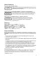
1 Introduction Table 1-1 Port Status LEDs Label Color Link/Activity/ Speed On/Flashing Amber Description Port has a valid link at 10 or 100 Mbps. Flashing indicates activity. On/Flashing Green Port has a valid link at 1000 Mbps. Flashing indicates activity. Off There is no valid link on the port. Port 21/22/23/ Green 24 Off No SFP transceiver plugged in. SFP transceiver plugged in. Port 25/26 On/Flashing Amber Port has a valid link at 10 or 100 Mbps. Flashing indicates activity.
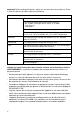
Features and Benefits 1 Power Supply Socket The power socket is on the rear panel. The standard power socket is for the AC power cord. 100-240V~50-60Hz 1.5A AC Power Socket Figure 1-5 Power Supply Socket Features and Benefits Connectivity • 26 10/100/1000 Mbps ports for easy Gigabit Ethernet integration and for protection of your investment in legacy LAN equipment.
1 Introduction Management • “At-a-glance” LEDs for easy troubleshooting • Network management agent: - Manages switch in-band or out-of-band - Supports console, Telnet, SSH, SNMP v1/v2c/v3, RMON (4 groups) and web-based interface 1-6
Chapter 2: Network Planning Introduction to Switching A network switch allows simultaneous transmission of multiple packets via non-crossbar switching. This means that it can partition a network more efficiently than bridges or routers. These switches have, therefore, been recognized as one of the most important building blocks for today’s networking technology.
2 Network Planning Application Examples The SMC8126L2 is not only designed to segment your network, but also to provide a wide range of options in setting up network connections. Some typical applications are described below. Collapsed Backbone The SMC8126L2 is an excellent choice for mixed Ethernet, Fast Ethernet, and Gigabit Ethernet installations where significant growth is expected in the near future.
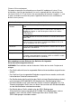
Application Examples 2 Network Aggregation Plan With 26 parallel bridging ports (i.e., 26 distinct collision domains), a switch can collapse a complex network down into a single efficient bridged node, increasing overall bandwidth and throughput. In the figure below, the 10/100/1000BASE-T ports are providing 1000 Mbps connectivity through Layer 2 switches. In addition, the switches are also connecting several servers at 1000 Mbps. 25 26 Server Farm 10/100/1000 Mbps Segments ... ...
2 Network Planning Remote Connections with Fiber Cable Fiber optic technology allows for longer cabling than any other media type. A 1000BASE-SX (MMF) link can connect to a site up to 550 meters away, a 1000BASE-LX (SMF) link up to 5 km, and a 1000BASE-ZX link up to 100 km. This allows a switch to serve as a collapsed backbone, providing direct connectivity for a widespread LAN.
Application Examples 2 Making VLAN Connections This switch support VLANs which can be used to organize any group of network nodes into separate broadcast domains. VLANs confine broadcast traffic to the originating group, and can eliminate broadcast storms in large networks. This provides a more secure and cleaner network environment. VLANs can be based on untagged port groups, or traffic can be explicitly tagged to identify the VLAN group to which it belongs.
2 Network Planning Application Notes 1. Full-duplex operation only applies to point-to-point access (such as when a switch is attached to a workstation, server or another switch). When the switch is connected to a hub, both devices must operate in half-duplex mode. 2. For network applications that require routing between dissimilar network types, you can attach these switches directly to a multi-protocol router. 3.
Chapter 3: Installing the Switch Selecting a Site The SMC8126L2 can be mounted in a standard 19-inch equipment rack or on a flat surface. Be sure to follow the guidelines below when choosing a location. • The site should: - be at the center of all the devices you want to link and near a power outlet.
3 Installing the Switch RJ-45 Connector Figure 3-1 RJ-45 Connections Equipment Checklist After unpacking the switch, check the contents to be sure you have received all the components. Then, before beginning the installation, be sure you have all other necessary installation equipment.
Mounting 3 Mounting This switch can be mounted in a standard 19-inch equipment rack or on a desktop or shelf. Mounting instructions for each type of site follow. Rack Mounting Before rack mounting the switch, pay particular attention to the following factors: • Temperature: Since the temperature within a rack assembly may be higher than the ambient room temperature, check that the rack-environment temperature is within the specified operating temperature range. (See page C-1.
3 2. Installing the Switch Mount the device in the rack, using four rack-mounting screws (not provided). Figure 3-3 Installing the Switch in a Rack 3. If installing a single switch only, turn to “Connecting to a Power Source” at the end of this chapter. 4. If installing multiple switches, mount them in the rack, one below the other, in any order. Desktop or Shelf Mounting 1. Attach the four adhesive feet to the bottom of the first switch. Figure 3-4 Attaching the Adhesive Feet 2.
Installing an Optional SFP Transceiver 3 3. If installing a single switch only, go to “Connecting to a Power Source” at the end of this chapter. 4. If installing multiple switches, attach four adhesive feet to each one. Place each device squarely on top of the one below, in any order. Installing an Optional SFP Transceiver Figure 3-5 Inserting an SFP Transceiver into a Slot The switch supports 1000BASE-SX and 1000BASE-LX, and 1000BASE-ZX SFP-compatible transceivers.
3 Installing the Switch Connecting to a Power Source To connect a device to a power source: 1. Insert the power cable plug directly into the socket located at the back of the device. 100-240V~50-60Hz 1.5A Figure 3-6 Power Socket 2. Plug the other end of the cable into a grounded, 3-pin, AC power source. Note: For international use, you may need to change the AC line cord. You must use a line cord set that has been approved for the receptacle type in your country. 3.
Connecting to the Console Port 3 Wiring Map for Serial Cable Table 3-1 Serial Cable Wiring Switch’s 8-Pin Serial Port Null Modem PC’s 9-Pin DTE Port 6 RXD (receive data) <---------------------------- 3 TXD (transmit data) -----------------------------> 2 RXD (receive data) 3 TXD (transmit data) 5 SGND (signal ground) ------------------------------ 5 SGND (signal ground) No other pins are used.
3 3-8 Installing the Switch
Chapter 4: Making Network Connections Connecting Network Devices The SMC8126L2 is designed to interconnect multiple network segments (or collision domains). It can be connected to network cards in PCs and servers, as well as to hubs, switches or routers. It may also be connected to devices using optional SFP transceivers. Twisted-Pair Devices Each device requires an unshielded twisted-pair (UTP) cable with RJ-45 connectors at both ends.
4 Making Network Connections Connecting to PCs, Servers, Hubs and Switches 1. Attach one end of a twisted-pair cable segment to the device’s RJ-45 connector. Figure 4-1 Making Twisted-Pair Connections 2. If the device is a PC card and the switch is in the wiring closet, attach the other end of the cable segment to a modular wall outlet that is connected to the wiring closet. (See “Network Wiring Connections” on page 4-2.) Otherwise, attach the other end to an available port on the switch.
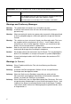
Fiber Optic SFP Devices 4 Equipment Rack (side view) Network Switch w it c h 10 /1 0 0 6724L3 ES4524C Punch-Down Block Patch Panel Wall Figure 4-2 Network Wiring Connections Fiber Optic SFP Devices An optional Gigabit SFP transceiver (1000BASE-SX, 1000BASE-LX or 1000BASE-ZX) can be used for a backbone connection between switches, or for connecting to a high-speed server. Each single-mode fiber port requires 9/125 micron single-mode fiber optic cable with an LC connector at both ends.
4 Making Network Connections 1. Remove and keep the LC port’s rubber cover. When not connected to a fiber cable, the rubber cover should be replaced to protect the optics. 2. Check that the fiber terminators are clean. You can clean the cable plugs by wiping them gently with a clean tissue or cotton ball moistened with a little ethanol. Dirty fiber terminators on fiber cables will impair the quality of the light transmitted through the cable and lead to degraded performance on the port. 3.
Connectivity Rules 4 1000BASE-T Cable Requirements All Category 5 UTP cables that are used for 100BASE-TX connections should also work for 1000BASE-T, providing that all four wire pairs are connected. However, it is recommended that for all critical connections, or any new cable installations, Category 5e (enhanced Category 5) or Category 6 cable should be used. The Category 5e specification includes test parameters that are only recommendations for Category 5.
4 Making Network Connections 10 Mbps Ethernet Collision Domain Table 4-6 Maximum Ethernet Cable Length Type Cable Type Maximum Length Connector 10BASE-T Twisted Pair, Categories 3, 4, 5 or better 100-ohm UTP 100 m (328 ft) RJ-45 Cable Labeling and Connection Records When planning a network installation, it is essential to label the opposing ends of cables and to record where each cable is connected.
Appendix A: Troubleshooting Diagnosing Switch Indicators Table A-1 Troubleshooting Chart Symptom Action Power LED is Off • Check connections between the switch, the power cord, and the wall outlet. • Contact your dealer for assistance. Power LED is Amber • Internal power supply has failed. Contact your local dealer for assistance. Diag LED is Amber • Power cycle the switch to try and clear the condition. • If the condition does not clear, contact your local dealer for assistance.
A Troubleshooting In-Band Access You can access the management agent in the switch from anywhere within the attached network using Telnet, a Web browser, or other network management software tools. However, you must first configure the switch with a valid IP address, subnet mask, and default gateway. If you have trouble establishing a link to the management agent, check to see if you have a valid network connection. Then verify that you entered the correct IP address.
Appendix B: Cables Twisted-Pair Cable and Pin Assignments For 10/100BASE-TX connections, the twisted-pair cable must have two pairs of wires. For 1000BASE-T connections the twisted-pair cable must have four pairs of wires. Each wire pair is identified by two different colors. For example, one wire might be green and the other, green with white stripes. Also, an RJ-45 connector must be attached to both ends of the cable. Caution: DO NOT plug a phone jack connector into any RJ-45 port.
B Cables Table B-1 10/100BASE-TX MDI and MDI-X Port Pinouts Pin 1 MDI Signal Name Transmit Data plus (TD+) MDI-X Signal Name Receive Data plus (RD+) 2 Transmit Data minus (TD-) Receive Data minus (RD-) 3 Receive Data plus (RD+) Transmit Data plus (TD+) 6 Receive Data minus (RD-) Transmit Data minus (TD-) 4,5,7,8 Not used Not used Note: The “+” and “-” signs represent the polarity of the wires that make up each wire pair.
Twisted-Pair Cable and Pin Assignments B You must connect all four wire pairs as shown in the following diagram to support Gigabit Ethernet connections.
B Cables Cable Testing for Existing Category 5 Cable Installed Category 5 cabling must pass tests for Attenuation, Near-End Crosstalk (NEXT), and Far-End Crosstalk (FEXT). This cable testing information is specified in the ANSI/TIA/EIA-TSB-67 standard. Additionally, cables must also pass test parameters for Return Loss and Equal-Level Far-End Crosstalk (ELFEXT).
Appendix C: Specifications Physical Characteristics Ports 22 10/100/1000BASE-T, with auto-negotiation 4 10/100/1000BASE-T shared with 4 SFP transceiver slots Network Interface Ports 1-26: RJ-45 connector, auto MDI/X 10BASE-T: RJ-45 (100-ohm, UTP cable; Category 3 or better) 100BASE-TX: RJ-45 (100-ohm, UTP cable; Category 5 or better) 1000BASE-T: RJ-45 (100-ohm, UTP or STP cable; Category 5, 5e, or 6) *Maximum Cable Length - 100 m (328 ft) Buffer Architecture 0.
C Specifications AC Input 100 to 240 V, 50-60 Hz, 1.5A Power Supply Internal, auto-ranging transformer: 100 to 240 VAC, 50 to 60 Hz Power Consumption 38 Watts Maximum Current 0.25 A @ 115 VAC 0.12 A @ 230 VAC Switch Features Forwarding Mode Store-and-forward Throughput Wire speed Flow Control Full Duplex: IEEE 802.
Compliances C Ethernet, Fast Ethernet, Gigabit Ethernet Full-duplex flow control IEEE 802.1D Spanning Tree Protocol IEEE 802.1w Rapid Spanning Tree Protocol IEEE 802.1s Multiple Spanning Tree Protocol IEEE 802.1Q Virtual LAN ISO/IEC 8802-3 CSMA/CD Compliances CE Mark Emissions FCC Class A Industry Canada Class A EN55022 (CISPR 22) Class A EN 61000-3-2/3 VCCI Class A C-Tick - AS/NZS 3548 (1995) Class A Immunity EN 61000-4-2/3/4/5/6/8/11 Safety UL/cUL (CSA 22.2.
C C-4 Specifications
Appendix D: Ordering Information Table D-1 TIgerSwitch 10/100/1000 Products and Accessories Product Number Description SMC8126L2 26-port Gigabit managed switch SMCBGSLCX1 Single-port 1000BASE-SX Small Form Pluggable (SFP) mini-GBIC transceiver SMCBGLLCX1 Single-port 1000BASE-LX Small Form Pluggable (SFP) mini-GBIC transceiver SMCBGZLCX1 Single-port 1000BASE-ZX Small Form Pluggable (SFP) mini-GBIC transceiver D-1
D D-2 Ordering Information
Glossary 10BASE-T IEEE 802.3 specification for 10 Mbps Ethernet over two pairs of Category 3, 4, or 5 UTP cable. 100BASE-TX IEEE 802.3u specification for 100 Mbps Fast Ethernet over two pairs of Category 5 or better UTP cable. 1000BASE-LX IEEE 802.3z specification for Gigabit Ethernet over two strands of 50/125, 62.5/125 or 9/125 micron core fiber cable. 1000BASE-SX IEEE 802.3z specification for Gigabit Ethernet over two strands of 50/125 or 62.5/125 micron core fiber cable. 1000BASE-T IEEE 802.
Glossary CSMA/CD CSMA/CD (Carrier Sense Multiple Access/Collision Detect) is the communication method employed by Ethernet, Fast Ethernet, or Gigabit Ethernet. End Station A workstation, server, or other device that does not forward traffic. Ethernet A network communication system developed and standardized by DEC, Intel, and Xerox, using baseband transmission, CSMA/CD access, logical bus topology, and coaxial cable. The successor IEEE 802.
Glossary IEEE 802.3z Defines CSMA/CD access method and physical layer specifications for 1000BASE Gigabit Ethernet. (Now incorporated in IEEE 802.3-2005.) LAN Segment Separate LAN or collision domain. LED Light emitting diode used for monitoring a device or network condition. Local Area Network (LAN) A group of interconnected computer and support devices.
Glossary Transmission Control Protocol/Internet Protocol (TCP/IP) Protocol suite that includes TCP as the primary transport protocol, and IP as the network layer protocol. UTP Unshielded twisted-pair cable. Virtual LAN (VLAN) A Virtual LAN is a collection of network nodes that share the same collision domain regardless of their physical location or connection point in the network.
Index Numerics 100 Mbps connectivity rules 4-5 1000 Mbps connectivity rules 4-5 1000BASE-LX fiber cable lengths 4-5 1000BASE-SX fiber cable lengths 4-5 1000BASE-ZX fiber cable lengths 4-5 1000BASE-T pin assignments B-3 ports 1-2, 1-3 100BASE-TX cable lengths 4-5 ports 1-2, 1-3 10BASE-T ports 1-2, 1-3 10BASE-T/100BASE-TX pin assignments B-1 A accessories, ordering D-1 adhesive feet, attaching 3-4 air flow requirements 3-1 applications collapsed backbone 2-2 network aggregation 2-3 remote connections 2-4 VLA
Index M management agent 1-2 features 1-6, C-2, C-3 out-of-band 1-2 SNMP 1-2 web-based 1-2 mounting the switch on a desktop or shelf 3-4 multimode fiber optic cables 4-3 environmental C-1 physical C-1 power C-2 standards, IEEE C-2 status LEDs 1-3 surge suppressor, using 3-1 switch architecture 1-2 switching, introduction to 2-1 T network connections 4-1 examples 2-2 troubleshooting in-band access A-2 power and cooling problems A-1 switch indicators A-1 Telnet A-2 twisted-pair connections 4-1 O V orde
TECHNICAL SUPPORT From U.S.A. and Canada (24 hours a day, 7 days a week) Phn: 800-SMC-4-YOU / 949-679-8000 Fax: 949-502-3400 ENGLISH Technical Support information available at www.smc.com FRENCH Informations Support Technique sur www.smc.com DEUTSCH Technischer Support und weitere Information unter www.smc.com SPANISH En www.smc.com Ud. podrá encontrar la información relativa a servicios de soporte técnico DUTCH Technische ondersteuningsinformatie beschikbaar op www.smc.