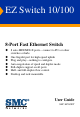
EZ Switch 10/100 8-Port Fast Ethernet Switch 8 auto-MDI/MDI-X ports—connect to PCs or other switches or hubs One Gigabit port for high-speed uplink Plug and play—nothing to configure Auto-negotiation of speed and duplex mode Full-duplex support on all ports Half- and full-duplex flow control Desktop and rack mountable User Guide SMC-EZ109DT
EZ Switch 10/100 User Guide From SMC’s EZ line of low-cost workgroup LAN solutions 6 Hughes Irvine, CA 92618 Phone: (949) 707-2400 May 2001 Pub.
Copyright Information furnished by SMC Networks, Inc. (SMC) is believed to be accurate and reliable. However, no responsibility is assumed by SMC for its use, nor for any infringements of patents or other rights of third parties which may result from its use. No license is granted by implication or otherwise under any patent or patent rights of SMC. SMC reserves the right to change specifications at any time without notice. Copyright © 2001 by SMC Networks, Inc. 6 Hughes, Irvine, CA. All rights reserved.
LIMITED WARRANTY Limited Warranty Limited Warranty Statement: SMC Networks, Inc. (“SMC”) warrants its products to be free from defects in workmanship and materials, under normal use and service, for the applicable warranty term. All SMC products carry a standard 90-day limited warranty from the date of purchase from SMC or its Authorized Reseller.
LIMITED WARRANTY OF ALL OTHER WARRANTIES OR CONDITIONS, EXPRESS OR IMPLIED, EITHER IN FACT OR BY OPERATION OF LAW, STATUTORY OR OTHERWISE, INCLUDING WARRANTIES OR CONDITIONS OF MERCHANTABILITY AND FITNESS FOR A PARTICULAR PURPOSE. SMC NEITHER ASSUMES NOR AUTHORIZES ANY OTHER PERSON TO ASSUME FOR IT ANY OTHER LIABILITY IN CONNECTION WITH THE SALE, INSTALLATION, MAINTENANCE OR USE OF ITS PRODUCTS.
COMPLIANCES FCC Class A This equipment has been tested and found to comply with the limits for a Class A digital device pursuant to Part 15 of FCC Rules. These limits are designed to provide reasonable protection against harmful interference when the equipment is operated in a commercial environment. This equipment generates, uses, and can radiate radio frequency energy, and if not installed and used in accordance with the instruction manual may cause harmful interference to radio communications.
COMPLIANCES Industry Canada - Class A This digital apparatus does not exceed the Class A limits for radio noise emissions from digital apparatus as set out in the interference-causing equipment standard entitled “Digital Apparatus”, ICES-003 of Industry Canada. Cet appareil numérique respecte les limites de bruits radioélectriques applicables aux appareils numériques de Classe A prescrites dans la norme sur le matérial brouilleur: “Appareils Numériques”, NMB-003 édictée par l’Industrie.
COMPLIANCES Wichtige Sicherheitshinweise (Germany) 1. Bitte lesen Sie diese Hinweise sorgfältig durch. 2. Heben Sie diese Anleitung für den späteren Gebrauch auf. 3. Vor jedem Reinigen ist das Gerät vom Stromnetz zu trennen. Verwenden Sie keine Flüssigoder Aerosolreiniger. Am besten eignet sich ein angefeuchtetes Tuch zur Reinigung. 4. Die Netzanschlu ßsteckdose soll nahe dem Gerät angebracht und leicht zugänglich sein. 5. Das Gerät ist vor Feuchtigkeit zu schützen. 6.
COMPLIANCES iv
TABLE OF CONTENTS About the EZ Switch 10/100 . . . . . . . . . . . . . . . . . .1 Features and Benefits . . . . . . . . . . . . . . . . . . . . . . . . . . . . . . . . 2 Front Panel LEDs . . . . . . . . . . . . . . . . . . . . . . . . . . . . . . . . . . . 3 Rear Panel . . . . . . . . . . . . . . . . . . . . . . . . . . . . . . . . . . . . . . . . 4 Installing the Switch . . . . . . . . . . . . . . . . . . . . . . . .5 Equipment Checklist . . . . . . . . . . . . . . . . Selecting a Site . . . . . . . .
TABLE OF CONTENTS vi
ABOUT THE EZ SWITCH 10/100 ABOUT THE EZ SWITCH 10/100 The EZ Switch 10/100 SMC-EZ109DT is an 8-port Fast Ethernet switch with one Gigabit uplink port. The 10BASE-T/100BASE-TX ports deliver dedicated 10/100 Mbps links to each attached LAN segment. The Gigabit port operates at 100 and 1000 Mbps. Each port on the switch supports automatic MDI/MDI-X detection. This means that you can use either straight-through or crossover cables to connect to any other network device.
ABOUT THE EZ SWITCH 10/100 Features and Benefits ◆ Auto configuration for MDI/MDI-X cable connection allows connections to servers, workstations, hubs or switches to be made with straight-through cabling ◆ One Gigabit uplink port for high-speed uplink ◆ Auto-negotiation of half or full duplex on all ports ◆ IEEE 802.3 and 802.
ABOUT THE EZ SWITCH 10/100 Front Panel LEDs The front panel of the switch provides status LEDs for “at-a-glance” system monitoring. The following table details the functions of the various indicators: Port and System Status LEDs LED Condition Status Power On The switch is receiving power. Off The port has not established any network connection. On The port has established a valid network connection.
ABOUT THE EZ SWITCH 10/100 Port and System Status LEDs LED Condition Status Gigabit Port LINK/ ACT Off The port has not established any network connection. On The port has established a valid network connection. Flashing The port has established a valid network connection and traffic is passing through the port. 10/100M On The port has established a valid network connection and communications have been set to 100 Mbps.
INSTALLING THE SWITCH INSTALLING THE SWITCH Equipment Checklist After unpacking the EZ Switch 10/100, check the contents of the box to be sure you have received the following components: • EZ Switch 10/100 SMC-EZ109DT • Appropriate AC power cable • Four adhesive foot pads & rackmount kit • SMC Warranty Registration Card • This User Guide Selecting a Site Be sure to follow the site selection guidelines below when choosing a location: Select a suitable location for the switch: • It should
INSTALLING THE SWITCH Make sure that a properly grounded power outlet is within 2.44 meters (8 feet) of the switch and is powered from an independent circuit breaker. As with any equipment, using a filter or surge suppressor is recommended. Instructions Positioning the Switch The EZ Switch 10/100 can be placed anywhere there is enough flat space, such as on a desktop or a shelf. 1. Attach the four adhesive feet to the bottom of the switch. 2.
INSTALLING THE SWITCH Note: It is not necessary to power off the switch before connecting or disconnecting any UTP cables, as these actions will not disrupt the operation of other devices attached to the switch. RJ-45 10/100 Mbps Connections For twisted-pair devices, connect each PC to an RJ-45 port on the switch with a twisted-pair cable segment, maximum 100 meters (328 feet). Use Category 3, 4, or 5 cable for 10 Mbps connections, and Category 5 cable for all 100 Mbps connections.
INSTALLING THE SWITCH Sample Applications This switch segments your network, significantly increasing both bandwidth and throughput. Any port on the switch can be attached to a hub (a shared collision domain) or provide a dedicated link to a single network device (such as a workstation or server). When a port on the switch is connected to a hub (a 10 or 100 Mbps repeater), the bandwidth provided by that port is shared by all the devices connected to the attached hub.
INSTALLING THE SWITCH Gigabit Uplink Port - You can use the Gigabit port to support applications such as high-speed file servers, or for connecting to a collapsed backbone switch. In the figure below, the EZ Switch 10/100 is operating as a collapsed backbone for a small LAN. It is providing dedicated 20 Mbps full-duplex connections to workstations and 200 Mbps full-duplex connections to power users and servers. The Gigabit port is used to provide a 2 Gbps full-duplex link to a server.
TROUBLESHOOTING TROUBLESHOOTING 1. Symptom Power LED does not light after power on. Probable Causes Power outlet or power cord may be defective. Possible Solutions • Check for loose connections. • Check the power outlet by using it for another device. • Replace the power cord. 2. Symptom Link LED does not light after connection is made. Probable Causes Switch port, network card or cable may be defective. Possible Solutions • Check that the switch and attached device are both powered on.
CABLES CABLES CABLE SPECIFICATIONs Maximum 10BASE-T, 100BASE-TX and 1000BASE-T Cable Length Cable Type Max. Length Connector 10BASE-T Cat. 3, 4, 5 100-ohm UTP 100 m (328 ft) RJ-45 100BASE-TX Cat. 5 100-ohm UTP 100 m (328 ft) RJ-45 1000BASE-T Cat.
CABLES RJ-45 Connector Pin Assignments Caution: DO NOT plug a phone jack connector into any RJ-45 port. Use only twisted-pair cables with RJ-45 connectors that conform with FCC standards. 10BASE-T/100BASE-TX Pin Assignments An Ethernet or Fast Ethernet twisted-pair link segment requires two pairs of wires. Each wire pair is identified by two different colors. Each wire pair must be attached to the RJ-45 connector in a specific orientation detailed below.
CABLES 1000BASE-T Pin Assignments The table below shows the 1000BASE-T MDI and MDI-X port pinouts. These ports require that all four pairs of wires be connected. Note that for 1000BASE-T operation, all four pairs of wires are used for both transmit and receive. Use 100-ohm Category 5 or 5e unshielded twisted-pair (UTP) or shielded twisted-pair (STP) cable for 1000BASE-T connections. Also be sure that the length of any twisted-pair connection does not exceed 100 meters (328 feet).
CABLES 1000BASE-T Cable Requirements All Category 5 UTP cables that are used for 100BASE-TX connections should also work for 1000BASE-T, providing that all four wire pairs are connected. However, it is recommended that for all critical connections, or any new cable installations, Category 5e (enhanced Category 5) cable should be used. The Category 5e specification includes test parameters that are only recommendations for Category 5.
CABLES Adjusting Existing Category 5 Cabling to Run 1000BASE-T If your existing Category 5 installation does not meet one of the test parameters for 1000BASE-T, there are basically three measures that can be applied to try and correct the problem: 1. Replace any Category 5 patch cables with high-performance Category 5e cables. 2. Reduce the number of connectors used in the link. 3. Reconnect some of the connectors in the link.
SPECIFICATIONS SPECIFICATIONS Access Method CSMA/CD Ports 8 10BASE-T/100BASE-TX, with auto-negotiation 1 100BASE-TX/1000BASE-T with auto-negotiation Network Interface RJ-45: 100 ohm, UTP cable 10BASE-T - Categories 3, 4, or 5 100BASE-TX - Category 5 1000BASE-T - Category 5 or 5e LEDs System: Power Ports 1-8: Link/Act, FDX/COL, 10/100M Gigabit Port: Link/Act, FDX/COL, 100M, 1000M Switching Method Store-and-forward MAC Address Table 4K total Memory Buffer 2 MBytes per system Filtering/Forwarding/Learning Rat
SPECIFICATIONS Weight 0.85 kg (1.87 lbs) Temperature Operating: 0 to 40 °C (32 to 104 °F) Storage: -40 to 85 °C (-40 to 185 °F) Humidity 5% to 95% non-condensing Power Requirements 100 to 240 VAC (±10%) 50 to 60 Hz (±3 Hz) Power Consumption 15 Watts maximum @100 - 240 VAC Heat Dissipation 51 BTU/hr maximum @100 - 240 VAC Maximum Current 0.4 A @ 115 VAC 0.2 A @ 240 VAC Standards IEEE 802.3 IEEE 802.3u IEEE 802.
SPECIFICATIONS 18
FOR TECHNICAL SUPPORT, CALL: From U.S.A. and Canada (24 hours, 7 days a week) (800) SMC-4-YOU; (949) 707-2400; (949) 707-2460 (Fax) From Europe (8:00 AM - 5:30 PM UK Greenwich Mean Time) 44 (0) 1188 748740; 44 (0) 1189 748741 (Fax) INTERNET E-mail address: techsupport@smc.com european.techsupport@smc-europe.com Driver updates: http://www.smc.com/support.html World Wide Web: http://www.smc.com/ FTP Site: ftp.smc.com FOR LITERATURE OR ADVERTISING RESPONSE, CALL: U.S.A.