NEXT - Warranty Statement
BACK - Intro NEXT - Equipment Checklist Limited Warranty Limited Warranty Statement: SMC Networks, Inc. ("SMC") warrants its products to be free from defects in workmanship and materials, under normal use and service, for the applicable warranty term. All SMC products carry a standard 90-day limited warranty from the date of purchase from SMC or its Authorized Reseller.
WARRANTIES OR CONDITIONS, EXPRESS OR IMPLIED, EITHER IN FACT OR BY OPERATION OF LAW, STATUTORY OR OTHERWISE, INCLUDING WARRANTIES OR CONDITIONS OF MERCHANTABILITY AND FITNESS FOR A PARTICULAR PURPOSE. SMC NEITHER ASSUMES NOR AUTHORIZES ANY OTHER PERSON TO ASSUME FOR IT ANY OTHER LIABILITY IN CONNECTION WITH THE SALE, INSTALLATION, MAINTENANCE OR USE OF ITS PRODUCTS.
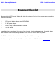
BACK - Warranty Statement NEXT - Install Instructions Equipment Checklist After unpacking the EZ Connect Wireless AP, check the contents of the box to be sure you have received the following components: • • • • 1 EZ Connect Wireless Access Point (SMC2655W) 1 5 VDC power adapter 1 Driver, Utility, and Documentation CD-ROM This User Guide Immediately inform your dealer in the event of any incorrect, missing or damaged parts.
BACK - Equipment Checklist NEXT - Utility Installation SMC2655W: Installation Instructions 1) Site Location – Choose a location for your SMC2655W Wireless Access Point. Usually, the best location is at the center of your wireless coverage area, if possible within line-of-sight of all wireless devices. 2) Placement - Put the Access Point in a position that gives it maximum coverage. Normally, the higher you place the antenna, the better the performance.
BACK - Install Instructions NEXT - Application-based AP Configuration Utility Installation Windows 98/NT/Me/2000/XP This section will describe the process for installing the utility program for your SMC2655W Access Point. Step 1: Insert the Utility and Documentation CD. Step 2: Double-click the "My Computer" icon your desktop and browse to your CD-ROM drive. (Note: In most cases, the letter of your CD-ROM drive is D.) Step 3: Open the Utility folder and run the [Setup.exe] file.
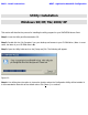
Figure 1.1 Step 5: You will be given the option to choose the folder name for the Utility program. It is recommended to leave this at the default value. Click [Next >] to continue.
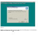
Figure 1.2 Step 6: The wizard will finalize the installation. Figure 1.
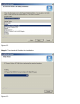
Step 7: Once the files are installed, you will be given the option of adding a shortcut to the utility in your startup folder. If you click [Yes], Windows will automatically run the utility upon boot up. If you click [No], you will need to browse through the Start Menu in order to run the application. Figure 1.4 Figure 1.
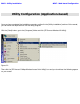
BACK - Utility Installation NEXT - Web-based Configuration Utility Configuration (Application-based) Once you have completed the installation procedure outlined in the [Utility Installation] section of this manual, you can follow the steps below to run the utility program. Click the [Start] button, go to the [Programs] folder and click [EZ Connect Wireless AP Utility]. Figure 1.
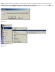
Figure 1.1 The utility will automatically scan for your AP. If you do not see the "MiniAP" in the drop down menu, please select the [Browse Again] option from the drop down menu. Then enter the word "default" (all lowercase) for the password. This is the factory default password for the Access Point. Then press [Login] to continue.
Figure 1.2 The screen in Figure 1.2 shows you the information that is currently set on the AP. The default SSID is "WLAN", the default IP address is 192.168.2.50 and the default gateway is 192.168.2.1. This is very important information to note when configuring your wireless network so that it is integrated properly with your existing network. For instance, if your existing LAN is operating on a 10.0.0.1 IP scheme, then you should change the IP address of the Access Point to 10.0.0.
Figure 1.3 Now you can manually specify the IP of your Access Point, the subnet mask, and its gateway. You can also change the SSID to the desired workgroup name and you can change the channel to a specific frequency to avoid wireless interference from other nearby devices.
Figure 1.4 After clicking [Setup], you can enable MAC address control or manage the Wired Equivalent Privacy (WEP) security key. You simply need to select the [WEP 64bit] or [WEP 128bit] options in order to activate the desired encryption. You must manually enter the key. The SMC2655W Access Point supports Wired Equivalent Privacy (WEP) in order to secure your wireless network and prevent unauthorized access. For more secure data transmissions, set encryption to "128-bit" or "64-bit".
Figure 1.5 Figure 1.
For HEX (0-9, A-F) "Key Format", the security is enabled by entering 10-digit keys for the 64-bit WEP configuration, and 26-digit keys for a 128-bit WEP configuration. For ASCII "Key Format", the security is enabled by entering 5-letter keys for 64-bit WEP, and 13-letter keys for 128-bit WEP. Note that there are 4 different keys to choose from. Choose the Key that has the encryption string you prefer. The wireless clients must be configured in this same fashion. Figure 1.
Figure 1.8 The table below shows all the default values for this AP: Setting AP Name SSID Channel IP Address Subnet Mask Gateway Encryption MAC Access Control Password Default Value MiniAP WLAN 1 192.168.2.50 255.255.255.0 192.168.2.
BACK - Application-based Configuration NEXT - Firmware Update Procedure Utility Configuration (Web-based) The default IP address of the SMC2655W is 192.168.2.50. If you prefer to configure the AP via a web browser rather than the utility program, you can do so by opening your web browser and going to "http://192.168.2.50". You need to be sure that your computer is configured in the same subnet in order to access the Access Point's web management interface. For example, your machine's IP should be 192.
Figure 1.1 Click the [Configuration] link on the left and a drop down menu will appear on the page. Then click the [General] option to continue. The "Access Point Name" is simply used to identify the AP. This is not the Service Set Identifier. The "ESSID" field represents the wireless workgroup name. Your wireless clients must have the same value configured in their network settings. You can also choose the operating radio channel.
Figure 1.2 Click the [WEP] link on the left in order to access the 64/128-bit encryption configuration. For HEX (0-9, A-F) "Key Format", the security is enabled by entering 10-digit keys for the 64-bit WEP configuration, and 26-digit keys for a 128-bit WEP configuration. Be sure to type "0x" before entering the HEX key. For ASCII "Key Format", the security is enabled by entering 5-letter keys for 64-bit WEP, and 13-letter keys for 128-bit WEP. Note that there are 4 different keys to choose from.
Figure 1.3 Click the [Access Control] link on the left in order to access and configure the MAC Address List. In the field on the right, enter the new MAC address of a client that will be allowed to access the network. The format is 12 hexadecimal digits with colons separating each pair of digits (e.g. - 00:50:BA:CA:6B:BC). Then click the [Add] button. The page will be refreshed and the MAC address you entered will appear in the "Address List".
Figure 1.4 Click the [TCP/IP] link on the left and then click [General] to view the current IP configuration of the Access Point. You can manually enter new IP info as well in order to easily integrate the unit into your existing LAN. Then press the [Apply] button to save your changes.
Figure 1.
BACK - Web-based Configuration NEXT - Frequently Asked Questions Firmware Update Procedure Once you have completed the installation procedure outlined in the [Utility Installation] section of this manual, you can follow the steps below to run the firmware upgrade utility program. Click the [Start] button, go to the [Programs] folder and click [EZ Connect Wireless AP Utility]. Figure 1.
Figure 1.1 Enter the administrator password in order to log into the Access Point. Then you will see the details of the current firmware. Click the [Open File] button, browse to the folder containing the latest firmware revision, and open it. Then compare the details under the "current version" and "new version" sections to be sure that you are in fact upgrading the firmware to a more recent revision.
Figure 1.2 Restore to Factory Defaults Procedure 1) Locate the [Default] button on the back of the SMC2655W Access Point. 2) Unplug the power from the back of the AP for 10 seconds. 3) Depress the [Default] button for 3 seconds. 4) Plug the power connector into the AP while depressing the [Default] button. 5) Release the [Default] button after 3 seconds. Wait 3 seconds and then depress the [Default] button again. 6) The "LNK/ACT" and "TX/RX" LEDs will blink once per second about 10-12 times.
BACK - Firmware Update Procedure NEXT - Glossary Troubleshooting / FAQs If mobile users do not have roaming access to the SMC2655W access point: Make sure that all the SMC2655Ws and stations in the ESS in which the WLAN mobile users can roam are configured to the same WEP setting, SSID, and authentication algorithm.
2.4GHz band, and the 802.11a standard defines 54 Mbps in the 5GHz band. What is Infrastructure? In order for your wireless components to interact with traditional wired networks they need a media bridge to translate for them. This is where INFRASTRUCTURE or Network mode comes into play. An ACCESS POINT is attached to the network using CAT-5 Ethernet cable attaching to a hub, switch or another PC. Wireless PC’s can then communicate to Wired Ethernet computers through this access point.
WEP is designed to provide the same level of security as that of a wired LAN. LANs are inherently more secure than WLANs because LANs are somewhat protected by the physicalities of their structure, having some or all part of the network inside a building that can be protected from unauthorized access. WLANs, which are over radio waves, do not have the same physical structure and therefore are more vulnerable to tampering.
Operating Channel: 11 Channels (US, Canada) 13 Channels (Europe) 14 Channels (Japan) RF Output Power: 20 dBm Sensitivity: -82 dBm @ 11 Mbps Operating Systems: Windows 98/Me/NT/2000/XP Network Management: Web-based Interface Utility (Access Point Manager) - Windows-based Antenna Type: External Dipole Antenna LED Indicators: Power/Status GREEN: Power On Wireless Tx/Rx Green LED blinking: Tx/Rx activity Ethernet Tx/Rx Green LED blinking: Tx/Rx activity Power Voltage: 5 Volt DC Dimensions: 117 x 62 x 22 mm Envi
are many variables such as barrier composition and construction, as well as local environmental interference that may impact your actual distances and cause you to experience distance thresholds far lower than those posted below. If you have any questions or comments regarding the features or performance of this product, or if you would like information regarding our full line of wireless products, visit us on the web at www.smc.com, or call us toll-free at 800.SMC.4YOU.
BACK – Frequently Asked Questions NEXT - Featured Products Glossary 10BaseT - Physical Layer Specification for Twisted-Pair Ethernet using Unshielded Twisted Pair wire at 10Mbps. This is the most popular type of LAN cable used today because it is very cheap and easy to install. It uses RJ45 connectors and has a cable length span of up to 100 meters. There are two versions, STP (Shielded Twisted Pair) which is more expensive and UTP (Unshielded Twisted Pair), the most popular cable.
DSL - DSL stands for Digital Subscriber Line. A DSL modem uses your existing phone lines to transmit data at high speeds. Ethernet - A standard for computer networks. Ethernet networks are connected by special cables and hubs, and move data around at up to 10 million bits per second (Mbps). ESS - ESS (ESS-ID, SSID) stands for "Extended Service Set". More than one BSS is configured to become an Extended Service Set. LAN mobile users can roam between different BSSs in an ESS (ESS-ID, SSID).
switch used to connect to other hubs or switches without requiring a crossover cable. The MDI port does not cross the transmit and receive lines, which is done by the regular ports (MDI-X ports) that connect to end stations. The MDI port connects to the MDI-X port on the other device. There are typically one or two ports on a device that can be toggled between MDI (not crossed) and MDI-X (crossed).
BACK – Glossary NEXT - Technical Support Featured Products Thank you for purchasing SMC products! Users who have purchased the SMC2655W have also purchased the following devices: The Barricade™ Plus Cable/DSL Broadband Router (7004FW) is the ideal networking solution for both the home and business user. Easily connect this router to the Internet in minutes using SMC’s new 3-Click Install Wizard.
To complement the incorporated SPI firewall functions, the Barricade Plus Router has a built-in VPN tunnel that supports IPSec and PPTP Client/Server connectivity. This VPN functionality is the perfect solution for remotely accessing a network securely by establishing an authenticated and encrypted tunnel over the Internet. No matter what connection you set up, you can be well assured that your data is being transmitted and exchanged in the most secure manner.
SMC’s EZ Switch™ 10/100s are dual-speed desktop network switches that are as easy to install and use as an ordinary hub, with the added dimension of dramatically improving network performance by offering speeds up to 200 Mbps per port. Moreover, the 5 port, SMC-EZ6505TX features Auto MDI/MDI-X on each port, providing added functionality and ease of use.
The Barricade™ Wireless Cable/DSL Broadband Router (SMC7004VWBR) is the ideal networking solution for any home and business user. This platform independent multi-functional router combines a 4-port 10/100 Mbps dual-speed switch, an 802.11b wireless access point, Stateful Packet Inspection (SPI) firewall security, network management, and Virtual Private Network (VPN) pass-through support into one convenient device.
BACK – Featured Products Technical Support FOR TECHNICAL SUPPORT, CALL: From U.S.A. and Canada (24/7) (800) SMC-4-YOU; (949) 707-2400; (949) 707-2460 (Fax) From Europe (8:00 AM - 5:30 PM UK Greenwich Mean Time) 44 (0) 1189 748740; 44 (0) 1189 748741 (Fax) INTERNET E-mail addresses: techsupport@smc.com Driver updates: http://www.smc.com/index.cfm?action=tech_support_drivers_downloads FOR LITERATURE OR ADVERTISING RESPONSE, CALL: U.S.A.