EZ ConnectTM N Draft 11n Wireless USB2.
Wireless USB Adapter User Guide The easy way to make all your network connections 20 Mason Irvine, CA 92618 Phone: (949) 679-8000 October 2007 Pub.
Information furnished by SMC Networks, Inc. (SMC) is believed to be accurate and reliable. However, no responsibility is assumed by SMC for its use, nor for any infringements of patents or other rights of third parties which may result from its use. No license is granted by implication or otherwise under any patent or patent rights of SMC. SMC reserves the right to change specifications at any time without notice. Copyright © 2007 by SMC Networks, Inc. 20 Mason Irvine, CA 92618 All rights reserved.
Limited Warranty Limited Warranty Statement: SMC Networks, Inc. (“SMC”) warrants its products to be free from defects in workmanship and materials, under normal use and service, for the applicable warranty term. All SMC products carry a standard 90-day limited warranty from the date of purchase from SMC or its Authorized Reseller. SMC may, at its own discretion, repair or replace any product not operating as warranted with a similar or functionally equivalent product, during the applicable warranty term.
NOT BE LIABLE UNDER THIS WARRANTY IF ITS TESTING AND EXAMINATION DISCLOSE THE ALLEGED DEFECT IN THE PRODUCT DOES NOT EXIST OR WAS CAUSED BY CUSTOMER’S OR ANY THIRD PERSON’S MISUSE, NEGLECT, IMPROPER INSTALLATION OR TESTING, UNAUTHORIZED ATTEMPTS TO REPAIR, OR ANY OTHER CAUSE BEYOND THE RANGE OF THE INTENDED USE, OR BY ACCIDENT, FIRE, LIGHTNING, OR OTHER HAZARD.
Compliances Federal Communication Commission Interference Statement This equipment has been tested and found to comply with the limits for a Class B digital device, pursuant to Part 15 of the FCC Rules. These limits are designed to provide reasonable protection against harmful interference in a residential installation.
Australia/New Zealand AS/NZS 4771 Japan VCCI Class B Taiwan DGT (NCC) 根據交通部低功率管理辦法規定: 第十二條 經型式認證合格之低功率射頻電機,非經許可,公司、商號或使用者均不得擅 自變更頻率、加大功率或變更原設計之特性及功能。 第十四條 低功率射頻電機之使用不得影響飛航安全及干擾合法通信;經發現有干擾現象 時,應立即停用,並改善至無干擾時方得繼續使用。前項合法通信,指依電信 法規定作業之無線電通信。低功率射頻電機須忍受合法通信或工業、科學及醫 療用電波輻射性電機設備之干擾。 EC Conformance Declaration Marking by the above symbol indicates compliance with the Essential Requirements of the R&TTE Directive of the European Union (1999/5/EC).
Council recommendation 1999/519/EC of 12 July 1999, limitations of exposure of the general public to electromagnetic fields (0 Hz to 300 GHz) Czech SMC Networks tímto prohlašuje, že tento Radio LAN device je ve shodě se základními požadavky a dalšími příslušnými ustanoveními směrnice 1999/5/ES. Danish Undertegnede SMC Networks erklærer herved, at følgende udstyr Radio LAN device overholder de væsentlige krav og øvrige relevante krav i direktiv 1999/5/EF.
Icelandic Hér með lýsir SMC Networks yfir því að Radio LAN device er í samræmi við grunnkröfur og aðrar kröfur, sem gerðar eru í tilskipun 1999/5/EC. Norwegian SMC Networks erklærer herved at utstyret Radio LAN device er i samsvar med de grunnleggende krav og øvrige relevante krav i direktiv 1999/5/EF.
Countries of Operation & Conditions of Use in EC / EFTA member states English This device is a 2.4 GHz wireless LAN transceiver, intended for indoor home and office use in all notified EC and EFTA member states. In accordance with article 6.4 of the R&TTE Directive 1999/5/EC the following EC/ EFTA member states have been notified: Austria, Belgium, Denmark, Finland, France, Germany, Italy, Luxembourg, Netherlands, Norway, Spain, Sweden, Switzerland, United Kingdom, Portugal, Greece, Ireland, Iceland.
vi
About This Guide Purpose This guide details the hardware features of the wireless USB adapter, including its physical and performance-related characteristics, and how to install the device and use its configuration software. Audience This guide is for PC users with a working knowledge of computers. You should be familiar with Windows operating system concepts.
vi
Contents Chapter 1: Introduction 1-1 Features System Requirements Package Checklist Hardware Description LED Indicators WPS Button 1-1 1-2 1-2 1-2 1-3 1-3 Chapter 2: Driver and Utility Installation 2-1 Chapter 3: Configuration 3-1 Accessing the EZ Connect Wireless Utility Wireless Utility Configuration Profile Network Advanced Statistics WMM WPS Radio Setting About Help Chapter 4: Network Planning Network Topologies Ad Hoc Wireless LAN Infrastructure Wireless LAN Chapter 5: AP Mode Configuration Swi
Contents About Help Appendix A: Troubleshooting USB Adapter Installation Problems Network Connection Problems Uninstalling the Utility Appendix B: Specifications viii 5-10 5-11 A-1 A-1 A-1 A-2 B-1
Chapter 1: Introduction The SMCWUSBS-N is a Wi-Fi (IEEE 802.11b/g/n) Wireless USB Adapter that enables wireless connectivity for your PC. The device provides a Wi-Fi client solution for PCs using a USB 2.0 interface. The USB adapter also includes a comprehensive configuration, site survey, and profile management utility that can be installed on a Windows 2000, Windows XP or Windows Vista system. WPS Button WPS Indicator Link/Activity Indicator Features • Wi-Fi compliant with IEEE 802.11n (draft 2.
Introduction System Requirements Before you install the EZ Connect Wireless USB Adapter, check your system meets the following requirements: • 2.4 GHz 802.11n (draft 2.0) or 802.11b/g wireless network. • Microsoft Windows 2000, XP or Vista. • A Notebook or desktop computer with: - 300MHz CPU or above. Available USB2.0 port 20MB of available hard disk space CD-ROM drive Package Checklist The Wireless USB Adapter package includes these items: • EZ Connect N Wireless USB 2.
LED Indicators LED Indicators The Wireless USB Adapter includes two status LED indicators, as described in the following figure and table. WPS Authentication 802.11b/g/n Link/Activity LED Status Description WPS On/Flashing Green Indicates the WPS button is pressed, and WPS authentication is in progress. Off Indicates WPS authentication is not in progress. On/Flashing Green Indicates the power is on, and the 802.11b/g/n radio is enabled. Flashing indicates wireless network activity.
Introduction 1-4
Chapter 2: Driver and Utility Installation The CD-ROM that comes with the package contains the USB driver and software utility for the Wireless USB Adapter. New or updated drivers can be downloaded from SMC’s web site at http://www.smc.com. The installation screens are similar for all Microsoft Windows systems. The installation interface for only Windows XP is shown in this user guide.
Driver and Utility Installation 3. Click Next to continue the installation. Figure 2-2. EZ Connect N CD - Driver and Utility Installation 4. Wait for the software installation procedure to complete. Figure 2-3.
5. When the “Installation Complete” message displays, click Finish. Figure 2-4. EZ Connect N CD - Installation Finished 6. Insert the Wireless USB Apapter in an available USB slot. The new hardware is detected and automatically installed. Now the device is ready to use. Figure 2-5.
Driver and Utility Installation 2-4
Chapter 3: Configuration Accessing the EZ Connect Wireless Utility Once the the SMC EZ Connect Wireless utility installation is complete, the configuration utility can be accessed by selecting the “SMC EZ Connect N Wireless Utility” icon from the “SMC EZ Connect N Wireless Utility” folder. Figure 3-1. Accessing EZ Connect N Wireless Utility A quick launch icon will appear in the lower right-hand corner of the task bar. When the icon is blue, it indicates that the wireless connection is in progress.
Configuration Wireless Utility Configuration The SMC EZ Connect Wireless utility screen includes the options in the table below. For details on the configuration for each feature, see the corresponding page number. Table 3-1.
Wireless Utility Configuration Profile The profile settings page allows you to set and save different wireless settings. You can activate the suitable profile according to the environment where the wireless connection is used. Figure 3-3. Profile - System Configuration To Add a profile, click the Add button and configure the following displayed items: System Configure — Configure the wireless network. • Profile Name – The name of the profile.
Configuration - Infrastructure – An integrated wireless and wired LAN is called an Infrastructure configuration. Select Infrastructure to associate to an AP. • Power Save Mode (available when “Infrastucture” is selected as the network type) – Enable or disable the power save operation. (Default: CAM) - CAM – Constantly awake mode, which always keeps the radio on. - PSM – Power save mode, which turns the radio off when no data is being transferred.
Wireless Utility Configuration • Authentication / Encryption — Configure authentication and encryption to match the security of the wireless network. Figure 3-4. Profile - Authentication\Encryption The displayed items on this page can be described as follows: • Authentication – Select the authentication mode. For an infruastructure network, seven modes are supported by the Wireless USB Adapter, including Open, Shared, LEAP, WPA and WPA-PSK, WPA2 and WPA2-PSK.
Configuration Figure 3-5. Authentication - LEAP - WPA / WPA-PSK – Wi-Fi Protected Access (WPA) employs a combination of technologies to provide an enhanced security solution for wireless networks. The WPA Pre-shared Key (WPA-PSK) mode for small networks uses a common password phrase that must be manually distributed to all clients that want to connect to the netwok. - WPA2 / WPA2-PSK – WPA2 is a futher security enhancement that includes the now ratified IEEE 802.11i wireless security standard.
Wireless Utility Configuration network access control that uses a RADIUS server on the local network for user authentication. The 802.1X standard uses the Extensible Authentication Protocol (EAP) to pass user credentials (either digital certificates, usernames and passwords, or other) from the client to the RADIUS server. Figure 3-6. Profile - 802.1X • EAP Method – Select an 802.1X authentication method. - PEAP – Protected Extensible Authentication Protocol.
Configuration • Tunnel Authentication – Selects the tunnel authentication protocol. This pull-down menu is only available when the authentication type is PEAP or TTLS. When EAP-FAST is used, the protocol setting is always Generic Token Card and cannot be changed. - EAP-MSCHAP v2 – This authentication uses a dynamic session-based WEP key derived from the client adapter and RADIUS server to encrypt data.
Wireless Utility Configuration Network The network setting page allows you to set and save different wireless settings. You can activate the suitable profile according to the environment where the wireless connection is used. Figure 3-7. Network The displayed items on this page can be described as follows: Sort by — Indicate that the AP list is sorted by SSID, Channel or Signal. Show dBm — Show the dBm strength of the received signal.
Configuration Table 3-2. Icon Indications Icons Description The network supports 802.11g connections The network supports 802.11n connections You can press the button on the buttom right corner to display the network status, as shown below. Note: The maximum transmit link speed of this wireless USB adpater is 150 Mbps and the maximum receive link speed is 300 Mbps. Figure 3-8. Network Status You can also double-click one of the access points on the list to display its general, WPS, CCX and 802.
Wireless Utility Configuration Advanced The Advanced page allows you to configure extended features for the wireless network. Figure 3-10. Advanced The displayed items on this page can be described as follows: Wireless Mode — Select 802.11 B/G/N mix or 802.11 B/G mix as the wireless mode. Enable TX Burst — Enable the option to accelerate the data transmit rate. Enable TCP Window Size — Adjust TCP window size automatically for better performance.
Configuration Country Region Code — Select the country in which the device is being used. Setting the country code restricts operation of the device to radio channels and transmit power levels permitted for wireless networks as specified by the local regulatory authority Statistics The statistics page displays the connected-related statistics with detail counter information. Click Reset Counter to reset all the items back to 0 Figure 3-11.
Wireless Utility Configuration WMM Wi-Fi Multimedia (WMM), also known as Wireless Multimedia Extensions (WME), is a Wi-Fi Alliance interoperability certification. It provides basic Quality of Service (QoS) features for IEEE 802.11 wireless networks. Figure 3-12. WMM The displayed items on this page can be described as follows: WMM Enable — Enable WMM function. • WMM - Power Save Enable – Enable the power save mode.
Configuration WPS Wi-Fi Protected Setup (WPS) is based on push-button or PIN (Personal Identification Number) entry authentication to provide strong WPA/WPA2 encryption keys to client devices. Users can push a button on the access point and the client device to exchange the encryption key. With a PIN, users can enter a code generated by the client device to connect to the network. WPS Setup - PBC (Push-button Configuration) 1.
Wireless Utility Configuration - Registrar – A registrar is the network enrollment center. If the Wireless USB Adapter is set as a registrar, click the Rescan button on the utility WPS setup page to search for WPS-enabled wireless devices near you. All enrollees found will be displayed in the WPS Profile List. Select an enrollee on the list and click the Connect button to activate the connection. 3.
Configuration Radio Setting Press the Radio On/Off icon to disable or enable the radio signal connection. About The about page displays the information about version numbers of the configuration utility, firmware and other information of the device. Click the WWW.SMC.COM button to visit the SMC website for other information. Figure 3-14.
Wireless Utility Configuration Help The help page provides detailed information about each setting of the EZ Connect utility. Click the contents on the left screen and view the information on the right screen. Figure 3-1.
Configuration 3-18
Chapter 4: Network Planning SMC's EZ Connect Wireless Solution supports a stand-alone wireless network configuration, as well as an integrated configuration with Ethernet LANs.
Network Planning The infrastructure configuration not only extends the accessibility of wireless PCs to the wired LAN, but also increases the effective wireless transmission range for wireless PCs by passing their signal through one or more access points. A wireless infrastructure can be used for access to a central database, or for connection between mobile workers, as shown in the following figure.
Chapter 5: AP Mode Configuration The USB Adapter's utility can extend the functionality of the device by adding an Access Point (AP) mode to its normal client capabilities. In AP mode, the USB Adapter operates as a "Soft AP." The Soft AP feature creates a Wireless LAN to Ethernet bridge using the host PC's existing Ethernet port.
AP Mode Configuration Double-click the quick launch icon to open the Soft AP utility configuration for the next time. The utility screens are similar in all Microsoft Windows systems. The interface for Windows XP is described in this user guide. AP Mode Utility Configuration The Soft AP utility screen includes the options in the table below. For details on the configuration for each feature, see the corresponding page number. Table 5-1.
AP Mode Utility Configuration Configuration The configuration page allows you to set parameters for the wireless network. Figure 5-1. Configuration The displayed items on this page can be described as follows: SSID — The service set identifier for this access point. Wireless Mode — Selects the wireless mode. • 802.11 B/G Mixed – Clients can transfer data at both 802.11b and 802.11g standard rates to communicate with the access point. • 802.11 B Only – Clients can only transfer data at 802.
AP Mode Configuration Use Mac Address — Click the button to display the physical layer address of the access point. Security Setting — Configure the authentication and encryption. • Authentication Type – Selects the wireless security mechanism for the network. - Open – Accepts any client attempting to connect to the access point without verifying its identity. - Shared – Uses Wired Equivalent Privacy (WEP) to verify client identity by distributing a shared key to clients.
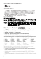
AP Mode Utility Configuration Figure 5-2. Configuration - Security Setting Country Region Code — Select the country region where the access point is in operation. Table 5-2. Country Channel List Classification 0: USA, Canada, Taiwan 1: Europe 2: Spain 3: France 4: Japan (MKK) 5: Japan (TELEC) 6: ISRAEL 7: ISRAEL Range CH 1 ~ CH 11 CH 1 ~ CH 13 CH 10 ~ CH 11 CH 10 ~ CH 13 CH 14 CH 1 ~ CH 14 CH 3 ~ CH 9 CH 5 ~ CH 13 Beacon (ms) — Set the time invterval between two beacons.
AP Mode Configuration Access Control The access control page allows you to restrict the MAC address connected to this AP. Figure 5-3. Access Control The displayed items on this page can be described as follows: Access Policy — Select a policy for access control. (Default: Disable) • Disable – Disable the feature. • Allow All – Allow the access for the listed MAC addresses. • Reject All – Deny the access for the listed MAC addresses. Mac Address — Input the MAC address applied this feature.
AP Mode Utility Configuration MAC Table The MAC table page displays the current station link information. Figure 5-4. MAC Table The displayed items on this page can be described as follows: MAC Address — The MAC addresses of the connected stations. AID — Raise value by the current wireless connection. Power Saving Mode — The power saving status of the connected station.
AP Mode Configuration Event Log The event log page displays system messages generated during system operation. The logged messages can serve as a valuable tool for isolating Wireless USB Adapter and network problems. Figure 5-5.
AP Mode Utility Configuration Statistics The statistics page displays the connected-related statistics with detail counter information. Click Reset Counters to reset all the items back to 0. Figure 5-6.
AP Mode Configuration About The about page displays the information about version numbers of the configuration utility, firmware and other information of the device. Click the WWW.SMC.COM button to visit the SMC website for other information. Figure 5-7.
AP Mode Utility Configuration Help The help page provides detailed information about each setting of the Soft AP utility. Click one of the headings to view the information. Figure 5-8. Help Screen Display If you want to switch the device back to the station mode, click the Soft AP utility icon with the right button of the mouse and then select Switch to Station Mode.
AP Mode Configuration 5-12
Appendix A: Troubleshooting USB Adapter Installation Problems If your computer cannot find the EZ Connect Wireless USB Adapter or the network driver does not install correctly, check the following items: • Make sure the adapter is connected to the USB port. Check for any hardware problems, such as physical damage to the adapter’s connector. • Try the adapter in another USB port. If this also fails, try using another SMCWUSBS-N wireless adapter that is known to operate correctly.
Troubleshooting Uninstalling the Utility If you are having problems with the utility, you may need to uninstall the software from the system. Follow these steps: 1. From the Windows Start menu, find the SMC EZ Connect N Utility uninstall option. Click to start the uninstall process. 2. Click Yes to uninstall the utility.
Uninstalling the Utility 3. Uninstallation begins. 4. When the uninstall is complete, click Finish to exit.
Troubleshooting A-4
Appendix B: Specifications Interface USB version 2.0 compliant Power +5V DC, 0.5A over USB connection Radio Specifications IEEE 802.11n (draft 2.0) IEEE 802.11b/g Frequency North America: 2.412 - 2.462 GHz Japan: 2.412 - 2.472 GHz Europe: 2.412 - 2.472 GHz Operating Channels North America Certification: FCC; Channel: 11 Japan Certification: JTAC; Channel: 14 Europe Certification: ETSI; Channel: 13 Data Rate Shifting 1, 2, 5.5, 6, 9, 11, 12, 18, 24, 36, 48, 54 Mbps 802.11n (draft 2.
Specifications Physical Size 82 x 26 x 11 mm (3.23 x 1.02 x 0.43 in.) Weight 16 g (0.
SMCWUSBS-N 20 Mason • Irvine, CA 92618 • Phn: 949-679-8000 • www.smc.