
User's Manual

Installation Manual IMN
TigerAccess™ EE
SMC7824M/VSW 5
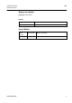
Illustrations
Fig. 1.1 Laser Symbol ...................................................................................................8
Fig. 2.1 Product View ..................................................................................................12
Fig. 2.2 Front Interfaces of the switch .........................................................................13
Fig. 2.3 LEDs of the Switch.........................................................................................16
Fig. 2.4 LEDs of the Option Uplink Modules ...............................................................18
Fig. 3.1 Grounding Symbol..........................................................................................19
Fig. 3.2 19” Rack (Sectional View)..............................................................................20
Fig. 3.3 19” Rack (Front View) ....................................................................................20
Fig. 3.4 Attaching the Rack Brackets ..........................................................................21
Fig. 3.5 Attaching the System to the Rack..................................................................21
Fig. 3.6 Attaching the Wall Mounting Brackets............................................................22
Fig. 3.7 The switch mounted on a wall........................................................................23
Fig. 3.8 Grounding the System ...................................................................................24
Fig. 4.1 Installing Uplink Option Modules....................................................................25
Fig. 5.1 Installing the Optical Connection with SFP Module .......................................27
Fig. 5.2 Connecting the GE-PON Interface.................................................................28
Fig. 5.3 RJ45 Connector .............................................................................................29
Fig. 5.4 Installing the Electrical Connection ................................................................29
Fig. 5.5 Connecting the VDSL Interface......................................................................30
Fig. 5.6 Connecting the Console Access ....................................................................32
Fig. 5.7 Connecting MGMT Interface ..........................................................................33
Fig. 5.8 Connecting the AC Power Cable....................................................................34