Installation Manual TigerAccess™ EE IMN Information furnished by SMC Networks, Inc. (SMC) is believed to be accurate and reliable. However, no responsibility is assumed by SMC for its use, nor for any infringements of patents or other rights of third parties which may result from its use. No license is granted by implication or otherwise under any patent or patent rights of SMC. SMC reserves the right to change specifications at any time without notice. Copyright (C) 2009 by SMC Networks, Inc.
IMN Installation Manual TigerAccess™ EE Warranty and Product Registration To register SMC products and to review the detailed warranty statement, please refer to the Support Section of the SMC Website at http://www.smc.
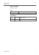
Installation Manual TigerAccess™ EE IMN Reason for Update Summary: Initial release Details: Chapter/Section Reason for Update All Initial release Issue History Issue Date of Issue Reason for Update 05/2009 Initial release Number 01 SMC7824M/VSW 3
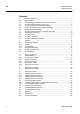
IMN Installation Manual TigerAccess™ EE Contents 4 1 1.1 1.2 1.3 1.4 1.5 1.6 1.7 1.8 1.9 1.10 1.11 Protective Measures ........................................................................................... 7 General Notes..................................................................................................... 7 Protection against Excessive High Contact Voltage........................................... 8 Protection against Escaping Laser Light ..........................................
Installation Manual TigerAccess™ EE IMN Illustrations Fig. 1.1 Fig. 2.1 Fig. 2.2 Fig. 2.3 Fig. 2.4 Fig. 3.1 Fig. 3.2 Fig. 3.3 Fig. 3.4 Fig. 3.5 Fig. 3.6 Fig. 3.7 Fig. 3.8 Fig. 4.1 Fig. 5.1 Fig. 5.2 Fig. 5.3 Fig. 5.4 Fig. 5.5 Fig. 5.6 Fig. 5.7 Fig. 5.8 SMC7824M/VSW Laser Symbol ...................................................................................................8 Product View ..................................................................................................
IMN Installation Manual TigerAccess™ EE Tables Tab. 2.1 Tab. 2.2 Tab. 2.3 Tab. 2.4 Tab. 2.5 Tab. 2.6 Tab. 2.7 Tab. 3.1 Tab. 5.1 Tab. 6.1 Tab. 6.2 Tab. 6.3 6 Front Access Interfaces of the switch............................................................ 13 Operating Status LEDs on the switch............................................................ 16 Status LEDs for VDSL Interfaces .................................................................. 17 Status LEDs on Console Interface ................
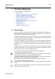
Installation Manual TigerAccess™ EE IMN 1 Protective Measures This section includes the following topics: • General Notes • Protection against Excessive High Contact Voltage • Protection against Escaping Laser Light • Protection against Fire in Racks or Housings • Components Subject to Electrostatic Discharge • Handling Modules (General) • Handling Optical Connectors and Fiber Optic Lines • Rack Mount Instructions • FCC Registration • UL Safety Compliance • Declaration of RoHS Conformity 1.
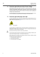
IMN Installation Manual TigerAccess™ EE 1.2 Protection against Excessive High Contact Voltage When dealing with the power supply or working on it, observe the provisions of VDE 0105 (operation of high-voltage equipment) Part 1, Section 9.3 (safety measures to be carried out) and the specifications of the European Norm EN 50110, Part 1 and Part 2 (Operation of electrical systems) at all times. Be sure to follow local national provisions regarding the handling of high-voltage equipment.
Installation Manual TigerAccess™ EE 1.4 IMN Protection against Fire in Racks or Housings If the system is used in housing, the system must comply with the conditions for fire protection housing according to DIN EN 60950-1. To comply with fire protection standards as defined in DIN EN 60950-1, a protective plate (C42165-A320-C684) must be fitted into the floor of ETSI and 19-inch standard racks. The rack must also meet the requirements of a fire-resistant housing as defined in DIN EN 60950-1. 1.
IMN Installation Manual TigerAccess™ EE ! There is a danger of injury if the door is left open. • • 1.7 When inserting and removing shelves and when transporting them, take their weight into consideration. Cables may never be disconnected by pulling on the cable. Disconnection/connection may only be undertaken by pushing in/pulling out the connector involved. Handling Optical Connectors and Fiber Optic Lines Optical connectors are precision components, and must be handled accordingly.
Installation Manual TigerAccess™ EE IMN This equipment has been tested and found to comply with the limits for a Class B digital device, pursuant to Part 15/68 of the FCC rules. These limits are designed to provide reasonable protection against harmful interference in a residential installation. This equipment generates, uses, and can radiate radio frequency energy and, if not installed and used in accordance with the instruction, may cause harmful interference to radio communications.
IMN Installation Manual TigerAccess™ EE 2 Overview SMC7824M/VSW is a 1.25U height single-board IP-DSLAM. It has been designed as compact-sized customer premise equipment for VDSL2 networks. The switch offers 24-Port VDSL2 service interface and fixed 2-Port 10/100/1000Base-T and 1-slot for option uplink module. The option module for uplink interface is also availale. NOTE – Module is not used in the first release.
Installation Manual TigerAccess™ EE IMN The interfaces of the switch are to find in Fig. 2.2 and Tab. 2.1. GTX Uplink Ports VDSL/POTS (1-24) Optional Expansion Slots Fig. 2.
IMN Installation Manual TigerAccess™ EE 2.1.2 Functionalities The switch provides the following functionalities: Advanced VDSL2 Function • • • • • • • • Configuration of xDSL line rate Provision of different band plans and profiles for xDSL interfaces VDSL2 interface according to ITU-T G.993.
Installation Manual TigerAccess™ EE IMN Security • • • • • • 802.1x MAC/port based authentication Storm control for broadcast, multicast and unknown unicast packets DoS protection Outband management IP source guard Secure Shell (SSH) Management • • • • • 2.1.3 Serial/Telnet (CLI) SNMPv1/v2/v3 Single IP management RMON sFlow Monitoring Physical Specification Mechanics Dimensions (W x H x D) Weight Heat transfer Air inlet Air outlet 440 mm x 55 mm x 310 mm 5.
IMN Installation Manual TigerAccess™ EE Power Supply AC power voltage Maximum power consumption 100-240VAC, 50/60Hz 85W (with 2-Port SFP option module) 88W (with 1-Port GE-PON + 1-Port SFP option module) Operating Indicators System LEDs VDSL i/f LEDs Uplink i/f LEDs RUN / FAN / PWR L/A L/A, 1G (1000Base-X, SFP) LNK (GE-PON) RX / TX LNK / ACT Console MGMT 2.2 Operating Status LEDs Fig. 2.
Installation Manual TigerAccess™ EE IMN Status LEDs for VDSL Interfaces Label 1-24 Tab. 2.3 Color Green Status Description On The interface is connected to a CPE. Blinking The interface is starting to be connected to a CPE. Off The interface is not connected to a CPE. Status LEDs for VDSL Interfaces Status LEDs for Console Interface Label TX RX Tab. 2.4 Color Green Green Status Description Blinking A transmit activity is present on the console.
IMN Installation Manual TigerAccess™ EE Fig. 2.4 LEDs of the Option Uplink Modules Status LEDs for Uplink Interfaces Label L/A Color Green 1G Amber Tab. 2.6 Status Description On/Blinking The interface is connected to a network. Off The interface is not connected to a network. On The transmit rate is 1 Gbps. Off The transmit rate is not 1 Gbps. Status LEDs for Uplink Interfaces Status LEDs for GE-PON Uplink Interfaces Label LNK Tab. 2.7 2.
Installation Manual TigerAccess™ EE IMN 3 Setting Up the Rack When setting up the rack, you must first install the rack and then the system. Refer to the assembly documents. 3.1 Rack Installation The switch is designed for indoor operation in the central office or collocation room with controlled environmental conditions. The network equipment is located in a central office. Each type of location is characterized by a typical technical infrastructure. Doors and rear panels are not provided.
IMN Installation Manual TigerAccess™ EE After the rack has been constructed, you can equip it. Fig. 3.2 19” Rack (Sectional View) 600 Fig. 3.3 20 2200 2000.25 (45U) 465.
Installation Manual TigerAccess™ EE 3.3 3.3.1 IMN Installing the System Equipping the Rack 1. Attach the rack brackets to the edge sides of the system as Fig. 3.4. Fig. 3.4 Attaching the Rack Brackets 2. Attach the system by inserting the cage nuts in the rack uprights in accordance with your rack configuring plan. Fig. 3.
IMN Installation Manual TigerAccess™ EE i 3.3.2 For equipping the system in ETSI rack, use the ETSI rack mount kit. Mounting on a Wall You can use the wall mounting brackets for mounting the switch on a wall. To mount the switch on a wall, follow these steps: 1. 2. 3. 4. Attach the wall mounting brackets to the edge sides of the system as Fig 3.6. Ensure that no electrical wires. Gas pipes or other utilities will be damaged by drilling. Mark the holes at the wall where the switch is to be installed.
Installation Manual TigerAccess™ EE IMN Fig. 3.
IMN Installation Manual TigerAccess™ EE 3.3.3 Grounding the System The system must always be grounded. Following grounding method is used for the switch: • i In a rack, as the only installation variant, the switch is grounded by screw connection with the grounded rack. Pay attention to strong screw connections. The system should be grounded with permanent connection to the protective earthing terminal. Fig. 3.
Installation Manual TigerAccess™ EE IMN 4 Equipping the System 4.1 Installing Uplink Module The switch provides the reserved slot for the uplink option module. The system will be delivered without the option module. When installing the uplink option module, note the followings: • When inserting the option module, observe the ESD requirements for protecting the units (see 1.5 Components Subject to Electrostatic Discharge).
IMN Installation Manual TigerAccess™ EE 5 Cabling the System Complete the following connections: 1. 2. 3. 4. 5.
Installation Manual TigerAccess™ EE 5.1 5.1.1 IMN Connecting Uplink Interface Installing Optical Connection The switch provides uplink 1-slot which requires its own additional optical module. You can select the proper module in Tab. 6.3. In this section, the case of installing an optical connection with the LC type SFP module is described. Use the following procedure when installing the optical connection with the LC type SFP module. 1. 2. 3. 4. 5. 6. 7.
IMN Installation Manual TigerAccess™ EE 5.1.2 Installing GE-PON Connection The switch provides 1-slot for an uplink module which has 1-port of 1000Base-X and 1port of GE-PON interface. Use the following procedure when installing the GE-PON connection on uplink modular unit. 1. 2. 3. 4. 5. 6. i Cut the cables to length. Attach the SC connectors. Label and mark the cables. Route and stow the cable in the rack. Install the cables according to your cabling plan. Connect the cable to the GE-PON interface.
Installation Manual TigerAccess™ EE 5.1.3 IMN Installing Electrical Connection According to the network or installation environment, you can use 10/100/1000Base-T interface instead of the optical connection. The switch automatically recognizes MDI/MDIX connectors defined in IEEE 802.3. Fig. 5.3 RJ45 Connector Use the following procedure when installing an electrical connection. 1. 2. 3. 4. 5. Cut the cables to length. Label and mark the cables. Route and stow the cable in the rack.
IMN Installation Manual TigerAccess™ EE 5.2 Connecting VDSL Interface The switch provides 24 VDSL ports as a subscriber interface. To enable broadband services to the subscriber, connect the copper cable to the Main Distribution Frame (MDF). 5.2.1 Connecting the System to the Main Distribution Frame Use this procedure when installing VDSL connections between the system and the MDF. Use the pre-assembled cables or adjust the cable lengths. 1. 2. 3. 4. 5. 6. Cut the cables to length.
Installation Manual TigerAccess™ EE 5.2.2 IMN Connecting Narrowband Services Use this procedure when connecting narrowband services. 1. 2. 3. 4. Cut the cables to length. Attach the connectors to the cables. Label and mark the cables. Install the cables to the POTS interfaces on the front panel of the switch in accordance with your cabling plan. 5. Route and stow the cable in the rack. 6. Connect the cables to the PSTN switch. Tab. 5.1 shows pin assignments for the RJ21 connectors.
IMN Installation Manual TigerAccess™ EE 5.3 Connecting Console Access The switch provides the console access to configure the system locally with command line interface (CLI). The RJ45-to-DB9 console cable will be delivered as a basic delivery package. 1. Connect DB9 connector of the supplied RJ45-to-DB9 console cable to the serial interface of the PC. 2. Connect RJ45 connector of the cable to the console interface on the front panel of the switch. Fig. 5.
Installation Manual TigerAccess™ EE 5.4 IMN Connecting MGMT Interface Use this procedure when connecting the 100Base-T outband MGMT interface. 1. 2. 3. 4. 5. Cut the cables to length. Attach the RJ45 connector to the cable. Label and mark the cables. Route and stow the cable with the RJ45 connector in the rack. Connect the cable to the MGMT interface on the front panel of the switch. Fig. 5.7 shows how to connect the outband MGMT interface. Fig. 5.
IMN Installation Manual TigerAccess™ EE 5.5 Connecting Power Supply To connect the operating voltage line to AC power supply and to the system: 1. Connect the provided AC power cable to AC power connector on the front panel of the switch. 2. Connect the other end of the power cable to AC power supply. Fig. 5.8 describes how to connect the AC power cable. Fig. 5.8 ! ! Connecting the AC Power Cable Make sure the power switch is in the OFF position before connecting.
Installation Manual TigerAccess™ EE IMN 6 Appendix A1 SMC7824M/VSW Abbreviations CE Communauté européenne, European Community CPE Customer Premises Equipment DSLAM Digital Subscriber Line Access Multiplexer EN European Norm ETSI European Telecommunications Standards Institute FE Fast Ethernet (100 Mbps) GE Gigabit Ethernet (1 Gbps) IEC International Electrotechnical Commission IEEE Institute of Electrical and Electronic Engineers IP Internet Protocol LED Light Emitting Diode MDF M
IMN Installation Manual TigerAccess™ EE A2 Ordering Information Bases Name Description SMC7824M/VSW IKANOS CO5 FX100100-5 + Marvell based system -. 100M Symmetric VDSL2 (All profile support) -. Fixed 24 port VDSL interface (RJ-21) -. Fixed 2-Port 10/100/1000Base-Tx uplink & 1-slot option module -. 600 Ohm POTS Splitter without billing tone. -. Fan : Fixed Type -. Front access with 1.25U height -. UL certification product -. SMC specific product / Silk: SMC Base Options Tab. 6.
Installation Manual TigerAccess™ EE SMC7824M/VSW IMN 37
FOR TECHNICAL SUPPORT, CALL: From U.S.A. and Canada (24 hours a day, 7 days a week) (800) SMC-4-YOU; (949) 679-8000; Fax: (949) 679-1481 From Europe: Contact details can be found on www.smc.com INTERNET E-mail addresses: techsupport@smc.com Driver updates: http://www.smc.com/index.cfm?action=tech_support_drivers_downloads World Wide Web: http://www.smc.com FOR LITERATURE OR ADVERTISING RESPONSE, CALL: U.S.A.