
Network Router User Manual


EX500 Serial System EX## - OME0008
- 8 -
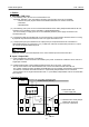
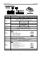
3 -2. Gateway ( GW ) Unit
Gateway ( GW ) Unit specification
Item Specification
Models EX500 - GAB1 - X1 EX500 - GDN1 EX500 - GPR1
Rated voltage 24V DC
Input and control power supply : 24V DC ±10%
Solenoid valve power supply : 24V DC +10% / -5%
( Warning of voltage drop given lower than approx. 20V )
Power supply
voltage
-
Communication power
supply for DeviceNet :
11V DC to 25V DC
-
200mA or less ( only GW Unit )
Current
consumption
-
Communication power
supply for DeviceNet :
50mA or less
-
Input / Output
points
Maximum 64 inputs / Maximum 64 outputs
Input / Output
branches
4 branches ( one branch 16 inputs / 16 outputs )
Branch
connector
M12 connector ( 8 pin, socket )
Pin NO.
1. RD + 2. RD -
3. TD + 4. TD -
5. 24V DC ( for solenoid valve)
6. 0V DC ( for solenoid valve)
7. 24V DC ( for power source )
8. 0V DC ( for power source )
Length of branch
cable
Less than 5m ( Less than 10m Max. Length )
Communication
form
Communication protocol : SMC original protocol
Communication speed : 750 k bit / sec. ( DeviceNet, PROFIBUS-DP )
: 500 k bit / sec. ( Remote I/O (RIO))
Power
Supply
connector
M12 connector ( 5 pin, plug )
Pin NO.
1. 0V ( for solenoid valve)
2. 24V DC + 10% / - 5% 3A Max.
( for solenoid valve)
3. 0V ( for power source ( input and control ) )
4. 24V DC±10% 3A Max.
( for power source ( input and control ) )
5. PE ( Protective earth )
Weight 470g
How to Order
EX500-GDN1
GW Unit compatible
Network communication
protocol
DN DeviceNet
Nil
DeviceNet
PR PROFIBUS-DP PROFIBUS-DP
AB Remote I/O ( RIO ) -X1 Remote I/O ( RIO )
R
C
U
S
T
Y
P
E
1
E
X
5
0
0
-
G
A
B
1
-
X
1
V
O
L
T
A
G
E
2
4
V
D
C
/
2
0
0
m
A
I
N
P
U
T
/
O
U
T
P
U
T
6
4
/
6
4
I
P
C
O
D
E
I
P
6
5
S
E
R
I
A
L
N
O
.
M
A
D
E
I
N
J
A
P
A
N
C
O
M
D
2
4
V
D
C
E
R
R
C
O
M
S
O
L
R
U
N
B
U
S
P
E
E
X
5
0
0
S
E
R
I
E
S
G
A
T
E
W
A
Y
U
N
I
T
S
M
C
S
M
C
S
M
C
S
M
C
.
Gateway ( GW ) Unit
For GW Unit
1
7
6
5
8
2
3
4
2
3
5
1
4
For GW Unit