
Network Router User Manual


EX500 Serial System EX## - OME0008
- 4 -
- INDEX -
1. Outline 6
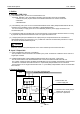
2. System Structure 6
3. Specification and Product numbers 7
3 -1 General specification of EX500 series 7
3 -2 Gateway ( GW ) Unit 8
3 -3 Input Unit Manifold 11
3 -3 -1 Input Manifold 11
3 -3 -2 Input Unit 11
3 -3 -3 Input Block 12
3 -4 SI Unit 13
3 -5 Applicable Manifold Valve series 13
3 -6 Option 14
3 -6 -1 Communication Connector / Cable 14
3 -6 -2 Branch Cable with M12 Connector 15
3 -6 -3 Power Supply Connector Cable 16
3 -6 -4 Terminal Plug 16
3 -6 -5 Water Proof Cap 16
4. How to operate EX500 - GAB1 - X1 ( Rockwell Automation Remote I/O ( RIO)) 17
4 -1 Applicable PLC 17
4 -2 Parts description 17
4 -3 LED display 18
4 -4 Operation setting 18
4 -4 -1 Operation setting switch ( SW1 ) 19
4 -4 -2 Operation setting switch ( SW2 ) 19
4 -4 -3 Terminating resistance setting switch ( SW3 ) 20
4 -5 Layout of scanner I/O 20
5. How to operate EX500 - GDN1 ( DeviceNet ) 21
5 -1 Connection style 21
5 -2 Parts description 22
5 -3 LED display 23
5 -4 Operation setting 23
5 -4 -1 Address setting switch ( SW1, 2 ) 24
5 -4 -2 Data rate setting switch ( SW3 ) 24
5 -5 I/O memory map 24
6. How to operate EX500 - GPR1 ( PROFIBUS - DP ) 25
6 -1 Communication wiring 25
6 -2 Parts description 25
6 -3 LED display 26
6 -4 Operation setting 26
6 -4 -1 Address setting switch ( SW1, 2, 3 ) 27
6 -4 -2 Terminating resistance setting switch ( SW4 ) 27
6 -5 I/O memory map 27