
Network Router User Manual


EX500 Serial System EX## - OME0008
- 31 -
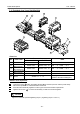
8. Manifold Valve
8 -1. Parts description
Refer to the Catalogues or Technical Instruction Manual of SV and VQC series Manifold Valve
for more details.
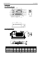
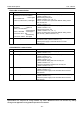
SV series
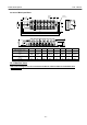
VQC series
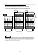
a. Communication connector : “C1“ or “0“ port … Input Unit is connected here.
“C2“ or “1“ port … GW Unit is connected here.
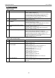
b. Power LED : Lights up when power source is ON.
Lights off when power source is OFF.
c. Communication LED : Lights up when receiving data from the GW Unit.
( communication ON )
Lights off when there is no communication from the GW Unit.
( communication OFF )
O
U
T
P
U
T
I
P
C
O
D
E
1
6
I
P
6
5
S
E
R
I
A
L
N
O
.
M
A
D
E
I
N
J
A
P
A
N
V
O
L
T
A
G
E
2
4
V
D
C
/
6
5
0
m
A
T
Y
P
E
1
E
X
5
0
0
-
S
0
0
1
R
C
U
S
C
O
M
P
W
R
C
1
C
2
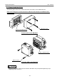
SI Unit for SV series Manifold
Communication connector ( C1 )
Communication connector ( C2 )
P
W
R
C
O
M
SV1000 series
Power LED
Communication LED
s
e
r
i
e
s
E
X
5
0
0
R
C
U
S
S
E
R
I
A
L
N
o
.
T
Y
P
E
1
M
A
D
E
I
N
J
A
P
A
N
S
I
U
N
I
T
E
X
5
0
0
-
Q
*
*
*
(
N
P
N
)
V
O
L
T
A
G
E
2
4
V
D
C
7
5
0
m
A
O
U
T
P
U
T
1
6
I
P
C
O
D
E
I
P
6
5
S
I
U
N
I
T
P
W
R
C
O
M
E
X
5
0
0
s
e
r
i
e
s
S
M
C
SI Unit for VQC series Manifold
Communication connector ( 0 )
Communication connector ( 1 )
Power LED
Communication LED
VQC1000 series