
Network Router User Manual


EX500 Serial System EX## - OME0008
- 30 -
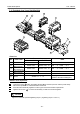
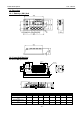
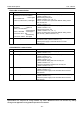
7 -3. Exploded view / Input Unit Manifold
・
・・
・Parts list
Parts number
NO. Parts name
For standard For RIO
Note
①
Input Unit EX500 - IB1 EX500 - IB1 -X1
②
Input Block
( M8 connector )
EX500 - IE□ EX500 - IE□ -X1 PNP … □: 1, NPN … □: 2
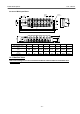
③
Input Block
( M12 connector )
EX500 - IE□ EX500 - IE□ -X1 PNP … □: 3, NPN … □: 4
④
8 point unit Input Block
( M8 connector )
EX500 - IE□ EX500 - IE□ -X1 PNP … □: 5, NPN … □: 6
⑤
End Block EX500 - EB1
⑥
DIN rail VZ1000 - 11 - 1 - □
□ : Length
( Refer to the Valve Catalogues )
・
・・
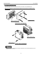
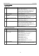
・Addition of the Input Block
1
Loose two screws a which are holding the End Block and the Input Unit until they rotate freely.
2
Add a new Input Block on a desired location on DIN rail.
3
Press the whole assembly together to make a good connection between Input Blocks.
4
Tight the two screws a to secure the assembly on DIN rail connected together.
Tight the screws with specified tightening torque. ( Tightening torque : 0.6 N・m )
M
A
D
E
I
N
J
A
P
A
N
R
C
U
S
T
Y
P
E
1
E
X
5
0
0
-
I
E
1
(
P
N
P
)
2
4
V
D
C
/
6
0
m
A
/
I
P
6
5
E
X
5
0
0
-
I
E
3
(
P
N
P
)
V
O
L
T
A
G
E
I
P
C
O
D
E
2
4
V
D
C
/
6
0
m
A
I
P
6
5
M
A
D
E
I
N
J
A
P
A
N
R
C
U
S
T
Y
P
E
1
M
A
D
E
I
N
J
A
P
A
N
R
C
U
S
T
Y
P
E
1
E
X
5
0
0
-
I
E
1
(
P
N
P
)
2
4
V
D
C
/
6
0
m
A
/
I
P
6
5
M
A
D
E
I
N
J
A
P
A
N
R
C
U
S
T
Y
P
E
1
E
X
5
0
0
-
I
E
1
(
P
N
P
)
2
4
V
D
C
/
6
0
m
A
/
I
P
6
5
T
Y
P
E
1
U
S
C
R
S
E
R
I
A
L
N
o
.
I
P
C
O
D
E
I
P
6
5
I
N
P
U
T
1
6
E
X
5
0
0
-
I
B
1
V
O
L
T
A
G
E
2
4
V
D
C
/
6
5
0
m
A
M
A
D
E
I
N
J
A
P
A
N
E
X
5
0
0
-
I
E
3
(
P
N
P
)
V
O
L
T
A
G
E
I
P
C
O
D
E
2
4
V
D
C
/
6
0
m
A
I
P
6
5
M
A
D
E
I
N
J
A
P
A
N
R
C
U
S
T
Y
P
E
1
E
X
5
0
0
-
I
E
3
(
P
N
P
)
V
O
L
T
A
G
E
I
P
C
O
D
E
2
4
V
D
C
/
6
0
m
A
I
P
6
5
M
A
D
E
I
N
J
A
P
A
N
R
C
U
S
T
Y
P
E
1
M
A
D
E
I
N
J
A
P
A
N
V
O
L
T
A
G
E
2
4
V
D
C
/
2
4
0
m
A
E
X
5
0
0
-
I
E
5
(
P
N
P
)
I
P
C
O
D
E
I
P
6
5
S
E
R
I
A
L
N
o
.
R
C
U
S
T
Y
P
E
1
1
a
2
3
5
a
6
4
!
!!
! CAUTION