
Network Router User Manual


EX500 Serial System EX## - OME0008
- 29 -
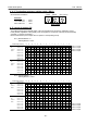
7. Input Unit Manifold
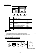
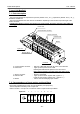
7 -1. Parts description
The Input Unit Manifold is composed of Input Unit ( EX500 - IB1 ( -X1 ) ), Input Block ( EX500 - IE□ ( -X1 ) ),
End Block and DIN rail.
The Input Unit Manifold can have various combinations depending on the number of input and type of the
sensor connector.
Input Block of different sensor specification can not be mixed. All blocks should be either PNP type
or NPN type.
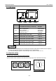
a. Communication connector : GW Unit or Manifold Valve with SI Unit is connected here.
b. Power LED : Lights up when power source is ON.
Flashing LED indicates the presence of a short circuit.
Power supply must be reset after fixing the short circuit.
Lights off when power source is OFF.
c. Sensor connector : Sensor is connected.
d. Indicator LED : Lights up when sensor signal is ON. ( logical “ 1 “ )
Lights off when sensor signal is OFF. ( logical “ 0 “ )
e. Marker : Can be used for identifying input number.
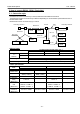
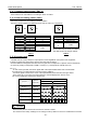
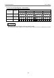
7 -2. Correspondence of input number and Input Block
Each Input Unit Manifold can have up to 8 Input Blocks (16 input points ).
The first Input Block is always next to Input Unit.
Refer to section 3 -3 for pin out of connectors used on Input Unit and Input Block.
M
A
D
E
I
N
J
A
P
A
N
R
C
U
S
T
Y
P
E
1
E
X
5
0
0
-
I
E
1
(
P
N
P
)
2
4
V
D
C
/
6
0
m
A
/
I
P
6
5
M
A
D
E
I
N
J
A
P
A
N
R
C
U
S
T
Y
P
E
1
E
X
5
0
0
-
I
E
1
(
P
N
P
)
2
4
V
D
C
/
6
0
m
A
/
I
P
6
5
M
A
D
E
I
N
J
A
P
A
N
R
C
U
S
T
Y
P
E
1
E
X
5
0
0
-
I
E
1
(
P
N
P
)
2
4
V
D
C
/
6
0
m
A
/
I
P
6
5
M
A
D
E
I
N
J
A
P
A
N
R
C
U
S
T
Y
P
E
1
E
X
5
0
0
-
I
E
1
(
P
N
P
)
2
4
V
D
C
/
6
0
m
A
/
I
P
6
5
M
A
D
E
I
N
J
A
P
A
N
R
C
U
S
T
Y
P
E
1
E
X
5
0
0
-
I
E
1
(
P
N
P
)
2
4
V
D
C
/
6
0
m
A
/
I
P
6
5
M
A
D
E
I
N
J
A
P
A
N
R
C
U
S
T
Y
P
E
1
E
X
5
0
0
-
I
E
1
(
P
N
P
)
2
4
V
D
C
/
6
0
m
A
/
I
P
6
5
M
A
D
E
I
N
J
A
P
A
N
R
C
U
S
T
Y
P
E
1
E
X
5
0
0
-
I
E
1
(
P
N
P
)
2
4
V
D
C
/
6
0
m
A
/
I
P
6
5
M
A
D
E
I
N
J
A
P
A
N
R
C
U
S
T
Y
P
E
1
E
X
5
0
0
-
I
E
1
(
P
N
P
)
2
4
V
D
C
/
6
0
m
A
/
I
P
6
5
T
Y
P
E
1
U
S
C
R
S
E
R
I
A
L
N
o
.
I
P
C
O
D
E
I
P
6
5
I
N
P
U
T
1
6
E
X
5
0
0
-
I
B
1
V
O
L
T
A
G
E
2
4
V
D
C
/
6
5
0
m
A
M
A
D
E
I
N
J
A
P
A
N
Indicator LED
Power LED
Communication connector
Sensor connector
Marker
Input Unit
M8 Input Block
End Block
In
p
ut Unit
1
0
7
6
5
4
3
2
9
8
11
10
13
12
15
14
1111 1111
0
0
0
0
0
0
0
0