
Network Router User Manual


EX500 Serial System EX## - OME0008
- 17 -
4. How to operate EX500 - GAB1 - X1 ( Rockwell Automation Remote I/O ( RIO))
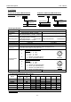
4 -1. Applicable PLC
Applicable PLCs in which Rockwell Automation Remote I/O ( RIO ) system is installed.
Please contact Rockwell Automation for more details.
・
・・
・Representative PLC
SLC500
PLC - 2 / 20 PLC - 2 / 30 PLC - 3 / 10
PLC - 5 / 11 PLC - 5 / 15 PLC - 5 / 20 PLC - 5 / 25
PLC - 5 / 30 PLC - 5 / 40 PLC - 5 / 40L PLC - 5 / 60
PLC - 5 / 60L PLC - 5 / 80
PLC - 5 / 250 PLC - 5 / VME PLC - 5 / V40B
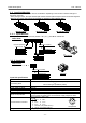
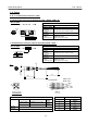
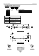
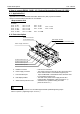
4 -2. Parts description
a. Fieldbus connector : Port for PLC connection.
b. Power supply connector : The power source for Input Unit, SI Unit, and control and
for the solenoid valve is connected through this port.
c. Communication port : Input Unit Manifold or the Manifold Valve with the SI Unit
is connected through this port.
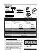
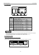
d. LED display window : The state of the power source supply and the PLC
communication is displayed. ( Refer to section 4 -3 )
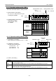
e. Station switch protection cover : Switches for the operation setting are inside.
( Refer to section 4 -4 )
The station switch protection cover should be tightened with specified tightening torque
after it is opened. ( Tightening torque : 0.6 N・m )
LED display window
Station switch protection cover
Communication port A
Communication port B
Communication port C
Communication port D
Power supply connector
Fieldbus connector
(1771 Remote I/O)
R
C
U
S
T
Y
P
E
1
E
X
5
0
0
-
G
A
B
1
-
X
1
V
O
L
T
A
G
E
2
4
V
D
C
/
2
0
0
m
A
I
N
P
U
T
/
O
U
T
P
U
T
6
4
/
6
4
I
P
C
O
D
E
I
P
6
5
S
E
R
I
A
L
N
O
.
M
A
D
E
I
N
J
A
P
A
N
C
O
M
D
2
4
V
D
C
E
R
R
C
O
M
S
O
L
R
U
N
B
U
S
P
E
E
X
5
0
0
S
E
R
I
E
S
G
A
T
E
W
A
Y
U
N
I
T
S
M
C
S
M
C
S
M
C
S
M
C
!
!!
! CAUTION