
Network Router User Manual


EX500 Serial System EX## - OME0008
- 12 -
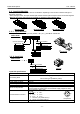
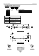
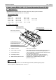
3 -3 -3. Input Block
Input Block specification
Item Specification
Corresponding sensor Current source type ( PNP output ) Current sink type ( NPN output )
Sensor connector
M8 connector ( 3 pin, socket )
Pin NO.
1. power supply (24V DC )
3. power supply ( 0V )
4. input
M12 connector ( 4 pin, socket )
Pin NO.
1. power supply (24V DC )
2. ( input ) *Note
3. power supply ( 0V )
4. input
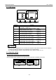
Input points 2 points / 8 points ( M8 only )
Rated voltage 24V DC
Logical ” 1 ” input voltage
15V to 26.4V 0V to 8V
Logical ” 0 ” input voltage
0V to 5V 19V to 26.4V
Logical ” 1 ” input current
5mA Typ. - 5mA Typ.
Logical ” 0 ” allowable current
1.5mA - 1.5mA
Input delay 1m sec. or less
Display LED ( green - colored ) light up
Insulation Nothing
Sensor supply current 30mA Max. / sensor
Weight [ M8 : 20g ] [ M12 : 40g ] [ 8 points ( M8) : 55g ]
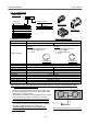
Note) Internal circuit of the M12 Input Block and the position of the key for installing the sensor
connector of the M12 Input Block.
Each No.2 pin of each sensor connector of the M12 Input
Block is connected to the next No.4 pin which is the sensor
signal input pin of the connector.
Therefore, it is possible to incorporate the two input signals
of the sensor into one cable. ( just like a Y connection )
Confirm the specification of the output signal when
connecting the sensor. It will cause the malfunction.
The position of the key for installing the sensor connector
of the M12 Input Block refers to the right figure.
Confirm the type of the sensor connector when
selecting a sensor.
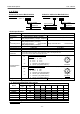
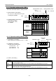
How to Order
EX5 00 - I E1
Connector type GW Unit compatible
Input specification
1 M8 connector, PNP
2 M8 connector, NPN
3 M12 connector, PNP
4 M12 connector, NPN
5 8 point unit, M8 connector, PNP
6 8 point unit, M8 connector, NPN
Nil
DeviceNet
PROFIBUS-DP
-X1 Remote I/O ( RIO )
1
4
3
For Input Block
1
4
2
3
For Input Block
M
A
D
E
I
N
J
A
P
A
N
R
C
U
S
T
Y
P
E
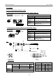
1
E
X
5
0
0
-
I
E
1
(
P
N
P
)
2
4
V
D
C
/
6
0
m
A
/
I
P
6
5
E
X
5
0
0
-
I
E
3
(
P
N
P
)
V
O
L
T
A
G
E
I
P
C
O
D
E
2
4
V
D
C
/
6
0
m
A
I
P
6
5
M
A
D
E
I
N
J
A
P
A
N
R
C
U
S
T
Y
P
E
1
M
A
D
E
I
N
J
A
P
A
N
V
O
L
T
A
G
E
2
4
V
D
C
/
2
4
0
m
A
E
X
5
0
0
-
I
E
5
(
P
N
P
)
I
P
C
O
D
E
I
P
6
5
S
E
R
I
A
L
N
o
.
R
C
U
S
T
Y
P
E
1
M8 Input Block
8 point unit Input Block ( M8 )
M12 Input Block
Figure of M12 Input Block ( the top of view )
1
0
Input “1” ( n + 1 )
Input “0” ( n )
Input “1” ( n + 1 ) side
1
4
2
3
Key
Input “0” ( n ) side
1
4
2
3
Key