NO.
EX500 Serial System EX## - OME0008 ● Safety Instructions ● ( Read carefully before handling. ) Thoroughly read this handling manual and related manuals mentioned here to ensure the safety and proper operation of the product. These safety instructions are intended to prevent hazardous situations and / or equipment damage. These instructions indicate the level of potential hazard by labeling “ CAUTION “ or “ WARNING“ .
EX500 Serial System EX## - OME0008 ! CAUTION 1. Read this manual thoroughly, and operate this product within the range of the specification after observing notes strictly. 2. Do not drop nor apply force to the product. It may damage the unit, and may cause failure or malfunction. 3. Take appropriate measures to ensure that the specified power is supplied regardless of the condition of power supply. Use within specified voltage range.
EX500 Serial System EX## - OME0008 ・Safety instructions for power supply ! CAUTION 1. Whether you use a single power supply or a dual power supply, two power lines have to be supplied at all times ( for solenoid valve and for input and control ). 2. Choose UL recognized product for direct current power source to be mounted.
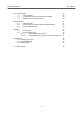
EX500 Serial System EX## - OME0008 - INDEX - 1. Outline 6 2. System Structure 6 3.
EX500 Serial System EX## - OME0008 7. Input Unit Manifold 7 -1 Parts description 7 -2 Correspondence of input number and Input Block 7 -3 Exploded view / Input Unit Manifold 29 29 29 30 8. Manifold Valve 8 -1 Parts description 8 -2 Correspondence of output number and Manifold Valve 8 -3 How to install the SI Unit 31 31 32 33 9. Wiring 9 -1 9 -2 34 34 35 35 35 Source wiring Communication wiring 9 -2 -1 Communication wiring to PLC 9 -2 -2 Communication wiring to the SI Unit and the Input Unit 10.
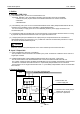
EX500 Serial System EX## - OME0008 1. Outline A. Gateway ( GW ) Unit ( 1 ) The Gateway ( GW ) Unit can be connected with a PLC. At present, Gateway ( GW ) Unit with the following communication protocols are available: ・ Remote I/O ( RIO ) System slaves to Rockwell Automation PLC and SLC series unit. ・ DeviceNet ・ PROFIBUS-DP ( 2 ) The Gateway ( GW ) Unit can be connected with Manifold Valve / Relay Output Module with the SI Unit, and Input Unit / Input Block can be controlled in a decentralized fashion.
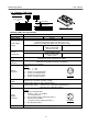
EX500 Serial System EX## - OME0008 3. Specification and Product numbers 3 -1. General specification of EX500 series Item Enclosure Standard Withstand voltage Specification IP65 UL,CSA,CE 1500V AC 1min. ( between PE - external terminal package ) 2MΩor more ( 500VDC meg. between PE - external terminal package ) 1m sec. or less +5℃ to +45℃ 35% to 85%RH ( without condensation ) - 25℃ to 70℃ 10Hz to 57Hz 0.
EX500 Serial System EX## - OME0008 3 -2. Gateway ( GW ) Unit How to Order E X 5 0 0 - G D N 1 BUS ER 24VD C RU SO N CO L M R EX GATE 500 WAY SE UNIT RIES SSMMC C -X1 GAB1 500- C COM D EX GW Unit compatible A 0m /20 VDC /64 24 64 E T AN TAG TPU IP65 JAP VOL /OU PUT E IN IN DE MAD CO IP L NO. RIA SE Network communication protocol TYPE1 US R DN DeviceNet Nil PR PROFIBUS-DP AB Remote I/O ( RIO ) -X1 PE DeviceNet PROFIBUS-DP .
EX500 Serial System EX## - OME0008 ・Communication specification for each PLC Rockwell Automation Remote I/O communication specification ( RIO ) ( EX500 - GAB1 - X1 ) Item Applicable PLC Communication speed Cable distance ( Terminating resistor size ) Communication connector Specification Rockwell Automation Remote I/O PLC 57.6 k bit / sec. , 115.2 k bit / sec. , 230.4 k bit / sec. 57.6 k bit / sec. : 3048 m [ 10000 feet ] ( 150Ω) 115.2 k bit / sec. : 1524 m [ 5000 feet ] ( 150Ω) 230.4 k bit / sec.
EX500 Serial System EX## - OME0008 PROFIBUS-DP communication specification ( EX500 - GPR1 ) Item Protocol Bus interface Communication speed Cable distance Freeze function Synchronous function ID number Communication connector Specification PROFIBUS-DP ( EN50170 ) EIA RS - 485 9.6 / 19.2 / 93.75 / 187.5 / 500 k bit / sec. 1.5 / 3 / 6 / 12 M bit / sec. Refer to section 6 -1 Available Available 1405 hex M12 connector ( 5 pin, plug ) IN OUT Pin NO. Pin NO. 1. VP 1. N.C. 2. RxD / TxD ( N ) 2.
EX500 Serial System EX## - OME0008 3 -3. Input Unit Manifold The Input Unit Manifold can have various combinations depending on the number of stations and type of the sensor connector. When placing an order, the input manifold part number and the input block part number are entered together. But only one sensor type has to be specified per manifold ( either NPN or PNP ). M8 Input Block M12 Input Block M8 and M12 mixed 3 -3 -1.
EX500 Serial System EX## - OME0008 3 -3 -3.
EX500 Serial System EX## - OME0008 3 -4. SI Unit SI Unit for SV series Manifold Valve SI Unit for VQC series Manifold Valve How to Order EX 5 0 0 - S 0 0 1 How to Order EX 5 0 0 - Q1 0 1 GW Unit compatible Nil -X1 GW Unit compatible DeviceNet Output specification PROFIBUS-DP 0 NPN output ( + COM. ) Remote I/O ( RIO ) Nil -X1 1 PNP output ( - COM.
EX500 Serial System EX## - OME0008 3 -6. Option 3 -6 -1. Communication Connector / Cable 1. Communication Connector for Remote I/O ( RIO ) ( EX500 - GAB1 -X1 ) How to Order E X 5 0 0 - AC 0 0 0 - AB 1 1 4 3 Contact resistance ( connector part ) Insulation resistance Withstand voltage ( connector part ) φ14.2 2 φ14.9 2× M1 Electric specification Rated voltage 125V DC Rated current 3A 43.
EX500 Serial System EX## - OME0008 3 -6 -2. Branch Cable with M12 Connector How to Order E X 5 0 0 - AC 0 3 0 - S S P S L : Cable length Connector specification 003 0.3m SSPS Socket side : Straight, Plug side : Straight 005 0.5m SAPA Socket side : Angled, Plug side : Angled 010 1m 030 3m 050 5m Electric specification Rated voltage 36V DC Rated current 1.
EX500 Serial System 3 -6 -3. EX## - OME0008 Power Supply Connector Cable Electric specification Rated voltage 125V DC Rated current 3A How to Order E X 5 0 0 - A P 0 5 0 - S L : Cable length 010 1m 050 5m Contact resistance ( connector part ) Insulation resistance Withstand voltage ( connector part ) Connector spesification S Straight A Angled ( At 20mV DC or less, 100mA or less ) 1000M ohms or more ( At 500V DC ) 1500V AC 1min. ( Leak current 1mA or less ) M12 φ6 φ14.9 28.
EX500 Serial System EX## - OME0008 4. How to operate EX500 - GAB1 - X1 ( Rockwell Automation Remote I/O ( RIO)) 4 -1. Applicable PLC Applicable PLCs in which Rockwell Automation Remote I/O ( RIO ) system is installed. Please contact Rockwell Automation for more details.
EX500 Serial System EX## - OME0008 4 -3.
EX500 Serial System EX## - OME0008 4 -4 -1. Operation setting switch ( SW1 ) RACK Address ( 6bit ) EX.) 111100b→74o This switch sets RACK Address / Starting Quarter. ( 1 ) RACK Address ( 6 bit setting ) 0 to 74 ( OCT : octal number ) 61 types of setting are available. ON ( 1 ) SW1 OFF ( 0 ) ( 2 ) Starting Quarter ( 2 bit setting ) Three types of setting ( First, Second, Third ) are available.
EX500 Serial System EX## - OME0008 4 -4 -3. Terminating resistance setting switch ( SW3 ) Set termination resistance. ①150Ω Data Rate 57.6 k bit / sec. : 150Ω 115.2 k bit / sec. : 150Ω 230.4 k bit / sec. : 82Ω ②82Ω ③No resistance State of SW3 4 -5. Layout of scanner I/O I/O mapping image at the Gateway (GW ) Unit communication port is shown in examples 1 and 2. In this product, regardless of the quantity of the I/O equipment, continuous 4 Groups are automatically occupied. ( 1/2 RACK occupation ).
EX500 Serial System EX## - OME0008 5. How to operate EX500 - GDN1 ( DeviceNet ) 5 -1. Connection style DeviceNet unit can be connected by T branch, Multi branch and Branch line branch. Total extension length of trunk and stay is different depending on communication speed and thickness of communication cable. EX500 series can be connected only by T branch. Terminating resistance T branch Multi branch Node Multi branch Main Terminating resistance Node Branch line branch Max.
EX500 Serial System EX## - OME0008 5 -2. Parts description Fieldbus connector (DeviceNet) LED display window Station switch protection cover Power supply connector BU S TES TED TM SM C GA EX5 TEWA Y 00 SER UNIT IES CO M D 1 US Communication port A Communication port B Communication port C Communication port D c. Communication port d. LED display window e. Station switch protection cover R a. Fieldbus connector b.
EX500 Serial System EX## - OME0008 5 -3.
EX500 Serial System EX## - OME0008 5 -4 -1. Address setting switch ( SW1, 2 ) These switches set node address. The setting is shown in Table 1. 5 -4 -2. Data rate setting switch ( SW3 ) This switch set data rate. The setting is shown in Table 2. The factory default address and data rate are 63 and 125 k bit / sec. respectively. X10 X1 SW1 SW3 SW2 SW1 0 0 0 SW2 0 1 2 | 6 6 SW3 0 1 2 3 | 9 NODE ADDRESS 0 1 2 | 63 3 4 | PGM 9 DATA RATE 125 k bit / sec. 250 k bit / sec. 500 k bit / sec.
EX500 Serial System EX## - OME0008 6. How to operate EX500 - GPR1 ( PROFIBUS-DP ) 6 -1. Communication wiring ・Cable specification A twisted pair cable with shield is used in the communication wiring of PROFIBUS- DP. A maximum length of cable depend on communication speed. The specification of cable length is based on TYPE A cable which has parameters shown below.
EX500 Serial System EX## - OME0008 6 -3.
EX500 Serial System EX## - OME0008 6 -4 -1. Address setting switch ( SW1, 2, 3 ) These switches set node address. The setting is shown in the following figure. The address per one segment can be set in 32 node in case of no Repeater used and is set a maximum of 126 node in case of a Repeater used. ON X100 1 X10 2 SW2 SW3 SW3 1 2 1 ON OFF N.C X1 SW1 SW2 SW1 0 | 9 0 | 9 0 6 -4 -2. Terminating resistance setting switch ( SW4 ) ①resistance This switch is to set the terminating resistance.
EX500 Serial System EX## - OME0008 ・In case of corresponding with “ Double Word “ ( m,n=0 - ) Branch connector Data ( 4 byte ) MSB LSB 7 0 COM A / COM B Byte (m) ( n+2, n+3 ) COM C / COM D Byte (m+4) : : : : Double Word ( n, n+1 ) Double Word 1 MSB 7 LSB 0 MSB 7 LSB 0 MSB 7 LSB 0 Byte (m+1) Byte (m+2) Byte (m+3) Byte (m+5) Byte (m+6) Byte (m+7) ! CAUTION Read carefully the user manual of PLC which is used as a master.
EX500 Serial System EX## - OME0008 7. Input Unit Manifold 7 -1. Parts description The Input Unit Manifold is composed of Input Unit ( EX500 - IB1 ( -X1 ) ), Input Block ( EX500 - IE□ ( -X1 ) ), End Block and DIN rail. The Input Unit Manifold can have various combinations depending on the number of input and type of the sensor connector. Input Block of different sensor specification can not be mixed. All blocks should be either PNP type or NPN type.
EX500 Serial System EX## - OME0008 7 -3. Exploded view / Input Unit Manifold 2 a 1 3 EX 50 24 VDC C 0-IE (P 1 /6 0m NP A/ ) IP 65 R US MA DE IN TY PE 1 JAPA N E VOL X5 0 IN TAG 0IPPUT E 24 IB1 VDC SERCOD /65 IALE 0m No.
EX500 Serial System EX## - OME0008 8. Manifold Valve 8 -1. Parts description Refer to the Catalogues or Technical Instruction Manual of SV and VQC series Manifold Valve for more details. SV series PW R CO M R PW Power LED Communication LED EX5 M CO C1 00 -S VO LT OU AG E TP IP UT 24VD C/65 SE RICODE 0m AL A NO .
EX500 Serial System EX## - OME0008 8 -2.Correspondence of output number and Manifold Valve The output number to the Manifold Valve of the SI Unit is shown in the following figure. The SI Unit has output of 16 points. In case of the Relay Output Module ( 1 output ), it becomes like the Single solenoid valve. In case of the Relay Output Module ( 2 output ), it becomes like the Double solenoid valve.
EX500 Serial System EX## - OME0008 8 -3. How to install the SI Unit The following figure shows how to install / remove the SI Unit with / from the Manifold Valve. Refer to the Catalogues or Technical Instruction Manual of SV and VQC series Manifold Valve for more details. M3×30 : 4 pcs. SUP / EXH Block Ass'y SI Unit for SV series Manifold EX 50 0 ries se SUP / EXH Block Ass'y M3×10 : 2 pcs.
EX500 Serial System EX## - OME0008 9. Wiring ! CAUTION Wire each cables after turning the power supply OFF. 9 -1. Source wiring Wiring from power supply to GW’s power supply connector is called Source wiring. ( Refer to section 4 -2, 5 -2, 6 -2 ) For pin out of this connector refer to section 3 -2. It is not necessary to supply power to SI Unit, Valve Manifold Block and Input Unit Manifold Block individually. Power to these units will be supplied from GW Unit’s power supply connector.
EX500 Serial System EX## - OME0008 9 -2. Communication wiring 9 -2 -1. Communication wiring to PLC A. Remote I/O ( EX500 - GAB1 -X1 ) communication wiring Remote I/O communication cable can be connected with any of the two M12, 4 pin connectors on GW Unit. ( Refer to section 4 -2 ) For pin out of M12 connector refer to section 3 -2.
EX500 Serial System EX## - OME0008 10. Dimension 10 -1. Gateway ( GW ) Unit 10 -2. Input Unit Manifold ・In case of M8 Input Block 47 ( Pitch ) P=12 21 DIN rail 35 49 5.5 8 31 EX500-IE1 (PNP) EX500-IB1 VOLTAGE INPUT IP CODE SERIAL NO.
EX500 Serial System EX## - OME0008 ・In case of M12 Input Block ( Pitch ) P=20 47 DIN rail 25 EX500-IB1 VOLTAGE INPUT IP CODE SERIAL NO.
EX500 Serial System EX## - OME0008 11. Trouble shooting ・Whole system NO. 1 2 3 Item The solenoid valve does not work. The solenoid valve does not work as in the program. The Power LED of the Input Unit is flashing. 4 Connecting sensor does not start signal. 5 COM A - D does not light. Remedies ・ Check the power supply for the solenoid valve is supplying 24VDC. ( Refer to section 9 -1 ) ・Check the Branch Cable with M12 Connector is properly connected with the SI Unit.
EX500 Serial System EX## - OME0008 ・DeviceNet communication NO. Item 1 The status of MS LED Operating in a normal condition : Green lights Recoverable fault ( Memory is abnormal ) : Red lights 2 The status of NS LED Not online : Lights off Online , Not Allocated : Green flashing Online , Allocated : Green lights Connection Time - Out : Red flashing Critical Link Failure : Red lights SOL LED lights off. 3 Remedies ・Check the signal line from PLC is properly connected.