EliteConnect™ Universal 2.4GHz/5GHz Wireless Dual-Band Outdoor Access Point/Bridge The easy way to make all your network connections 38 Tesla Irvine, CA 92618 Phone: (949) 679-8000 May 2005 Revision Number: R01 F1.1.2.
Copyright Information furnished by SMC Networks, Inc. (SMC) is believed to be accurate and reliable. However, no responsibility is assumed by SMC for its use, nor for any infringements of patents or other rights of third parties which may result from its use. No license is granted by implication or otherwise under any patent or patent rights of SMC. SMC reserves the right to change specifications at any time without notice. Copyright © 2005 by SMC Networks, Inc.
LIMITED WARRANTY Limited Warranty Statement: SMC Networks, Inc. (“SMC”) warrants its products to be free from defects in workmanship and materials, under normal use and service, for the applicable warranty term. All SMC products carry a standard 90-day limited warranty from the date of purchase from SMC or its Authorized Reseller. SMC may, at its own discretion, repair or replace any product not operating as warranted with a similar or functionally equivalent product, during the applicable warranty term.
LIMITED WARRANTY Customers are responsible for all shipping charges from their facility to SMC. SMC is responsible for return shipping charges from SMC to customer. WARRANTIES EXCLUSIVE: IF AN SMC PRODUCT DOES NOT OPERATE AS WARRANTED ABOVE, CUSTOMER’S SOLE REMEDY SHALL BE REPAIR OR REPLACEMENT OF THE PRODUCT IN QUESTION, AT SMC’S OPTION.
COMPLIANCES Federal Communication Commission Interference Statement This equipment has been tested and found to comply with the limits for a Class B digital device, pursuant to Part 15 of the FCC Rules. These limits are designed to provide reasonable protection against harmful interference in a residential installation.
COMPLIANCES Wireless 5 GHz Band Statements: As the SMC2888W access point/bridge can operate in the 5150-5250 MHz frequency band it is limited by the FCC, Industry Canada and some other countries to indoor use only so as to reduce the potential for harmful interference to co-channel Mobile Satellite systems. High power radars are allocated as primary users (meaning they have priority) of the 5250-5350 MHz and 5650-5850 MHz bands. These radars could cause interference and/or damage to the access point.
COMPLIANCES • This device employs a radar detection feature required for European Community operation in the 5 GHz band. This feature is automatically enabled when the country of operation is correctly configured for any European Community country. The presence of nearby radar operation may result in temporary interruption of operation of this device. The radar detection feature will automatically restart operation on a channel free of radar.
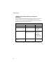
COMPLIANCES Operation Using 5 GHz Channels in the European Community The user/installer must use the provided configuration utility to check the current channel of operation and make necessary configuration changes to ensure operation occurs in conformance with European National spectrum usage laws as described below and elsewhere in this document. Allowed 5GHz Channels in Each European Community Country Allowed Frequency Bands Allowed Channel Numbers Countries 5.15 - 5.
COMPLIANCES Declaration of Conformity in Languages of the European Community English Hereby, SMC Networks, declares that this Radio LAN device is in compliance with the essential requirements and other relevant provisions of Directive 1999/5/EC. Finnish Valmistaja SMC Networks vakuuttaa täten että Radio LAN device tyyppinen laite on direktiivin 1999/5/EY oleellisten vaatimusten ja sitä koskevien direktiivin muiden ehtojen mukainen.
COMPLIANCES Italian Con la presente SMC Networks dichiara che questo Radio LAN device è conforme ai requisiti essenziali ed alle altre disposizioni pertinenti stabilite dalla direttiva 1999/5/CE.
COMPLIANCES Important! Before making connections, make sure you have the correct cord set. Check it (read the label on the cable) against the following: Power Cord Set U.S.A. and Canada The cord set must be UL-approved and CSA certified. The minimum specifications for the flexible cord are: - No. 18 AWG - not longer than 2 meters, or 16 AWG.
COMPLIANCES Veuillez lire à fond l'information de la sécurité suivante avant d'installer le wireless access point: AVERTISSEMENT: L’installation et la dépose de ce groupe doivent être confiés à un personnel qualifié. • Ne branchez pas votre appareil sur une prise secteur (alimentation électrique) lorsqu'il n'y a pas de connexion de mise à la terre (mise à la masse). • Vous devez raccorder ce groupe à une sortie mise à la terre (mise à la masse) afin de respecter les normes internationales de sécurité.
COMPLIANCES Cordon électrique - Il doit être agréé dans le pays d’utilisation Suisse: Europe La prise mâle d’alimentation doit respecter la norme SEV/ASE 1011. La prise secteur doit être conforme aux normes CEE 7/7 (“SCHUKO”) LE cordon secteur doit porter la mention ou et doit être de type HO3VVF3GO.75 (minimum).
COMPLIANCES gegeben, wenn auch die an das Gerät angeschlossenen Geräte unter SELV-Bedingungen betrieben werden. • Stromkabel. Dies muss von dem Land, in dem es benutzt wird geprüft werden: U.S.A und Kanada Der Cord muß das UL gepruft und war das CSA beglaubigt. Das Minimum spezifikation fur der Cord sind: - Nu. 18 AWG - nicht mehr als 2 meter, oder 16 AWG.
TABLE OF CONTENTS 1 Introduction . . . . . . . . . . . . . . . . . . . . . . . . . . . . . 1-1 Package Checklist . . . . . . . . . . . . . . . . . . . . . . . . . . . . . . . . . 1-2 Hardware Description . . . . . . . . . . . . . . . . . . . . . . . . . . . . . . . 1-4 Integrated High-Gain Antenna . . . . . . . . . . . . . . . . . . . . . 1-5 External Antenna Options . . . . . . . . . . . . . . . . . . . . . . . . 1-5 Ethernet Port . . . . . . . . . . . . . . . . . . . . . . . . . . . . . . . . . .
TABLE OF CONTENTS Connect External Antennas . . . . . . . . . . . . . . . . . . . . . . . . . . .4-5 Connect Cables to the Unit . . . . . . . . . . . . . . . . . . . . . . . . . . .4-7 Connect the Power Injector . . . . . . . . . . . . . . . . . . . . . . . . . . .4-7 Align Antennas . . . . . . . . . . . . . . . . . . . . . . . . . . . . . . . . . . . . .4-9 5 Initial Configuration . . . . . . . . . . . . . . . . . . . . . . . 5-1 Initial Setup through the CLI . . . . . . . . . . . . . . . . . . . . . . .
TABLE OF CONTENTS Entering Commands . . . . . . . . . . . . . . . . . . . . . . . . . . . . . . . . 7-3 Keywords and Arguments . . . . . . . . . . . . . . . . . . . . . . . . 7-3 Minimum Abbreviation . . . . . . . . . . . . . . . . . . . . . . . . . . . 7-3 Command Completion . . . . . . . . . . . . . . . . . . . . . . . . . . . 7-3 Getting Help on Commands . . . . . . . . . . . . . . . . . . . . . . . 7-4 Partial Keyword Lookup . . . . . . . . . . . . . . . . . . . . . . . . . .
TABLE OF CONTENTS System Clock Commands . . . . . . . . . . . . . . . . . . . . . . . . . . .7-28 sntp-server ip . . . . . . . . . . . . . . . . . . . . . . . . . . . . . . . . . .7-29 sntp-server enable . . . . . . . . . . . . . . . . . . . . . . . . . . . . . .7-30 sntp-server date-time . . . . . . . . . . . . . . . . . . . . . . . . . . .7-31 sntp-server daylight-saving . . . . . . . . . . . . . . . . . . . . . . .7-31 sntp-server timezone . . . . . . . . . . . . . . . . . . . . . . . . . . . .
TABLE OF CONTENTS WDS Commands . . . . . . . . . . . . . . . . . . . . . . . . . . . . . . . . . wds channel . . . . . . . . . . . . . . . . . . . . . . . . . . . . . . . . . . wds mac-address . . . . . . . . . . . . . . . . . . . . . . . . . . . . . . wds enable . . . . . . . . . . . . . . . . . . . . . . . . . . . . . . . . . . . show wds . . . . . . . . . . . . . . . . . . . . . . . . . . . . . . . . . . . . Bridge Commands . . . . . . . . . . . . . . . . . . . . . . . . . . . . . . . . bridge timeout .
TABLE OF CONTENTS dns server . . . . . . . . . . . . . . . . . . . . . . . . . . . . . . . . . . . .7-92 ip address . . . . . . . . . . . . . . . . . . . . . . . . . . . . . . . . . . . .7-93 ip dhcp . . . . . . . . . . . . . . . . . . . . . . . . . . . . . . . . . . . . . . .7-94 shutdown . . . . . . . . . . . . . . . . . . . . . . . . . . . . . . . . . . . . .7-95 show interface ethernet . . . . . . . . . . . . . . . . . . . . . . . . . .7-96 Wireless Interface Commands . . . . . . . . . . . . . . . . . .
TABLE OF CONTENTS A Troubleshooting . . . . . . . . . . . . . . . . . . . . . . . . . A-1 B Specifications . . . . . . . . . . . . . . . . . . . . . . . . . . . B-1 General Specifications . . . . . . . . . . . . . . . . . . . . . . . . . . . . . . B-1 Antenna Specifications . . . . . . . . . . . . . . . . . . . . . . . . . . . . . . B-4 17 dBi Integrated Panel . . . . . . . . . . . . . . . . . . . . . . . . . . B-4 C Cables and Pinouts . . . . . . . . . . . . . . . . . . . . . . .
TABLE OF CONTENTS xx
Chapter 1 Introduction The SMC EliteConnect Universal 2.4GHz/5GHz Wireless Dual-Band Outdoor Access Point/Bridge system consists of two models that provide point-to-point or point-to-multipoint bridge links between remote Ethernet LANs, and wireless access point services for clients in the local LAN area: • SMC2888W-S – Includes an integrated high-gain antenna for the 802.
Introduction In addition, both wireless bridge models offer full network management capabilities through an easy-to-use web interface, a command-line interface, and support for Simple Network Management Protocol (SNMP) tools. Radio Characteristics – The IEEE 802.11a and 802.11g standards use a radio modulation technique known as Orthogonal Frequency Division Multiplexing (OFDM), and a shared collision domain (CSMA/CA). The 802.
Package Checklist • Outdoor pole-mounting bracket kit • Outdoor wall-mounting bracket kit • This User Guide Inform your dealer if there are any incorrect, missing or damaged parts. If possible, retain the carton, including the original packing materials. Use them again to repack the product in case there is a need to return it.
Introduction Hardware Description Bottom View Ethernet Port RSSI Connector with Protective Cap Grounding Point Screw Integrated Antenna Top View (SMC2888W-S) N-Type External Antenna Connector (2.4 GHz) N-Type External Antenna Connector (2.4 GHz) Top View (SMC2888W-M) N-Type External Antenna Connector (2.
Hardware Description Integrated High-Gain Antenna The SMC2888W-S wireless bridge includes an integrated high-gain (17 dBi) flat-panel antenna for 5 GHz operation. External Antenna Options The SMC2888W-M Master bridge unit does not include an integrated antenna, but provides various external antenna options for both 5 GHz and 2.4 GHz operation.
Introduction Power Injector Module The wireless bridge receives power through its network cable connection using power-over-Ethernet technology. A power injector module is included in the wireless bridge package and provides two RJ-45 Ethernet ports, one for connecting to the wireless bridge (Output), and the other for connecting to a local LAN switch (Input). The Input port uses an MDI (i.e., internal straight-through) pin configuration.
Hardware Description The power injector module automatically adjusts to any AC voltage between 100-240 volts at 50 or 60 Hz. No voltage range settings are required. Warning: The power injector module is designed for indoor use only. Never mount the power injector outside with the wireless bridge unit. Receive Signal Strength Indicator (RSSI) BNC Connector The RSSI connector provides an output voltage that is proportional to the received radio signal strength.
Introduction System Configuration At each location where a unit is installed, it must be connected to the local network using the power injector module. The following figure illustrates the system component connections.
Features and Benefits Features and Benefits • SMC2888W-S Slave units support a 5 GHz high-gain 17 dBi antenna • SMC2888W-M Master units support 5 GHz point-to-multipoint links using various external antenna options • Both SMC2888W-S and SMC2888W-M units also support access point services for the 5 GHz and 2.4 GHz radios using various external antenna options • Maximum data rate up to 108 Mbps on the 802.11a (5 GHz) radio • Outdoor weatherproof design • IEEE 802.11a and 802.
Introduction System Defaults The following table lists some of the wireless bridge’s basic system defaults. To reset the bridge defaults, use the CLI command “reset configuration” from the Exec level prompt. Feature Parameter Default Identification System Name Dual Band Outdoor AP Administration User Name admin Password smcadmin HTTP Server Enabled HTTP Server Port 80 IP Address DHCP Subnet Mask 255.255.255.0 Default Gateway 0.0.0.0 Primary DNS IP 0.0.0.0 Secondary DNS IP 0.0.0.
System Defaults Feature Parameter Default SNMP Status Enabled Location null Contact Contact Community (Read Only) Public Community (Read/Write) Private Traps Enabled Trap Destination IP Address null Trap Destination Community Name Public System Logging Syslog Disabled Logging Host Disabled Logging Console Disabled IP Address / Host Name 0.0.0.
Introduction Feature Parameter Default Wireless Interface 802.11a Status Enabled SSID SMC Turbo Mode Disabled Radio Channel Default to first channel Auto Channel Select Enabled Transmit Power Full Wireless Security 802.
System Defaults Feature Parameter Default Wireless Interface 802.11b/g Status Enabled SSID SMC Radio Channel Default to first channel Auto Channel Select Enabled Transmit Power Full Wireless Security 802.
Introduction 1-14
Chapter 2 Network Configuration The Dual-band Outdoor Access Point / Bridge system provides access point or bridging services through either the 5 GHz or 2.4 GHz radio interfaces. The wireless bridge units can be used just as normal 802.11a/b/g access points connected to a local wired LAN, providing connectivity and roaming services for wireless clients in an outdoor area. Units can also be used purely as bridges connecting remote LANs.
Network Configuration The 802.11b and 802.11g frequency band, which operates at 2.4 GHz, can easily encounter interference from other 2.4 GHz devices, such as other 802.11b or g wireless devices, cordless phones and microwave ovens.
Access Point Topologies Infrastructure Wireless LAN The access point function of the wireless bridge provides access to a wired LAN for 802.11a/b/g wireless workstations. An integrated wired/wireless LAN is called an Infrastructure configuration. A Basic Service Set (BSS) consists of a group of wireless PC users and an access point that is directly connected to the wired LAN.
Network Configuration Infrastructure Wireless LAN for Roaming Wireless PCs The Basic Service Set (BSS) defines the communications domain for each access point and its associated wireless clients. The BSS ID is a 48-bit binary number based on the access point’s wireless MAC address, and is set automatically and transparently as clients associate with the access point. The BSS ID is used in frames sent between the access point and its clients to identify traffic in the service area.
Bridge Link Topologies Seamless Roaming for Wireless Clients Server Desktop PC Switch Notebook with Wireless PC Card Adapter Switch Access Point Notebook with Wireless PC Card Adapter Access Point PC with Wireless PCI Adapter Bridge Link Topologies The IEEE 802.11 standard defines a WIreless Distribution System (WDS) for bridge connections between BSS areas (access points). The outdoor wireless bridge uses WDS to forward traffic on links between units.
Network Configuration Note: The external antennas offer longer range options using the 5 GHz radio, which makes this interface more suitable for bridge links. When using WDS on a radio band, only wireless bridge units can associate to each other. Wireless clients can only associate with the wireless bridge using a radio band set to access point mode. Point-to-Point Configuration Two SMC2888W-S bridges can form a wireless point-to-point link using their 5 GHz (802.11a) integrated antennas.
Bridge Link Topologies Slave Slave Slave Master with Omnidirectional Antenna Slave Slave Slave Slave Master with Sector Antenna Slave Slave 2-7
Network Configuration 2-8
Chapter 3 Bridge Link Planning The SMC Dual-band Outdoor Access Point / Bridge supports fixed point-to-point or point-to-multipoint wireless links. A single link between two points can be used to connect a remote site to larger core network. Multiple bridge links can provide a way to connect widespread Ethernet LANs. For each link in a wireless bridge network to be reliable and provide optimum performance, some careful site planning is required.
Bridge Link Planning This area is known as the first Fresnel Zone of the radio link. For a radio link not to be affected by obstacles along its path, no object, including the ground, must intrude within 60% of the first Fresnel Zone. The following figure illustrates the concept of a good radio line-of-sight. Visual Line of Sight Radio Line of Sight If there are obstacles in the radio path, there may still be a radio link but the quality and strength of the signal will be affected.
Radio Path Planning • Be sure there is enough clearance from buildings and that no building construction may eventually block the path. • Check the topology of the land between the antennas using topographical maps, aerial photos, or even satellite image data (software packages are available that may include this information for your area). • Avoid a path that may incur temporary blockage due to the movement of cars, trains, or aircraft.
Bridge Link Planning . Total Link Distance Max Clearance for 60% of First Fresnel Zone at 5.8 GHz Approximate Clearance for Earth Curvature Total Clearance Required at Mid-point of Link 0.25 mile (402 m) 4.5 ft (1.4 m) 0 4.5 ft (1.4 m) 0.5 mile (805 m) 6.4 ft (1.95 m) 0 6.4 ft (1.95 m) 1 mile (1.6 km) 9 ft (2.7 m) 0 9 ft (2.7 m) 2 miles (3.2 km) 12.7 ft (3.9 m) 0 12.7 ft (3.9 m) 3 miles (4.8 km) 15.6 ft (4.8 m) 1.8 ft (0.5 m) 17.4 ft (5.3 m) 4 miles (6.4 km) 18 ft (5.5 m) 3.
Radio Path Planning A wireless bridge link is deployed to connect building A to a building B, which is located three miles (4.8 km) away. Mid-way between the two buidings is a small tree-covered hill. From the above table it can be seen that for a three-mile link, the object clearance required at the mid-point is 5.3 m (17.4 ft). The tree-tops on the hill are at an elevation of 17 m (56 ft), so the antennas at each end of the link need to be at least 22.3 m (73 ft) high.
Bridge Link Planning • The wireless bridge antennas at both ends of the link must be positioned with the same polarization direction, either horizontal or vertical Antenna Polarization — The wireless bridge’s integrated antenna sends a radio signal that is polarized in a particular direction. The antenna’s receive sensitivity is also higher for radio signals that have the same polarization. To maximize the performance of the wireless link, both antennas must be set to the same polarization direction.
Radio Path Planning Weather Conditions When planning wireless bridge links, you must take into account any extreme weather conditions that are known to affect your location. Consider these factors: • Temperature — The wireless bridge is tested for normal operation in temperatures from -33°C to 55°C. Operating in temperatures outside of this range may cause the unit to fail. • Wind Velocity — The wireless bridge can operate in winds up to 90 MPH and survive higher wind speeds up to 125 MPH.
Bridge Link Planning Ethernet Cabling When a suitable antenna location has been determined, you must plan a cable route form the wireless bridge outdoors to the power injector module indoors.
Chapter 4 Hardware Installation Before mounting antennas to set up your wireless bridge links, be sure you have selected appropriate locations for each antenna. Follow the guidance and information in Chapter 2, “Wireless Link Planning.” Also, before mounting units in their intended locations, you should first perform initial configuration and test the basic operation of the wireless bridge links in a controlled environment over a very short range.
Hardware Installation 5. Align antennas at both ends of the link. Testing Basic Link Operation Set up the units over a very short range (15 to 25 feet), either outdoors or indoors. Connect the units as indicated in this chapter and be sure to perform all the basic configuration tasks outlined above. When you are satisfied that the links are operating correctly, proceed to mount the units in their intended locations.
Mount the Unit Attach bracket to pole with mounting grooves facing up 3. Use the included nuts to tightly secure the wireless bridge to the bracket. Be sure to take account of the antenna polarization direction; both antennas in a link must be mounted with the same polarization.
Hardware Installation Mounting on Larger Diameter Poles In addition, there is a method for attaching the pole-mounting bracket to a pole that is 2 to 5 inches in diameter using an adjustable steel band clamp (not included in the kit). A steel band clamp up to 0.5 inch (1.27 cm) wide can be threaded through the main part of the bracket to secure it to a larger diameter pole without using the U-shaped part of the bracket. This method is illustrated in the following figure.
Connect External Antennas Mounting Grooves 2. Position the bracket in the intended location and mark the position of the three mounting screw holes. 3. Drill three holes in the wall that match the screws and wall plugs included in the bracket kit, then secure the bracket to the wall. 4. Use the included nuts to tightly secure the wireless bridge to the bracket.
Hardware Installation 2. Connect the antenna to the bridge’s N-type connector. 3. Apply weatherproofing tape to the antenna connectors to help prevent water entering the connectors. 2.4 GHz N-type Connector 5 GHz N-type Connector 5 GHz External High-gain Panel Antenna SMC2888W-M 2.
Connect Cables to the Unit Connect Cables to the Unit 1. Attach the Ethernet cable to the Ethernet port on the wireless bridge. Note: The Ethernet cable included with the package is 30 m (100 ft) long. To wire a longer cable (maximum 100 m, 325 ft), use the connector pinout information in Appendix B. 2. For extra protection against rain or moisture, apply weatherproofing tape (not included) around the Ethernet connector. 3.
Hardware Installation Note: The wireless bridge’s Ethernet port does not support Power over Ethernet (PoE) based on the IEEE 802.3af standard. Do not try to power the unit by connecting it directly to a network switch that provides IEEE 802.3af PoE. Always connect the unit to the included power injector module. 1. Connect the Ethernet cable from the wireless bridge to the RJ-45 port labeled “Output” on the power injector. 2.
Align Antennas 5. Check the LED on top of the power injector to be sure that power is being supplied to the wireless bridge through the Ethernet connection. Align Antennas After wireless bridge units have been mounted, connected, and their radios are operating, the antennas must be accurately aligned to ensure optimum performance on the bridge links. This alignment process is particularly important for long-range point-to-point links.
Hardware Installation strong central main lobe and smaller side lobes. The object of the alignment process is to set the antenna so that it is receiving the strongest signal from the central main lobe.
Align Antennas RSSI BNC Connection Voltmeter 2. Pan the antenna horizontally back and forth while checking the RSSI voltage. If using the pole-mounting bracket with the unit, you must rotate the mounting bracket around the pole. Other external antenna brackets may require a different horizontal adjustment. 3. Find the point where the signal is strongest (highest voltage) and secure the horizontal adjustment in that position.
Hardware Installation 4-12
Chapter 5 Initial Configuration The wireless bridge offers a variety of management options, including a web-based interface, a command line interface (CLI), or using SNMP management software. Most initial configuration steps can be made through the web browser interface using the Setup Wizard (page 5-4). However, for units that do not have a preset country code, you must first set the country code using the CLI. Note: Units sold in some countries are not configured with a specific country code.
Initial Configuration Initial Setup through the CLI The wireless bridge provides access to the CLI through a Telnet connection. You can open a Telnet session by performing these steps: 1. From the host computer, enter the Telnet command and the IP address of the wireless bridge unit (default 192.168.2.2 if not set via DHCP). 2. At the prompt, enter “admin” for the user name. 3. The default password is “smcadmin”.
Initial Setup through the CLI At the Exec prompt, type “country ?” to display the list of country codes. Check the code for your country, then enter the country command again followed by your country code (e.g., IE for Ireland). Dual Outdoor#country ie Dual Outdoor# Setting the IP Address – By default, the wireless bridge is configured to obtain IP address settings from a DHCP server. You may also use the CLI to assign an IP address that is compatible with your network.
Initial Configuration After configuring the wireless bridge’s IP parameters, you can access the management interface from anywhere within the attached network. The command line interface can also be accessed using Telnet from any computer attached to the network. Using the Web-based Management Setup Wizard There are only a few basic steps you need to complete to set up the wireless bridge for your network.
Using the Web-based Management Setup Wizard The home page displays the Main Menu. Launching the Setup Wizard – To perform initial configuration, click Setup Wizard on the home page, then click on the [Next] button to start the process. 1. Service Set ID – Enter the service set identifier in the SSID box which all wireless 802.11g clients must use to associate with the access point. The SSID is case sensitive and can consist of up to 32 alphanumeric characters (Default: SMC).
Initial Configuration 2. Radio Channel – You must enable radio communications for the 802.11a and 802.11g radios and set the operating channel. • 5-6 802.
Using the Web-based Management Setup Wizard Turbo Mode – If you select Enable, the wireless bridge will operate in turbo mode with a data rate of up to 108 Mbps. Normal mode supports 13 channels, Turbo mode supports only 5 channels. (Default: Disable) 802.11a Radio Channel – Set the operating radio channel number. (Default: 56ch, 5.280 GHz) Auto Channel Select – Select Enable to automatically select an unoccupied radio channel. (Default: Enable) • 802.11b/g 802.
Initial Configuration Note: Available channel settings are limited by local regulations which determine which channels are available. 3. IP Configuration – Either enable or disable (Dynamic Host Configuration Protocol (DHCP) for automatic IP configuration. If you disable DHCP, then manually enter the IP address and subnet mask. If a management station exists on another network segment, then you must enter the IP address for a gateway that can route traffic between these segments.
Using the Web-based Management Setup Wizard 4. WDS – To set up a wireless bridge link, you must configure the WDS forwarding table by specifying the Ethernet MAC address of the bridge to which you want to forward traffic. For a Slave bridge unit, you need to specify the MAC address of the wireless bridge unit at the opposite end of the link. For a Master bridge unit, you need to specify the MAC addresses of all the Slave bridge units in the network.
Initial Configuration 5. Security (802.11g) – Set the Authentication Type to “Open System” to allow open access without authentication, or “Shared Key” to require authentication based on a shared key. Enable Wired Equivalent Privacy (WEP) to encrypt data transmissions. To configure other security features use the Advanced Setup menu as described in Chapter 5.
Using the Web-based Management Setup Wizard hexadecimal or ASCII string of the appropriate length. The key can be entered as alphanumeric characters or hexadecimal (0~9, A~F, e.g., D7 0A 9C 7F E5). (Default: 128 bit, hexadecimal key type) 64-Bit Manual Entry: The key can contain 10 hexadecimal digits, or 5 alphanumeric characters. 128-Bit Manual Entry: The key can contain 26 hexadecimal digits or 13 alphanumeric characters.
Initial Configuration 5-12
Chapter 6 System Configuration Before continuing with advanced configuration, first complete the initial configuration steps described in Chapter 5 to set up an IP address for the wireless bridge. The wireless bridge can be managed by any computer using a web browser (Internet Explorer 5.0 or above, or Netscape Navigator 6.2 or above). Enter the default IP address: http:// 192.168.2.2 To log into the wireless bridge, enter the default user name “admin” and password “smcadmin” then click LOGIN.
System Configuration When the home page displays, click on Advanced Setup. The following page will display. The information in this chapter is organized to reflect the structure of the web screens for easy reference. However, it is recommended that you configure a user name and password as the first step under advanced configuration to control management access to the wireless bridge (page 6-33).
Advanced Configuration Advanced Configuration The Advanced Configuration pages include the following options.
System Configuration Menu RSSI Radio Interface A Description Page Controls the maximum RSSI voltage output 6-54 for specific WDS ports Configures the IEEE 802.11a interface 6-56 Radio Settings Configures radio signal parameters, such as 6-57 radio channel, transmission rate, and beacon settings Security Configures data encryption using Wired Equivalent Protection (WEP) or Wi-Fi Protected Access (WPA) 6-66 Configures the IEEE 802.
Advanced Configuration System Name – An alias for the wireless bridge, enabling the device to be uniquely identified on the network. (Default: Dual Band Outdoor AP; Range: 1-22 characters) Outdoor Bridge Band – Selects the radio band used for bridge links. • A – Bridging is supported on the 802.11a 5 GHz band. • G – Bridging is supported on the 802.11b/g 2.4 GHz band. • None – Bridging is not supported on either radio band. Allows both bands to support access point operations for wireless clients.
System Configuration CLI Commands for System Identification – Enter the global configuration mode and use the system name command to specify a new system name. Use the snmp-server location and snmp-server contact commands to indicate the physical location of the wireless bridge and define a system contact. Then return to the Exec mode, and use the show system command to display the changes to the system identification settings.
Advanced Configuration TCP / IP Settings Configuring the wireless bridge with an IP address expands your ability to manage the wireless bridge. A number of wireless bridge features depend on IP addressing to operate. Note: You can use the web browser interface to access IP addressing only if the wireless bridge already has an IP address that is reachable through your network.
System Configuration DHCP Client (Enable) – Select this option to obtain the IP settings for the wireless bridge from a DHCP (Dynamic Host Configuration Protocol) server. The IP address, subnet mask, default gateway, and Domain Name Server (DNS) address are dynamically assigned to the wireless bridge by the network DHCP server. (Default: Enabled) DHCP Client (Disable) – Select this option to manually configure a static address for the wireless bridge.
Advanced Configuration • Default Gateway: The default gateway is the IP address of the router for the wireless bridge, which is used if the requested destination address is not on the local subnet. • If you have management stations, DNS, or other network servers located on another subnet, type the IP address of the default gateway router in the text field provided. Otherwise, leave the address as all zeros (0.0.0.0).
System Configuration AP(config)#interface ethernet Enter Ethernet configuration commands, one per line. AP(if-ethernet)#no ip dhcp AP(if-ethernet)#ip address 192.168.1.2 255.255.255.0 192.168.1.253 AP(if-ethernet)#dns primary-server 192.168.1.55 AP(if-ethernet)#dns secondary-server 10.1.0.55 AP(config)#end AP#show interface ethernet Ethernet Interface Information ======================================== IP Address : 192.168.1.2 Subnet Mask : 255.255.255.0 Default Gateway : 192.168.1.253 Primary DNS : 192.
Advanced Configuration Primary Radius Server Setup – Configure the following settings to use RADIUS authentication on the access point. • IP Address: Specifies the IP address or host name of the RADIUS server. • Port: The UDP port number used by the RADIUS server for authentication messages.
System Configuration • Key: A shared text string used to encrypt messages between the access point and the RADIUS server. Be sure that the same text string is specified on the RADIUS server. Do not use blank spaces in the string. (Maximum length: 255 characters) • Timeout: Number of seconds the access point waits for a reply from the RADIUS server before resending a request.
Advanced Configuration to display the current settings for the primary and secondary RADIUS servers. AP(config)#radius-server AP(config)#radius-server AP(config)#radius-server AP(config)#radius-server AP(config)#radius-server AP(config)#exit AP#show radius address 192.168.1.25 port 181 key green timeout 10 retransmit 5 7-45 7-46 7-47 7-48 7-47 7-48 Radius Server Information ======================================== IP : 192.168.1.
System Configuration PPP over Ethernet – Enable PPPoE on the RJ-45 Ethernet interface to pass management traffic between the unit and a remote PPPoE server. (Default: Disable) PPPoE Username – The user name assigned for the PPPoE tunnel. (Range: 1-63 alphanumeric characters) PPPoE Password – The password assigned for the PPPoE tunnel. (Range: 1-63 alphanumeric characters) Confirm Password – Use this field to confirm the PPPoE password. PPPoE Service Name – The service name assigned for the PPPoE tunnel.
Advanced Configuration IP Allocation Mode – This field specifies how IP adresses for the PPPoE tunnel are configured on the RJ-45 interface. The allocation mode depends on the type of service provided by the PPPoE server. If automatic mode is selected, DHCP is used to allocate the IP addresses for the PPPoE connection. If static addresses have been assigned to you by the service provider, you must manually enter the assigned addresses.
System Configuration AP(config)#interface ethernet Enter Ethernet configuration commands, one per line. AP(if-ethernet)#ip pppoe AP(if-ethernet)#pppoe username mike AP(if-ethernet)#pppoe password 12345 AP(if-ethernet)#pppoe service-name classA AP(if-ethernet)#pppoe ip allocation mode static AP(if-ethernet)#pppoe local ip 10.7.1.200 AP(if-ethernet)#pppoe remote ip 192.168.1.
Advanced Configuration Ethernet Supplicant Setup – Allows the access point to act as an 802.1X supplicant so it can be authenticated through its Ethernet port with a RADIUS server on the local network. When enabled, a unique MD5 user name and password needs to be configured. (Default: Disabled) • Enabled/Disabled – Enables/Disables the 802.1X supplicant function. • Username – Specifies the MD5 user name. (Range: 1-22 characters) • Password – Specifies the MD5 password.
System Configuration . . . MAC Authentication – You can configure a list of the MAC addresses for wireless clients that are authorized to access the network. This provides a basic level of authentication for wireless clients attempting to gain access to the network. A database of authorized MAC addresses can be stored locally on the access point or remotely on a central RADIUS server.
Advanced Configuration Note: Client station MAC authentication occurs prior to the IEEE 802.1X authentication procedure configured for the access point. However, a client’s MAC address provides relatively weak user authentication, since MAC addresses can be easily captured and used by another station to break into the network. Using 802.1X provides more robust user authentication using user names and passwords or digital certificates.
System Configuration • Supported: The access point supports 802.1X authentication only for clients initiating the 802.1X authentication process (i.e., the access point does not initiate 802.1X authentication). For clients initiating 802.1X, only those successfully authenticated are allowed to access the network. For those clients not initiating 802.1X, access to the network is allowed after successful wireless association with the access point. • Required: The access point enforces 802.
Advanced Configuration . . . Local MAC Authentication – Configures the local MAC authentication database. The MAC database provides a mechanism to take certain actions based on a wireless client’s MAC address. The MAC list can be configured to allow or deny network access to specific clients. • • System Default: Specifies a default action for all unknown MAC addresses (that is, those not listed in the local MAC database).
System Configuration • • Permission: Select Allow to permit access or Deny to block access. If Delete is selected, the specified MAC address entry is removed from the database. • Update: Enters the specified MAC address and permission setting into the local database. MAC Authentication Table: Displays current entries in the local MAC database. CLI Commands for 802.1X Suppicant Configuration – Use the 802.
Advanced Configuration command. To display the current settings, use the show authentication command from the Exec mode.
System Configuration CLI Commands for RADIUS MAC Authentication – Use the mac-authentication server command from the global configuration mode to enable remote MAC authentication. Set the timeout value for re-authentication using the mac-authentication session-timeout command. Be sure to also configure connection settings for the RADIUS server (not shown in the following example). To display the current settings, use the show authentication command from the Exec mode.
Advanced Configuration CLI Commands for 802.1X Authentication – Use the 802.1X supported command from the global configuration mode to enable 802.1X authentication. Set the session and broadcast key refresh rate, and the re-authentication timeout. To display the current settings, use the show authentication command from the Exec mode. AP(config)#802.1X supported AP(config)#802.1X broadcast-key-refresh-rate 5 AP(config)#802.1X session-key-refresh-rate 5 AP(config)#802.
System Configuration Filter Control The wireless bridge can employ VLAN tagging support and network traffic frame filtering to control access to network resources and increase security. Native VLAN ID – The VLAN ID assigned to wireless clients that are not assigned to a specific VLAN by RADIUS server configuration. (Range: 1-64) VLAN – Enables or disables VLAN tagging support on the wireless bridge (changing the VLAN status forces a system reboot).
Advanced Configuration traffic that has an unknown VLAN ID or no VLAN tag is dropped. When VLAN support is disabled, the wireless bridge does not tag traffic passing to the wired network and ignores the VLAN tags on any received frames. Note: Before enabling VLANs on the wireless bridge, you must configure the connected LAN switch port to accept tagged VLAN packets with the wireless bridge’s native VLAN ID. Otherwise, connectivity to the wireless bridge will be lost when you enable the VLAN feature.
System Configuration Note: The specific configuration of RADIUS server software is beyond the scope of this guide. Refer to the documentation provided with the RADIUS server software. When VLAN filtering is enabled, the access point must also have 802.1X authentication enabled and a RADIUS server configured. Wireless clients must also support 802.1X client software to be assigned to a specific VLAN. When VLAN filtering is disabled, the access point ignores the VLAN tags on any received frames.
Advanced Configuration • Enable: Wireless bridge filters Ethernet protocol types based on the configuration of protocol types in the filter table. If a protocol has its status set to “ON,” the protocol is filtered from the wireless bridge. CLI Commands for VLAN Support – From the global configuration mode use the native-vlanid command to set the default VLAN ID for the Ethernet interface, then enable VLANs using the vlan enable command.
System Configuration you want to filter. To display the current settings, use the show filters command from the Exec mode.
Advanced Configuration SNMP – Enables or disables SNMP management access and also enables the wireless bridge to send SNMP traps (notifications). SNMP management is disabled by default. Community Name (Read Only) – Defines the SNMP community access string that has read-only access. Authorized management stations are only able to retrieve MIB objects.
System Configuration Trap Destination Community Name – The community string sent with the notification operation. (Maximum length: 23 characters; Default: public) CLI Commands for SNMP – Use the snmp-server enable server command from the global configuration mode to enable SNMP. To set read/write and read-only community names, use the snmp-server community command. The snmp-server host command defines a trap receiver host. To view the current SNMP settings, use the show snmp command.
Advanced Configuration Administration Changing the Password Management access to the web and CLI interface on the wireless bridge is controlled through a single user name and password. You can also gain additional access security by using control filters (see “Filter Control” on page 6-26). To protect access to the management interface, you need to configure an Administrator’s user name and password as soon as possible.
System Configuration CLI Commands for the User Name and Password – Use the username and password commands from the CLI configuration mode. AP(config)#username bob AP(config)#password spiderman AP# 7-19 7-20 Upgrading Firmware You can upgrade new wireless bridge software from a local file on the management workstation, or from an FTP or TFTP server. After upgrading new software, you must reboot the wireless bridge to implement the new code.
Advanced Configuration Before upgrading new software, verify that the wireless bridge is connected to the network and has been configured with a compatible IP address and subnet mask. If you need to download from an FTP or TFTP server, take the following additional steps: • Obtain the IP address of the FTP or TFTP server where the wireless bridge software is stored. • If upgrading from an FTP server, be sure that you have an account configured on the server with a user name and password.
System Configuration Firmware Upgrade Local – Downloads an operation code image file from the web management station to the wireless bridge using HTTP. Use the Browse button to locate the image file locally on the management station and click Start Upgrade to proceed. • New firmware file: Specifies the name of the code file on the server. The new firmware file name should not contain slashes (\ or /), the leading letter of the file name should not be a period (.
Advanced Configuration Note: If you have upgraded system software, then you must reboot the wireless bridge to implement the new operation code. CLI Commands for Downloading Software from a TFTP Server – Use the copy tftp file command from the Exec mode and then specify the file type, name, and IP address of the TFTP server. When the download is complete, the dir command can be used to check that the new file is present in the wireless bridge file system.
System Configuration System Log The wireless bridge can be configured to send event and error messages to a System Log Server. The system clock can also be synchronized with a time server, so that all the messages sent to the Syslog server are stamped with the correct time and date. Enabling System Logging The wireless bridge supports a logging process that can control error messages saved to memory or sent to a Syslog server.
Advanced Configuration Logging Console – Enables the logging of error messages to the console. Logging Level – Sets the minimum severity level for event logging. The system allows you to limit the messages that are logged by specifying a minimum severity level. The following table lists the error message levels from the most severe (Emergency) to least severe (Debug). The message levels that are logged include the specified minimum level up to the Emergency level.
System Configuration CLI Commands for System Logging – To enable logging on the wireless bridge, use the logging on command from the global configuration mode. The logging level command sets the minimum level of message to log. Use the logging console command to enable logging to the console. Use the logging host command to specify up to four Syslog servers. The CLI also allows the logging facility-type command to set the facility-type number to use on the Syslog server.
Advanced Configuration The wireless bridge acts as an SNTP client, periodically sending time synchronization requests to specific time servers. You can configure up to two time server IP addresses. The wireless bridge will attempt to poll each server in the configured sequence. SNTP Server – Configures the wireless bridge to operate as an SNTP client. When enabled, at least one time server IP address must be specified.
System Configuration CLI Commands for SNTP – To enable SNTP support on the wireless bridge, from the global configuration mode specify SNTP server IP addresses using the sntp-server ip command, then use the sntp-server enable command to enable the service. Use the sntp-server timezone command to set the location time zone and the sntp-server daylight-saving command to set up a daylight saving. To view the current SNTP settings, use the show sntp command. AP(config)#sntp-server ip 10.1.0.
Advanced Configuration Wireless Distribution System (WDS) The IEEE 802.11 standard defines a WIreless Distribution System (WDS) for connections between wireless bridges. The access point uses WDS to forward traffic on bridge links between units. When using WDS, only wireless bridge units can associate to each other using the bridge band. A wireless client cannot associate with the access point on the wireless bridge band.
System Configuration Mode – The wireless bridge is set to operate as a Slave or Master unit: • Master Mode: In a point-to-multipoint network configuration, only one wireless bridge unit must be a Master unit (all others must be Slave units). A Master wireless bridge provides support for up to 16 MAC addresses in the WDS forwarding table. The MAC addresses of all other Slave bridge units in the network must be configured in the forwarding table.
Advanced Configuration MAC Address – The physical layer address of the wireless bridge unit at the other end of the wireless link. (12 hexadecimal digits in the form “xx:xx:xx:xx:xx:xx”) Port Status – Enables or disables the wireless bridge link. Note: The Ethernet MAC address for each bridge unit is printed on the label on the back of the unit.
System Configuration Bridge Aging Time – Changes the aging time for entries in the dynamic address table: 6-46 • Ethernet: The time after which a learned Ethernet port entry is discarded. (Range: 60-1800 seconds; Default: 100 seconds) • Wireless 802.11a (g): The time after which a learned wireless entry is discarded.
Advanced Configuration CLI Commands for Bridging – The following example shows how to set the MAC address aging time for the wireless bridge. AP(config)#bridge timeout 0 300 AP(config)#bridge timeout 2 1000 AP(config)#exit AP#show bridge 7-66 7-66 7-75 Bridge Information ================================================= Media Type | Age Time(sec)| ================================================= EtherNet | 300 | WLAN_A | 1000 | ================================================== Bridge Id : 32768.
System Configuration device (except for the root device) which incurs the lowest path cost when forwarding a packet from that device to the root device. Then it selects a designated bridging device from each LAN which incurs the lowest path cost when forwarding a packet from that LAN to the root device. All ports connected to designated bridging devices are assigned as designated ports.
Advanced Configuration Enable – Enables/disables STP on the wireless bridge. (Default: Enabled) Forward Delay – The maximum time (in seconds) this device waits before changing states (i.e., discarding to learning to forwarding). This delay is required because every device must receive information about topology changes before it starts to forward frames.
System Configuration Hello Time – Interval (in seconds) at which the root device transmits a configuration message. (Range: 1-10 seconds) • Default: 2 • Minimum: 1 • Maximum: The lower of 10 or [(Max. Message Age / 2) -1] Maximum Age – The maximum time (in seconds) a device can wait without receiving a configuration message before attempting to reconfigure. All device ports (except for designated ports) should receive configuration messages at regular intervals.
Advanced Configuration assigned to ports with slower media. (Path cost takes precedence over port priority.) • Range: 1-65535 • Default: Ethernet interface: 19; Wireless interface: 40 Priority – Defines the priority used for this port in the Spanning Tree Protocol. If the path cost for all ports on a switch are the same, the port with the highest priority (i.e., lowest value) will be configured as an active link in the spanning tree.
System Configuration Port Fast (Fast Forwarding) – You can enable this option if an interface is attached to a LAN segment that is at the end of a bridged LAN or to an end node. Since end nodes cannot cause forwarding loops, they can pass directly through to the spanning tree forwarding state.
Advanced Configuration CLI Commands for STP – The following example configures spanning tree paramters for the bridge and wireless port 5.
System Configuration RSSI The RSSI value displayed on the RSSI page represents a signal to noise ratio. A value of 30 would indicate that the power of the received signal is 30 dBm above the signal noise threshold. This value can be used to align antennas (see page 4-9) and monitor the quality of the received signal for bridge links. An RSSI value of about 30 or more indicates a strong enough signal to support the maximum data rate of 54 Mbps.
Advanced Configuration RSSI – The RSSI value for a selected port can be displayed and a representative voltage output can be enabled. • Output Activate: Enables or disables the RSSI voltage output on the external RSSI connector. (Default: Enabled) • Port Number: Selects a specific WDS port for which to set the maximum RSSI output voltage level. Ports 1-16 are available for a Master unit, only port 1 for a Slave unit.
System Configuration Radio Interface The IEEE 802.11a and 802.11g interfaces include configuration options for radio signal characteristics and wireless security features. The configuration options are nearly identical, but depend on which interface is operating as the bridge band. Both interfaces and operating modes are covered in this section of the manual. The access point can operate in the following modes: • 802.11a in bridge mode and 802.11g in access point mode • 802.
Radio Interface Radio Settings A (802.11a) The IEEE 802.11a interface operates within the 5 GHz band, at up to 54 Mbps in normal mode or up to 108 Mbps in Turbo mode. Enable – Enables radio communications on the wireless interface. (Default: Enabled) Description – Adds a comment or description to the wireless interface. (Range: 1-80 characters) Network Name (SSID) – (Access point mode only) The name of the basic service set provided by the access point.
System Configuration mode. SSID Broadcast – When enabled, the access point radio does not include its SSID in beacon messages. Nor does it respond to probe requests from clients that do not include a fixed SSID. (Default: Disable) Turbo Mode – The normal 802.11a wireless operation mode provides connections up to 54 Mbps. Turbo Mode is an enhanced mode (not regulated in IEEE 802.11a) that provides a higher data rate of up to 108 Mbps.
Radio Interface Auto Channel Select – Enables the wireless bridge to automatically select an unoccupied radio channel. (Default: Enabled) Transmit Power – Adjusts the power of the radio signals transmitted from the wireless bridge. The higher the transmission power, the farther the transmission range. Power selection is not just a trade off between coverage area and maximum supported clients.
System Configuration Using higher DTIM values reduces the power used by stations in Power Save mode, but delays the transmission of broadcast/ multicast frames. (Range: 1-255 beacons; Default: 2 beacons) Fragment Length – Configures the minimum packet size that can be fragmented when passing through the wireless bridge. Fragmentation of the PDUs (Package Data Unit) can increase the reliability of transmissions because it increases the probability of a successful transmission due to smaller frame size.
Radio Interface Maximum Associations – (Access point mode only) Sets the maximum number of clients that can be associated with the access point radio at the same time. (Range: 1-64 per radio: Default: 64) CLI Commands for the 802.11a Wireless Interface – From the global configuration mode, enter the interface wireless a command to access the 802.11a radio interface. If required, configure a name for the interface using the description command.
System Configuration AP(config)#interface wireless a Enter Wireless configuration commands, one per line.
Radio Interface Radio Settings G (802.11g) The IEEE 802.11g standard operates within the 2.4 GHz band at up to 54 Mbps. Also note that because the IEEE 802.11g standard is an extension of the IEEE 802.11b standard, it allows clients with 802.11b wireless network cards to associate to an 802.11g access point. Enable – Enables radio communications on the access point. (Default: Enabled) Radio Channel – The radio channel that the access point uses to communicate with wireless clients.
System Configuration with each other. For example, in the United States you can deploy up to three access points in the same area (e.g., channels 1, 6, 11). Also note that the channel for wireless clients is automatically set to the same as that used by the access point to which it is linked. (Range: 1-11 (US/Canada); Default: 1) Auto Channel Select – Enables the access point to automatically select an unoccupied radio channel. (Default: Enabled) Working Mode – Selects the operating mode for the 802.
Radio Interface stop sending the SSID in beacon messages. Select a radio channel or set selection to Auto using the channel command. Set any other parameters as required. To view the current 802.11g radio settings, use the show interface wireless g command. AP(config)#interface wireless g Enter Wireless configuration commands, one per line.
System Configuration Security (Bridge Mode) Wired Equivalent Privacy (WEP) and Advanced Encryption Standard (AES) are implemented for security in bridge mode to prevent unauthorized access to network data. To secure bridge link data transmissions, enable WEP or AES encryption for the bridge radio and set at least one encryption key.
Radio Interface Setting up IEEE 802.11 Wired Equivalent Privacy (WEP) shared keys prevents unauthorized access to the wireless bridge network. Be sure to define at least one static WEP key for data encryption. Also, be sure that the WEP keys are the same for all bridge units in the wireless network. Data Encryption Setup – Enable or disable the wireless bridge to use either WEP or AES for data encryption.
System Configuration Advanced Encryption Standard (AES) AES has been designated by the National Institute of Standards and Technology as the successor to the Data Encryption Standard (DES) encryption algorithm, and will be used by the U.S. government for encrypting all sensitive, nonclassified information. Because of its strength, and resistance to attack, AES is also being incorporated as part of the 802.11 security standard.
Radio Interface Configuring AES encryption keys on the wireless bridge provides far more robust security than using WEP. Also, a unique AES key can be used for each bridge link in the wireless network, instead of all bridges sharing the same WEP keys. Data Encryption Setup – Enable or disable the wireless bridge to use either WEP or AES for data encryption. If AES encryption is selected and enabled, you must configure one encryption key for each wireless port link on the wireless bridge.
System Configuration command. To view the current security settings, use the show interface wireless a command. AP(config)#interface wireless a Enter Wireless configuration commands, one per line.
Radio Interface CLI Commands for AES Security – From the 802.11a interface configuration mode, use the encryption command to enable AES encryption. To enter AES keys, use the key command. To view the current security settings, use the show interface wireless a command. AP(config)#interface wireless a Enter Wireless configuration commands, one per line.
System Configuration Security (Access Point Mode) A radio band set to access point mode is configured by default as an “open system,” which broadcasts a beacon signal including the configured SSID. Wireless clients can read the SSID from the beacon, and automatically reset their SSID to allow immediate connection to the access point.
Radio Interface wireless clients. A summary of wireless security considerations is listed in the following table. Security Client Support Mechanism Implementation Considerations WEP Built-in support on all 802.11a and 802.11g devices • Provides only weak security • Requires manual key management WEP over 802.1X Requires 802.1X client • Provides dynamic key rotation for improved WEP security support in system or by add-in software • Requires configured RADIUS server (support provided in • 802.
System Configuration Note: Although a WEP static key is not needed for WEP over 802.1X, WPA over 802.1X, and WPA PSK modes, you must enable WEP encryption through the web or CLI in order to enable all types of encryption in the access point. Wired Equivalent Privacy (WEP) WEP provides a basic level of security, preventing unauthorized access to the network and encrypting data transmitted between wireless clients and the access point.
Radio Interface authentication and data encryption. Also, be sure that the WEP shared keys are the same for each client in the wireless network. Authentication Type Setup – Sets the access point to communicate as an open system that accepts network access attempts from any client, or with clients using pre-configured static shared keys. • Open System: Select this option if you plan to use WPA or 802.1X as a security mechanism.
System Configuration Shared Key Setup – Select 64 Bit, 128 Bit, or 152 Bit key length. Note that the same size of encryption key must be supported on all wireless clients. 152 Bit key length is only supported on 802.11a radio.
Radio Interface four settings without having to update the client keys. Note: Key index and type must match that configured on the clients. The configuration settings for WEP are summarized below: WEP only WEP over 802.1X Authentication Type: Shared Key Authentication Type: Open System WEP (encryption): Enable WEP (encryption): Enable WPA clients only: Disable WPA clients only: Disable Multicast Cipher: WEP Multicast Cipher: WEP Shared Key: 64/128/152 Shared Key: 64/128 Key Type - 802.
System Configuration show interface wireless a or show interface wireless g command. AP(config)#interface wireless g Enter Wireless configuration commands, one per line. AP(if-wireless g)#authentication shared AP(if-wireless g)#encryption 128 AP(if-wireless g)#multicast-cipher wep AP(if-wireless g)#key 1 128 ascii abcdeabcdeabc AP(if-wireless g)#transmit-key 1 AP(if-wireless g)#end AP(config)#no 802.
Radio Interface CLI Commands for WEP over 802.1X Security – From the 802.11a or 802.11g interface configuration mode, use the authentication command to select open system authentication. Use the multicast-cipher command to select WEP cipher type. Then set 802.1X to required with 802.1X command, and disable MAC authentication with the mac-authentication command. To view the current 802.11g security settings, use the show interface wireless g command (not shown in example).
System Configuration Wi-Fi Protected Access (WPA) WPA employs a combination of several technologies to provide an enhanced security solution for 802.11 wireless networks. The access point supports the following WPA components and features: IEEE 802.1X and the Extensible Authentication Protocol (EAP): WPA employs 802.1X as its basic framework for user authentication and dynamic key management. The 802.
Radio Interface when a RADIUS server has authenticated a user’s credentials will encryption keys be sent to the access point and client. Note: To implement WPA on wireless clients requires a WPA-enabled network card driver and 802.1X client software that supports the EAP authentication type that you want to use. Windows XP provides native WPA support, other systems require additional software. Temporal Key Integrity Protocol (TKIP): WPA specifies TKIP as the data encryption method to replace WEP.
System Configuration uses TKIP unicast data encryption keys for WPA clients and WEP unicast keys for WEP clients. The global encryption key for multicast and broadcast traffic must be the same for all clients, therefore it restricts encryption to a WEP key. When access is opened to both WPA and WEP clients, no authentication is provided for the WEP clients through shared keys. To support authentication for WEP clients in this mixed mode configuration, you can use either MAC authentication or 802.
Radio Interface The WPA configuration parameters are described below: Authentication Type Setup – When using WPA, set the access point to communicate as an open system to disable WEP keys. Note: Although WEP keys are not needed for WPA, you must enable WEP encryption through the web or CLI in order to enable all types of encryption in the access point. For example, set Wired Equivalent Privacy (WEP) Setup to “Enable” on the Security page.
System Configuration • TKIP: TKIP provides data encryption enhancements including per-packet key hashing (that is, changing the encryption key on each packet), a message integrity check, an extended initialization vector with sequencing rules, and a re-keying mechanism. • AES: AES has been designated by the National Institute of Standards and Technology as the successor to the Data Encryption Standard (DES) encryption algorithm, and will be used by the U.S.
Radio Interface The configuration settings for WPA are summarized below: WPA pre-shared key only WPA over 802.1X Authentication Type: Open System Authentication Type: Open System WEP (encryption): Enable1 WEP (encryption): Enable1 WPA clients only: Enable WPA clients only: Enable WPA Mode: Pre-shared-key WPA Mode: WPA over 802.1X 2 Multicast Cipher: WEP/TKIP/AES Multicast Cipher: WEP/TKIP/AES2 WPA PSK Type - Shared Key: 64/128/152 Hex: 64 characters 802.
System Configuration authentication. To view the current 802.11g security settings, use the show interface wireless a or show interface wireless g command (not shown in example). AP(config)#interface wireless g Enter Wireless configuration commands, one per line.
Status Information Status Information The Status page includes information on the following items: Menu Description Page AP Status Displays configuration settings for the basic system and the wireless interfaces 6-87 Station Status Shows wireless clients currently associated with the access point 6-90 Event Logs Shows log messages stored in memory 6-92 AP Status The AP Status window displays basic system configuration settings, as well as the settings for the wireless interfaces.
System Configuration • System Up Time: Length of time the management agent has been up. • MAC Address: The physical layer address for this device. • System Name: Name assigned to this system. • System Contact: Administrator responsible for the system. • IP Address: IP address of the management interface for this device. • IP Default Gateway: IP address of the gateway router between this device and management stations that exist on other network segments.
Status Information • Radio Authentication Type: Shows the bridge is set as an open system. • 802.1X: Shows if IEEE 802.1X access control for wireless clients is enabled. CLI Commands for Displaying System Settings – To view the current wireless bridge system settings, use the show system command from the Exec mode. To view the current radio interface settings, use the show interface wireless a command (see page 7-120).
System Configuration Station Status The Station Status window shows wireless clients currently associated with the access point. The Station Status page displays basic connection information for all associated stations. Note that this page is automatically refreshed every five seconds. 6-90 • Station Address: The MAC address of the remote wireless bridge. • Authenticated: Shows if the station has been authenticated. The two basic methods of authentication supported for 802.
Status Information • Associated: Shows if the station has been successfully associated with the access point. • Forwarding Allowed: Shows if the station has passed authentication and is now allowed to forward traffic. • Key Type: Displays one of the following: • Disabled: The client is not using Wired Equivalent Privacy (WEP) encryption keys. • Dynamic: The client is using Wi-Fi Protected Access (802.1X or pre-shared key mode) or using 802.1X authentication with dynamic keying.
System Configuration Event Logs The Event Logs window shows the log messages generated by the wireless bridge and stored in memory. The Event Logs table displays the following information: • Log Time: The time the log message was generated. • Event Level: The logging level associated with this message. For a description of the various levels, see “logging level” on page 6-38. • Event Message: The content of the log message.
Status Information 6-93
System Configuration 6-94
Chapter 7 Command Line Interface Using the Command Line Interface Accessing the CLI When accessing the management interface for the wireless bridge via a Telnet connection, the wireless bridge can be managed by entering command keywords and parameters at the prompt. Using the wireless bridge’s command-line interface (CLI) is very similar to entering commands on a UNIX system. Telnet Connection Telnet operates over the IP transport protocol.
Command Line Interface gateway if you are managing the wireless bridge from a different IP subnet. For example: AP#configure AP(config)#interface ethernet AP(if-ethernet)#ip address 10.1.0.1 255.255.255.0 10.1.0.254 AP(if-ethernet)# After you configure the wireless bridge with an IP address, you can open a Telnet session by performing these steps. 1. From the remote host, enter the Telnet command and the IP address of the device you want to access. 2. At the prompt, enter the user name and system password.
Entering Commands Entering Commands This section describes how to enter CLI commands. Keywords and Arguments A CLI command is a series of keywords and arguments. Keywords identify a command, and arguments specify configuration parameters. For example, in the command “show interface ethernet,” show and interface are keywords, and ethernet is an argument that specifies the interface type. You can enter commands as follows: • To enter a simple command, enter the command keyword.
Command Line Interface Getting Help on Commands You can display a brief description of the help system by entering the help command. You can also display command syntax by following a command with the “?” character to list keywords or parameters. Showing Commands If you enter a “?” at the command prompt, the system will display the first level of keywords for the current configuration mode (Exec, Global Configuration, or Interface). You can also display a list of valid keywords for a specific command.
Entering Commands The command “show interface ?” will display the following information: AP#show interface ? ethernet Show Ethernet interface wireless Show wireless interface AP#show interface Partial Keyword Lookup If you terminate a partial keyword with a question mark, alternatives that match the initial letters are provided. (Remember not to leave a space between the command and question mark.) For example “s?” shows all the keywords starting with “s.
Command Line Interface Understanding Command Modes The command set is divided into Exec and Configuration classes. Exec commands generally display information on system status or clear statistical counters. Configuration commands, on the other hand, modify interface parameters or enable certain functions. These classes are further divided into different modes. Available commands depend on the selected mode.
Entering Commands Configuration Commands Configuration commands are used to modify wireless bridge settings. These commands modify the running configuration and are saved in memory. The configuration commands are organized into three different modes: • Global Configuration - These commands modify the system level configuration, and include commands such as username and password.
Command Line Interface Command Line Processing Commands are not case sensitive. You can abbreviate commands and parameters as long as they contain enough letters to differentiate them from any other currently available commands or parameters. You can use the Tab key to complete partial commands, or enter a partial command followed by the “?” character to display a list of possible matches.
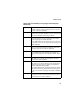
Command Groups Command Groups The system commands can be broken down into the functional groups shown below.
Command Line Interface Command Group Description Page IAPP Enables roaming between multi-vendor access points 7-122 VLANs Configures VLAN support 7-123 The access mode shown in the following tables is indicated by these abbreviations: GC (Global Configuration), IC-E (Ethernet Interface Configuration), and IC-W (Wireless Interface Configuration).
General Commands Command Mode Exec Example AP#configure AP(config)# Related Commands end (page 7-11) end This command returns to the previous configuration mode. Default Setting None Command Mode Global Configuration, Interface Configuration Example This example shows how to return to the Configuration mode from the Interface Configuration mode: AP(if-ethernet)#end AP(config)# exit This command returns to the Exec mode or exits the configuration program.
Command Line Interface Example This example shows how to return to the Exec mode from the Interface Configuration mode, and then quit the CLI session: AP(if-ethernet)#exit AP#exit CLI session with the wireless bridge is now closed Username: ping This command sends ICMP echo request packets to another node on the network. Syntax ping • host_name - Alias of the host. • ip_address - IP address of the host.
General Commands – Network or host unreachable - The gateway found no corresponding entry in the route table. • Press to stop pinging. Example AP#ping 10.1.0.19 192.168.1.19 is alive AP# reset This command restarts the system or restores the factory default settings. Syntax reset • board - Reboots the system. • configuration - Resets the configuration settings to the factory defaults, and then reboots the system.
Command Line Interface show history This command shows the contents of the command history buffer. Default Setting None Command Mode Exec Command Usage • The history buffer size is fixed at 10 commands. • Use the up or down arrow keys to scroll through the commands in the history buffer. Example In this example, the show history command lists the contents of the command history buffer: AP#show history config exit show history AP# show line This command displays the console port’s configuration settings.
System Management Commands Example The console port settings are fixed at the values shown below. AP#show line Console Line Information ====================================================== databits : 8 parity : none speed : 9600 stop bits : 1 ====================================================== AP# System Management Commands These commands are used to configure the user name, password, browser management options, and a variety of other system information.
Command Line Interface Command Function Mode Page ip http port Specifies the port to be used by the web browser interface GC 7-20 ip http server Allows the wireless bridge to be monitored or configured from a browser GC 7-21 show system Displays system information Exec 7-22 show version Displays version information for the system Exec 7-23 Web Server System Status country This command configures the wireless bridge’s country code, which identifies the country of operation and sets the
System Management Commands Country Code Country Code Country Code Belize BZ Hong Kong HK Monaco MC Syria SY Bolivia BO Hungary HU Morocco MA Taiwan TW Brazil BR Iceland IS Netherlands NL Thailand TH India IN New Zealand NZ Turkey TR Brunei BN Darussalam Code Country Bulgaria BG Indonesia ID Norway NO Ukraine UA Canada CA Iran IR Oman OM United Arab Emirates AE Chile CL Ireland IE Pakistan PK United Kingdom GB China CN Israel IL Panama PA Unite
Command Line Interface Example AP#country us AP# prompt This command customizes the CLI prompt. Use the no form to restore the default prompt. Syntax prompt string no prompt string - Any alphanumeric string to use for the CLI prompt.
System Management Commands system name This command specifies or modifies the system name for this device. Use the no form to restore the default system name. Syntax system name name no system name name - The name of this host. (Maximum length: 32 characters) Default Setting Outdoor Bridge Command Mode Global Configuration Example AP(config)#system name bridge-link AP(config)# username This command configures the user name for management access. Syntax username name name - The name of the user.
Command Line Interface Example AP(config)#username bob AP(config)# password After initially logging onto the system, you should set the password. Remember to record it in a safe place. Use the no form to reset the default password. Syntax password password no password password - Password for management access.
System Management Commands Default Setting 80 Command Mode Global Configuration Example AP(config)#ip http port 1143 AP(config)# Related Commands ip http server (page 7-21) ip http server This command allows this device to be monitored or configured from a browser. Use the no form to disable this function.
Command Line Interface show system This command displays basic system configuration settings. Default Setting None Command Mode Exec Example AP#show system System Information ========================================================= Serial Number : 0000000000 System Up time : 0 days, 0 hours, 17 minutes, 2 seconds System Name : Dual Band Outdoor AP System Location : System Contact : Contact System Country Code : TW - TAIWAN MAC Address : 00-03-7F-E0-06-EA IP Address : 192.168.2.2 Subnet Mask : 255.255.255.
System Logging Commands show version This command displays the software version for the system. Default Setting None Command Mode Exec Example AP#show version Version v1.1.2.1B05 AP# System Logging Commands These commands are used to configure system logging on the wireless bridge.
Command Line Interface logging on This command controls logging of error messages; i.e., sending debug or error messages to memory. The no form disables the logging process. Syntax logging on no logging on Default Setting None Command Mode Global Configuration Command Usage The logging process controls error messages saved to memory. You can use the logging level command to control the type of error messages that are stored in memory.
System Logging Commands Default Setting None Command Mode Global Configuration Example AP(config)#logging host 10.1.0.3 AP(config)# logging console This command initiates logging of error messages to the console. Use the no form to disable logging to the console. Syntax logging console no logging console Default Setting Disabled Command Mode Global Configuration Example AP(config)#logging console AP(config)# logging level This command sets the minimum severity level for event logging.
Command Line Interface Default Setting Error Command Mode Global Configuration Command Usage Messages sent include the selected level down to the Emergency level. Level Argument Description Emergency System unusable Alert Immediate action needed Critical Critical conditions (e.g., memory allocation, or free memory error - resource exhausted) Error Error conditions (e.g., invalid input, default used) Warning Warning conditions (e.g.
System Logging Commands Default Setting 16 Command Mode Global Configuration Command Usage The command specifies the facility type tag sent in syslog messages. (See RFC 3164.) This type has no effect on the kind of messages reported by the wireless bridge. However, it may be used by the syslog server to sort messages or to store messages in the corresponding database. Example AP(config)#logging facility 19 AP(config)# show logging This command displays the logging configuration.
Command Line Interface Example AP#show logging Logging Information ============================================ Syslog State : Disabled Logging Host State : Enabled Logging Console State : Disabled Server Domain name/IP : none Logging Level : Error Logging Facility Type : 16 ============================================= AP# System Clock Commands These commands are used to configure SNTP and system clock settings on the wireless bridge.
System Clock Commands sntp-server ip This command sets the IP address of the servers to which SNTP time requests are issued. Use the this command with no arguments to clear all time servers from the current list. Syntax sntp-server ip <1 | 2> • 1 - First time server. • 2 - Second time server. • ip - IP address of an time server (NTP or SNTP). Default Setting 137.92.140.80 192.43.244.
Command Line Interface sntp-server enable This command enables SNTP client requests for time synchronization with NTP or SNTP time servers specified by the sntp-server ip command. Use the no form to disable SNTP client requests. Syntax sntp-server enable no sntp-server enable Default Setting Disabled Command Mode Global Configuration Command Usage The time acquired from time servers is used to record accurate dates and times for log events.
System Clock Commands sntp-server date-time This command sets the system clock. Default Setting 00:14:00, January 1, 1970 Command Mode Global Configuration Example This example sets the system clock to 17:37 June 19, 2003. AP#sntp-server date-time Enter Year<1970-2100>: 2003 Enter Month<1-12>: 6 Enter Day<1-31>: 19 Enter Hour<0-23>: 17 Enter Min<0-59>: 37 AP# Related Commands sntp-server enable (page 7-30) sntp-server daylight-saving This command sets the start and end dates for daylight savings time.
Command Line Interface Command Usage The command sets the system clock back one hour during the specified period. Example This sets daylight savings time to be used from July 1st to September 1st. AP(config)#sntp-server daylight-saving Enter Daylight saving from which month<1-12>: 6 and which day<1-31>: 1 Enter Daylight saving end to which month<1-12>: 9 and which day<1-31>: 1 AP(config)# sntp-server timezone This command sets the time zone for the wireless bridge’s internal clock.
System Clock Commands degrees longitude. To display a time corresponding to your local time, you must indicate the number of hours and minutes your time zone is east (before) or west (after) of UTC. Example AP(config)#sntp-server timezone +8 AP(config)# show sntp This command displays the current time and configuration settings for the SNTP client.
Command Line Interface SNMP Commands Controls access to this wireless bridge from management stations using the Simple Network Management Protocol (SNMP), as well as the hosts that will receive trap messages.
SNMP Commands Default Setting • public - Read-only access. Authorized management stations are only able to retrieve MIB objects. • private - Read/write access. Authorized management stations are able to both retrieve and modify MIB objects. Command Mode Global Configuration Command Usage If you enter a community string without the ro or rw option, the default is read only. Example AP(config)#snmp-server community alpha rw AP(config)# snmp-server contact This command sets the system contact string.
Command Line Interface Example AP(config)#snmp-server contact Paul AP(config)# Related Commands snmp-server location (page 7-38) snmp-server enable server This command enables SNMP management access and also enables this device to send SNMP traps (i.e., notifications). Use the no form to disable SNMP service and trap messages.
SNMP Commands snmp-server host This command specifies the recipient of an SNMP notification. Use the no form to remove the specified host. Syntax snmp-server host no snmp-server host • host_ip_address - IP of the host (the targeted recipient). • host_name - Name of the host. (Range: 1-20 characters) • community-string - Password-like community string sent with the notification operation.
Command Line Interface Example AP(config)#snmp-server host 10.1.19.23 batman AP(config)# Related Commands snmp-server enable server (page 7-36) snmp-server location This command sets the system location string. Use the no form to remove the location string. Syntax snmp-server location text no snmp-server location text - String that describes the system location.
Flash/File Commands show snmp This command displays the SNMP configuration settings. Command Mode Exec Example AP#show snmp SNMP Information ============================================ Service State : Enable Community (ro) : ***** Community (rw) : ***** Location : WC-19 Contact : Paul Traps : Enabled Host Name/IP : 10.1.19.23 Trap Community : ***** ============================================= AP# Flash/File Commands These commands are used to manage the system code or configuration files.
Command Line Interface bootfile This command specifies the image used to start up the system. Syntax bootfile filename - Name of the image file. Default Setting None Command Mode Exec Command Usage • The file name should not contain slashes (\ or /), the leading letter of the file name should not be a period (.), and the maximum length for file names is 32 characters. (Valid characters: A-Z, a-z, 0-9, “.”, “-”, “_”) • If the file contains an error, it cannot be set as the default file.
Flash/File Commands copy This command copies a boot file, code image, or configuration file between the wireless bridge’s flash memory and a FTP/TFTP server. When you save the configuration settings to a file on a FTP/TFTP server, that file can later be downloaded to the wireless bridge to restore system operation. The success of the file transfer depends on the accessibility of the FTP/TFTP server and the quality of the network connection.
Command Line Interface • The destination file name should not contain slashes (\ or /), the leading letter of the file name should not be a period (.), and the maximum length for file names on the FTP/TFTP server is 255 characters or 32 characters for files on the wireless bridge. (Valid characters: A-Z, a-z, 0-9, “.”, “-”, “_”) • Due to the size limit of the flash memory, the wireless bridge supports only two operation code files. • The system configuration file must be named “syscfg” in all copy commands.
Flash/File Commands Default Setting None Command Mode Exec Caution: Beware of deleting application images from flash memory. At least one application image is required in order to boot the wireless bridge. If there are multiple image files in flash memory, and the one used to boot the wireless bridge is deleted, be sure you first use the bootfile command to update the application image file booted at startup before you reboot the wireless bridge. Example This example shows how to delete the test.
Command Line Interface Command Usage File information is shown below: Column Heading Description File Name The name of the file. Type (2) Operation Code and (5) Configuration file File Size The length of the file in bytes. Example The following example shows how to display all file information: AP#dir apimg1 zz-img.bin dflt-img.bin ap3xart.sys syscfg_bak syscfg apcfg zz-imgf.bin apcfg.
RADIUS Client RADIUS Client Remote Authentication Dial-in User Service (RADIUS) is a logon authentication protocol that uses software running on a central server to control access for RADIUS-aware devices to the network. An authentication server contains a database of credentials, such as users names and passwords, for each wireless client that requires access to the access point.
Command Line Interface Command Mode Global Configuration Example AP(config)#radius-server address 192.168.1.25 AP(config)# radius-server port This command sets the RADIUS server network port. Syntax radius-server [secondary] port • secondary - Secondary server. • port_number - RADIUS server UDP port used for authentication messages.
RADIUS Client radius-server key This command sets the RADIUS encryption key. Syntax radius-server [secondary] key • secondary - Secondary server. • key_string - Encryption key used to authenticate logon access for client. Do not use blank spaces in the string. (Maximum length: 20 characters) Default Setting DEFAULT Command Mode Global Configuration Example AP(config)#radius-server key green AP(config)# radius-server retransmit This command sets the number of retries.
Command Line Interface Example AP(config)#radius-server retransmit 5 AP(config)# radius-server timeout This command sets the interval between transmitting authentication requests to the RADIUS server. Syntax radius-server [secondary] timeout number_of_seconds • secondary - Secondary server. • number_of_seconds - Number of seconds the access point waits for a reply before resending a request.
Authentication Example AP#show radius Radius Server Information ======================================== IP : 192.168.1.25 Port : 181 Key : ***** Retransmit : 5 Timeout : 10 ======================================== Radius Secondary Server Information ======================================== IP : 0.0.0.0 Port : 1812 Key : ***** Retransmit : 3 Timeout : 5 ======================================== AP# Authentication The access point supports IEEE 802.1x access control for wireless clients.
Command Line Interface Client MAC addresses can also be used for authentication on the access point. For local MAC authentication, first define the default filtering policy using the address filter default command. Then enter the MAC addresses to be filtered, indicating if they are allowed or denied. For RADIUS MAC authentication, the MAC addresses and filtering policy must be configured on the RADIUS server. 7-50 Command Function Mode Page 802.1x Configures 802.
Authentication Command Function mac-authentication session-timeout Sets the interval at which GC associated clients will be re-authenticated with the RADIUS server authentication database show authentication Shows all 802.1x authentication settings, as well as the address filter table Mode Page Exec 7-60 7-60 802.1x This command configures 802.1x as optionally supported or as required for wireless clients. Use the no form to disable 802.1x support. Syntax 802.1x no 802.
Command Line Interface • When 802.1x is supported, the access point supports 802.1x authentication only for clients initiating the 802.1x authentication process (i.e., the access point does NOT initiate 802.1x authentication). For stations initiating 802.1x, only those stations successfully authenticated are allowed to access the network. For those stations not initiating 802.1x, access to the network is allowed after successful 802.11 association. • When 802.1x is required, the access point enforces 802.
Authentication Command Usage • The access point uses EAPOL (Extensible Authentication Protocol Over LANs) packets to pass dynamic unicast session and broadcast keys to wireless clients. The 802.1x broadcast-key-refresh-rate command specifies the interval after which the broadcast keys are changed. The 802.1x session-key-refresh-rate command specifies the interval after which unicast session keys are changed.
Command Line Interface Example AP(config)#802.1x session-key-refresh-rate 5 AP(config)# 802.1x session-timeout This command sets the time period after which a connected client must be re-authenticated. Use the no form to disable 802.1x re-authentication. Syntax 802.1x session-timeout no 802.1x session-timeout seconds - The number of seconds. (Range: 0-65535) Default 0 (Disabled) Command Mode Global Configuration Example AP(config)#802.
Authentication 802.1x supplicant This command sets the user name and password used for authentication of the access point when operating as a 802.1x supplicant and enables supplicant authentication. Use the no form to disable the feature. Syntax 802.1x 802.1x 802.1x 802.1x supplicant supplicant supplicant supplicant eth_password eth_user wds_password wds_user 802.1x supplicant no 802.
Command Line Interface Command Mode Global Configuration Command Usage • Ethernet and WDS user names and passwords must be set before enabling the 802.1x supplicant feature for the specified port. • The access point currently only supports EAP-MD5 CHAP for 802.1x supplicant authentication. Example AP(config)#802.1x supplicant wds_user 1 David AP(config)#802.1x supplicant wds_password 1 ABC AP(config)#802.
Authentication Example AP(config)#address filter default denied AP(config)# Related Commands address filter entry (page 7-57) show authentication (page 7-60) address filter entry This command enters a MAC address in the filter table. Syntax address filter entry • mac-address - Physical address of client. (Enter six pairs of hexadecimal digits separated by hyphens; e.g., 00-90-D1-12-AB-89.) • allowed - Entry is allowed access. • denied - Entry is denied access.
Command Line Interface Example AP(config)#address filter entry 00-70-50-cc-99-1a allowed AP(config)# Related Commands address filter default (page 7-56) show authentication (page 7-60) address filter delete This command deletes a MAC address from the filter table. Syntax address filter delete mac-address - Physical address of client. (Enter six pairs of hexadecimal digits separated by hyphens.
Authentication mac-authentication server This command sets address filtering to be performed with local or remote options. Use the no form to disable MAC address authentication. Syntax mac-authentication server [local | remote] • local - Authenticate the MAC address of wireless clients with the local authentication database during 802.11 association. • remote - Authenticate the MAC address of wireless clients with the RADIUS server during 802.1x authentication.
Command Line Interface mac-authentication session-timeout This command sets the interval at which associated clients will be re-authenticated with the RADIUS server authentication database. Use the no form to disable reauthentication. Syntax mac-authentication session-timeout seconds - Re-authentication interval.
WDS Commands Example AP#show authentication Authentication Information ========================================================= MAC Authentication Server : REMOTE MAC Auth Session Timeout Value : 1 secs 802.1x : SUPPORTED Broadcast Key Refresh Rate : 5 min Session Key Refresh Rate : 5 min 802.1x Session Timeout Value : 300 secs Address Filtering : DENIED System Default : DENY addresses not found in filter table.
Command Line Interface wds channel This command selects the radio band to be used for WDS forwarding (bridging). Syntax wds channel • a - Bridging is supported on the 802.11a 5 GHz band. • g - Bridging is supported on the 802.11b/g 2.4 GHz band. • none - Bridging is not supported for either band. Default 802.
WDS Commands Command Mode Global Configuration Command Usage • You can only configure one MAC address per wireless port ID. • The Ethernet MAC address for each bridge unit is printed on the label on the back of the unit. • When trying to connect to other bridges, please input the Ethernet MAC address Example AP(config)#wds mac-address 1 00-12-34-56-78-9a AP(config)# wds enable This command enables WDS forwarding for a wireless port ID. Use the no form to disable WDS forwarding for a wireless port ID.
Command Line Interface show wds This command displays the current entries in the WDS forwarding table.
Bridge Commands Bridge Commands The commands described in this section are used to set the MAC address table aging time and spanning tree parameters for both the Ethernet and wireless interfaces.
Command Line Interface bridge timeout This command sets the aging time for both the Ethernet port and the wireless interface. Syntax bridge timeout • interface-id - An identifier that specifies the interface. (0 for Ethernet, 2 for 802.11a wireless) • seconds - The time to age out an address entry. (Range: 60-1800 seconds) Default Ethernet: 100 802.
Bridge Commands Default Setting Spanning tree is enabled. Command Mode Global Configuration Command Usage The Spanning Tree Protocol (STP) can be used to detect and disable network loops, and to provide backup links between switches, bridges or routers.
Command Line Interface Default Setting 15 seconds Command Mode Global Configuration Command Usage This command sets the maximum time (in seconds) the root device will wait before changing states (i.e., discarding to learning to forwarding). This delay is required because every device must receive information about topology changes before it starts to forward frames.
Bridge Commands Command Mode Global Configuration Command Usage This command sets the time interval (in seconds) at which the root device transmits a configuration message. Example AP(config)#bridge stp-bridge hello-time 5 AP(config)# bridge stp-bridge max-age Use this command to configure the spanning tree bridge maximum age globally for the wireless bridge. Use the no form to restore the default. Syntax bridge stp-bridge max-age seconds no bridge stp-bridge max-age seconds - Time in seconds.
Command Line Interface Command Usage This command sets the maximum time (in seconds) a device can wait without receiving a configuration message before attempting to reconfigure. All device ports (except for designated ports) should receive configuration messages at regular intervals. Any port that ages out STP information (provided in the last configuration message) becomes the designated port for the attached LAN.
Bridge Commands Command Usage Bridge priority is used in selecting the root device, root port, and designated port. The device with the highest priority becomes the STP root device. However, if all devices have the same priority, the device with the lowest MAC address will then become the root device. Example AP(config)#bridge stp-bridge priority 40000 AP(config)# bridge stp-port path-cost Use this command to configure the spanning tree path cost for the specified port.
Command Line Interface Command Usage • This command is used by the Spanning Tree Protocol to determine the best path between devices. Therefore, lower values should be assigned to ports attached to faster media, and higher values assigned to ports with slower media. • Path cost takes precedence over port priority. Example AP(config)#bridge stp-port path-cost 1 50 AP(config)# bridge stp-port priority Use this command to configure the priority for the specified port.
Bridge Commands • Where more than one port is assigned the highest priority, the port with lowest numeric identifier will be enabled. Example AP(config)#bridge stp-port priority 1 64 AP(config)# Related Commands bridge stp-port path-cost (page 7-71) bridge stp-port portfast Use this command to set an interface to fast forwarding. Use the no form to disable fast forwarding. Syntax bridge stp-port portfast no bridge stp-port portfast port - Specifies the port number on the wireless bridge.
Command Line Interface • Since end-nodes cannot cause forwarding loops, they can be passed through the spanning tree state changes more quickly than allowed by standard convergence time. Fast forwarding can achieve quicker convergence for end-node devices, and also overcome other STP related timeout problems. (Remember that fast forwarding should only be enabled for ports connected to a LAN segment that is at the end of a bridged LAN or for an end-node device.
Bridge Commands show bridge This command displays aging time and spanning tree settings for the Ethernet and wireless interfaces. Syntax show bridge Command Mode Exec Example AP#show bridge Bridge Information ================================================= Media Type | Age Time(sec)| ================================================= EtherNet | 300 | WLAN_A | 1000 | ================================================== Bridge Id : 32768.037fbef192 Root Bridge Id : 32768.
Command Line Interface Filtering Commands The commands described in this section are used to control access to the management interface from the wireless interface and filter traffic using specific Ethernet protocol types.
Filtering Commands Command Usage This command can disable wireless-to-wireless communications between clients via the access point. However, it does not affect communications between wireless clients and the wired network. Example AP(config)#filter local-bridge AP(config)# Related Commands filter ethernet-type enable (page 7-78) filter ap-manage This command prevents access to wireless bridge management from the wireless interface. Use the no form to disable this filtering.
Command Line Interface filter ethernet-type enable This command checks the Ethernet type on all incoming and outgoing Ethernet packets against the protocol filtering table. Use the no form to disable this feature. Syntax filter ethernet-type enable no filter ethernet-type enable Default Disabled Command Mode Global Configuration Command Usage This command is used in conjunction with the filter ethernet-type protocol command to determine which Ethernet protocol types are to be filtered.
Filtering Commands filter ethernet-type protocol This command sets a filter for a specific Ethernet type. Use the no form to disable filtering for a specific Ethernet type. Syntax filter ethernet-type protocol no filter ethernet-type protocol protocol - An Ethernet protocol type.
Command Line Interface show filters This command shows the filter options and protocol entries in the filter table.
PPPoE Commands Command Function Mode Page pppoe lcp echo-failure Sets LCP echo timeout for the PPPoE tunnel IC-E 7-85 pppoe local ip Sets local IP address for the PPPoE IC-E tunnel 7-86 pppoe remote ip Sets remote IP address for the PPPoE tunnel IC-E 7-86 pppoe username Sets the user name for the PPPoE tunnel IC-E 7-87 pppoe password Sets the password for the PPPoE tunnel IC-E 7-88 pppoe service-name Sets the service name for the PPPoE tunnel IC-E 7-89 pppoe restart Restarts the P
Command Line Interface Command Usage The access point uses a PPPoE connection, or tunnel, only for management traffic between the access point and a remote PPPoE server (typically at an ISP). Examples of management traffic that may initiated by the access point and carried over a PPPoE tunnel are RADIUS, Syslog, or DHCP traffic. Example AP#(if-ethernet)#ip pppoe AP# pppoe ip allocation mode This command specifies how IP addresses for the PPPoE tunnel are configured on this interface.
PPPoE Commands Example AP#(if-ethernet)#pppoe ip allocation mode static AP# Related Commands pppoe local ip (page 7-86) pppoe remote ip (page 7-86) pppoe ipcp dns This command requests allocation of IP addresses for Dynamic Naming System (DNS) servers from the device at the remote end of the PPPoE tunnel. Syntax pppoe ipcp dns no pppoe ipcp dns Default Setting Disabled Command Mode Interface Configuration (Ethernet) Command Usage DNS servers are used to translate host computer names into IP addresses.
Command Line Interface pppoe lcp echo-interval This command sets the Link Control Protocol (LCP) echo interval for the PPPoE tunnel. Syntax pppoe lcp echo-interval interval - The interval between sending echo requests. (Range: 1-60 seconds) Default Setting 10 Command Mode Interface Configuration (Ethernet) Command Usage • Echo requests are used to verify the integrity of the link through the PPPoE tunnel. Devices at either end of the link can issue an echo-request.
PPPoE Commands pppoe lcp echo-failure This command sets the Link Control Protocol (LCP) echo timeout for the PPPoE tunnel. Syntax pppoe lcp echo-failure timeout - The number of timeouts allowed. (Range: 1-10) Default Setting 3 Command Mode Interface Configuration (Ethernet) Command Usage • Echo requests are used to verify the integrity of the link through the PPPoE tunnel. Devices at either end of the link can issue an echo-request. Devices receiving an echo-request must return an echo-reply.
Command Line Interface pppoe local ip This command sets the local IP address for the PPPoE tunnel. Syntax pppoe local ip ip-address - IP address of the local end of the PPPoE tunnel. Default Setting None Command Mode Interface Configuration (Ethernet) Command Usage If the pppoe ip allocation mode is set to static, the local IP address must be entered with this command, and the remote IP address must be entered with the pppoe remote ip command. Example AP#(if-ethernet)#pppoe local ip 10.7.1.
PPPoE Commands Default Setting None Command Mode Interface Configuration (Ethernet) Command Usage If the pppoe ip allocation mode is set to static, the remote IP address must be entered with this command, and the local IP address must be entered with the pppoe local ip command. Example AP#(if-ethernet)#pppoe remote ip 192.168.1.20 AP# Related Commands pppoe ip allocation mode (page 7-82) pppoe local ip (page 7-86) pppoe username This command sets the user name for the PPPoE tunnel.
Command Line Interface Command Usage You must enter a user name with this command, and a password with the pppoe password command. Example AP#(if-ethernet)#pppoe username mike AP# Related Commands pppoe password (page 7-88) pppoe password This command sets the password for the PPPoE tunnel. Syntax pppoe password string - Password assigned by the service provider.
PPPoE Commands pppoe service-name This command sets the service name for the PPPoE tunnel. Syntax pppoe service-name string - Service name assigned by the service provider. (Range: 1-63 alphanumeric characters) Default Setting None Command Mode Interface Configuration (Ethernet) Command Usage The service name is normally optional, but may be required by some service providers.
Command Line Interface Example AP#(if-ethernet)#pppoe restart AP# show pppoe This command shows information about the PPPoE configuration. Command Mode Privileged Exec Example AP#show pppoe PPPoE Information ====================================================== State : Link up Username : mike Service Name : classA IP Allocation Mode : Static DNS Negotiation : Enabled Local IP : 10.7.1.
Ethernet Interface Commands Ethernet Interface Commands The commands described in this section configure connection parameters for the Ethernet interface.
Command Line Interface Example To specify the 10/100Base-TX network interface, enter the following command: AP(config)#interface ethernet AP(if-ethernet)# dns server This command specifies the address for the primary or secondary domain name server to be used for name-to-address resolution. Syntax dns primary-server dns secondary-server • primary-server - Primary server used for name resolution. • secondary-server - Secondary server used for name resolution.
Ethernet Interface Commands Related Commands show interface ethernet (page 7-96) ip address This command sets the IP address for the (10/100Base-TX) Ethernet interface. Use the no form to restore the default IP address. Syntax ip address no ip address • ip-address - IP address • netmask - Network mask for the associated IP subnet. This mask identifies the host address bits used for routing to specific subnets.
Command Line Interface • You must assign an IP address to this device to gain management access over the network or to connect the wireless bridge to existing IP subnets. You can manually configure a specific IP address using this command, or direct the device to obtain an address from a DHCP server using the ip dhcp command. Valid IP addresses consist of four numbers, 0 to 255, separated by periods. Anything outside this format will not be accepted by the configuration program.
Ethernet Interface Commands Command Usage • You must assign an IP address to this device to gain management access over the network or to connect the wireless bridge to existing IP subnets. You can manually configure a specific IP address using the ip address command, or direct the device to obtain an address from a DHCP server using this command. • When you use this command, the wireless bridge will begin broadcasting DHCP client requests. The current IP address (i.e.
Command Line Interface Command Mode Interface Configuration (Ethernet) Command Usage This command allows you to disable the Ethernet port due to abnormal behavior (e.g., excessive collisions), and reenable it after the problem has been resolved. You may also want to disable the Ethernet port for security reasons. Example The following example disables the Ethernet port. AP(if-ethernet)#shutdown AP(if-ethernet)# show interface ethernet This command displays the status for the Ethernet interface.
Wireless Interface Commands Example AP#show interface ethernet Ethernet Interface Information ======================================== IP Address : 192.168.2.2 Subnet Mask : 255.255.255.0 Default Gateway : 192.168.1.253 Primary DNS : 192.168.1.55 Secondary DNS : 10.1.0.55 Admin status : Up Operational status : Up ======================================== AP# Wireless Interface Commands The commands described in this section configure connection parameters for the wireless interface.
Command Line Interface 7-98 Command Function dtim-period Configures the rate at which stations IC-W in sleep mode must wake up to receive broadcast/multicast transmissions Mode Page 7-104 fragmentationlength Configures the minimum packet size IC-W that can be fragmented 7-105 rts-threshold Sets the packet size threshold at IC-W which an RTS must be sent to the receiving station prior to the sending station starting communications 7-106 transmit-power Adjusts the power of the radio signals IC-W
Wireless Interface Commands Command Function Mode Page show interface wireless Shows the status for the wireless interface Exec 7-120 show station Shows the wireless clients associated with the access point Exec 7-121 interface wireless This command enters wireless interface configuration mode. Syntax interface wireless a • a - 802.11a radio interface. • g - 802.
Command Line Interface Default Setting None Command Mode Interface Configuration (Wireless) Example AP(config)#interface wireless a AP(if-wireless a)#description RD-AP#3 AP(if-wireless a)# ssid This command configures the service set identifier (SSID). Syntax ssid string - The name of a basic service set supported by the access point.
Wireless Interface Commands closed-system This command closes access to clients without a pre-configured SSID. Use the no form to disable this feature. Syntax closed-system no closed-system Default Setting Disabled Command Mode Interface Configuration (Wireless) Command Usage When SSID Broadcast is disabled, the access point will not include its SSID in beacon messages. Nor will it respond to probe requests from clients that do not include a fixed SSID.
Command Line Interface Command Mode Interface Configuration (Wireless) Command Usage The maximum transmission distance is affected by the data rate. The lower the data rate, the longer the transmission distance. Example AP(if-wireless a)#speed 6 AP(if-wireless a)# channel This command configures the radio channel through which the local wireless bridge communicates with remote bridges. Syntax channel • channel - Manually sets the radio channel used for communications with remote bridges.
Wireless Interface Commands Example AP(if-wireless a)#channel 36 AP(if-wireless a)# turbo This command sets the wireless bridge to an enhanced mode (not regulated in IEEE 802.11a) that provides a higher data rate of up to 108 Mbps. Default Setting Disabled Command Mode Interface Configuration (Wireless - 802.11a) Command Usage • The normal 802.11a wireless operation mode provides connections up to 54 Mbps. Turbo Mode is an enhanced mode (not regulated in IEEE 802.
Command Line Interface beacon-interval This command configures the rate at which beacon signals are transmitted from the wireless bridge. Syntax beacon-interval interval - The rate for transmitting beacon signals. (Range: 20-1000 milliseconds) Default Setting 100 Command Mode Interface Configuration (Wireless) Command Usage The beacon signals allow remote bridges to maintain contact with the local wireless bridge. They may also carry power-management information.
Wireless Interface Commands Default Setting 2 Command Mode Interface Configuration (Wireless) Command Usage • The Delivery Traffic Indication Map (DTIM) packet interval value indicates how often the MAC layer forwards broadcast/multicast traffic. This parameter is necessary to wake up remote bridges that are using Power Save mode. • The DTIM is the interval between two synchronous frames with broadcast/multicast information.
Command Line Interface Default Setting 2346 Command Mode Interface Configuration (Wireless) Command Usage • If the packet size is smaller than the preset Fragment size, the packet will not be segmented. • Fragmentation of the PDUs (Package Data Unit) can increase the reliability of transmissions because it increases the probability of a successful transmission due to smaller frame size.
Wireless Interface Commands Default Setting 2347 Command Mode Interface Configuration (Wireless) Command Usage • If the threshold is set to 0, the wireless bridge always sends RTS signals. If set to 2347, the wireless bridge never sends RTS signals. If set to any other value, and the packet size equals or exceeds the RTS threshold, the RTS/CTS (Request to Send / Clear to Send) mechanism will be enabled.
Command Line Interface Default Setting full Command Mode Interface Configuration (Wireless) Command Usage • The “min” keyword indicates minimum power. • The longer the transmission distance, the higher the transmission power required. Power selection is not just a trade off between coverage area and maximum data rates. You also have to ensure that high strength signals do not interfere with the operation of other radio devices in your area.
Wireless Interface Commands Example AP(if-wireless g)#max-association 32 AP(if-wireless g)# authentication This command defines the 802.11 authentication type allowed by the access point. Syntax authentication • open - Accepts the client without verifying its identity using a shared key. • shared - Authentication is based on a shared key that has been distributed to all stations.
Command Line Interface encryption This command defines whether WEP or AES encryption is used to provide privacy for wireless communications. Use the no form to disable encryption. Syntax encryption {wep | wdsaes } no encryption • wep - The keyword that enables WEP encryption. – key-length - Size of encryption key. (Options: 64, 128, or 152 bits) • wdsaes - The keyword that enables 128-bit AES encryption.
Wireless Interface Commands • AES has been designated by the National Institute of Standards and Technology as the successor to the Data Encryption Standard (DES) encryption algorithm, and will be used by the U.S. government for encrypting all sensitive, nonclassified information. Because of its strength, and resistance to attack, AES is also being incorporated as part of the 802.11 standard. • The WEP settings must be the same on all bridges in your wireless network.
Command Line Interface key This command sets the keys used for WEP and AES encryption. Use the no form to delete a configured key. Syntax key {wep | wdsaes } no key {wep | wdsaes} • wep - The keyword that specifies a WEP encryption key. – index - Key index. (Range: 1-4) – size - Key size. (Options: 64, 128, or 152 bits) – type - Input format. (Options: ASCII, HEX) – wep-value - The WEP key string.
Wireless Interface Commands • To enable AES encryption, use the encryption command to specify the key type, and use the key command to configure a key for each wireless port. • If WEP is enabled, all units in the wireless bridge network must be configured with the same keys. • The WEP key length specified in the encryption command and the key command must match. • The WEP key index, length and type configured on the local wireless bridge must match those configured on other wireless bridges.
Command Line Interface Command Mode Interface Configuration (Wireless) Command Usage • If you use WEP key encryption, the wireless bridge uses the transmit key to encrypt multicast and broadcast data signals that it sends to other nodes. Other keys can be used for decryption of data from other nodes. Example AP(if-wireless a)#transmit-key 2 AP(if-wireless a)# multicast-cipher This command defines the cipher algorithm used for broadcasting and multicasting when using Wi-Fi Protected Access (WPA) security.
Wireless Interface Commands Command Usage • WPA enables the access point to support different unicast encryption keys for each client. However, the global encryption key for multicast and broadcast traffic must be the same for all clients. This command sets the encryption type that is supported by all clients. • If any clients supported by the access point are not WPA enabled, the multicast-cipher algorithm must be set to WEP.
Command Line Interface wpa-clients This command defines whether Wi-Fi Protected Access (WPA) is required or optionally supported for client stations. Syntax wpa-clients • required - Supports only clients using WPA. • supported - Support clients with or without WPA.
Wireless Interface Commands Example AP(if-wireless g)#wpa-client required AP(if-wireless g)# Related Commands wpa-mode (page 7-117) wpa-mode This command specifies whether Wi-Fi Protected Access (WPA) is to use 802.1x dynamic keys or a pre-shared key. Syntax wpa-mode • dynamic - WPA with 802.1x dynamic keys. • pre-shared-key - WPA with a pre-shared key.
Command Line Interface Example AP(if-wireless g)#wpa-mode pre-shared-key AP(if-wireless g)# Related Commands wpa-clients (page 7-116) wpa-preshared-key (page 7-118) wpa-preshared-key This command defines a Wi-Fi Protected Access (WPA) preshared-key. Syntax wpa-preshared-key • type - Input format. (Options: ASCII, HEX) • value - The key string. For ASCII input, use 5/13 alphanumeric characters for 64/128 bit strings. For HEX input, use 10/26 hexadecimal digits for 64/128 bit strings.
Wireless Interface Commands Example AP(if-wireless g)#wpa-preshared-key ASCII agoodsecret AP(if-wireless g)# Related Commands wpa-clients (page 7-116) wpa-mode (page 7-117) wpa-psk-type This command defines the Wi-Fi Protected Access (WPA) preshared-key type. Syntax wpa-psk-type type - Input format.
Command Line Interface shutdown This command disables the wireless interface. Use the no form to restart the interface. Syntax shutdown no shutdown Default Setting Interface enabled Command Mode Interface Configuration (Wireless) Example AP(if-wireless a)#shutdown AP(if-wireless a)# show interface wireless This command displays the status for the wireless interface. Syntax show interface wireless • a - 802.11a radio interface. • g - 802.
Wireless Interface Commands Example AP#show interface wireless a Wireless Interface Information ========================================================= ----------------Identification----------------------------Description : Enterprise 802.11a Wireless Outdoor Bridge/AP Service Type : WDS Bridge SSID : DualBandOutdoor Turbo Mode : OFF Channel : 36 Status : Enable ----------------802.
Command Line Interface Example AP#show station Station Table Information =========================================================== 802.11a Channel : 56 No 802.11a Channel Stations. 802.11g Channel : 11 802.
VLAN Commands Default Enabled Command Mode Global Configuration Command Usage The current 802.11 standard does not specify the signaling required between access points in order to support clients roaming from one access point to another. In particular, this can create a problem for clients roaming between access points from different vendors. This command is used to enable or disable 802.11f handover signaling between different access points, especially in a multi-vendor environment.
Command Line Interface Note: Before enabling VLANs on the wireless bridge, you must configure the connected LAN switch port to accept tagged VLAN packets with the wireless bridge’s native VLAN ID. Otherwise, connectivity to the wireless bridge will be lost when you enable the VLAN feature. The VLAN commands supported by the wireless bridge are listed below.
VLAN Commands Example AP(config)#vlan enable Reboot system now? : y Related Commands native-vlanid (page 7-125) native-vlanid This command configures the native VLAN ID for the wireless bridge. Syntax native-vlanid vlan-id - Native VLAN ID. (Range: 1-64) Default Setting 1 Command Mode Global Configuration Command Usage When VLANs are enabled, the wireless bridge tags traffic passing to the wired network with the configured native VLAN ID (a number between 1 and 64).
Command Line Interface 7-126
Appendix A Troubleshooting Check the following items before you contact local Technical Support. 1. If wireless bridge units do not associate with each other, check the following: • Check the power injector LED for each bridge unit to be sure that power is being supplied • Be sure that antennas in the link are properly aligned. • Be sure that channel settings match on all bridges • If encryption is enabled, ensure that all bridge links are configured with the same encryption keys. 2.
Troubleshooting 3. If the wireless bridge cannot be configured using Telnet, a web browser, or SNMP software: • Be sure to have configured the wireless bridge with a valid IP address, subnet mask and default gateway. • Check that you have a valid network connection to the wireless bridge and that the Ethernet port or the wireless interface has not been disabled.
Appendix B Specifications General Specifications Maximum Channels (Outdoor) 802.11a: US & Canada: 9 (normal mode), 3 (turbo mode) Japan: 4 (normal mode), 1 (turbo mode) ETSI: 11 channels (normal mode), 4 (turbo mode) Taiwan: 4 (normal mode), 1 (turbo mode) 802.11g: FCC/IC: 1-11 ETSI: 1-13 France: 1-7 MKK: 1-14 Taiwan: 1-11 Data Rates 802.11a: Normal Mode: 6, 9, 12, 18, 24, 36, 48, 54 Mbps per channel Turbo Mode: 12, 18, 24, 36, 48, 72, 96, 108 Mbps per channel 802.
Specifications Modulation Types 802.11a: BPSK, QPSK, 16-QAM, 64-QAM 802.11g: CCK, BPSK, QPSK, OFDM 802.11b: CCK, BPSK, QPSK Network Configuration Bridge Mode: Point-to-point and point-to-multipoint Access Point Mode: Infrastructure Operating Frequency 802.11a: 5.15 ~ 5.25 GHz (lower band) US/Canada 5.25 ~ 5.35 GHz (middle band) US/Canada 5.725 ~ 5.825 GHz (upper band) US/Canada 5.25 ~ 5.35 GHz (middle band) Taiwan 5.725 ~ 5.825 GHz (high band) Taiwan 802.11b/g: 2.4 ~ 2.4835 GHz (US, Canada, ETSI) 2.4 ~ 2.
General Specifications Network Management Web-browser, Telnet, SNMP Temperature Operating: -33 to 55 °C (-27.4 to 131 °F) Storage: -40 to 80 °C (-40 to 176 °F) Humidity 5% to 95% (non-condensing) EMC Compliance (Class B) FCC Class B (US) RTTED 1999/5/EC DGT (Taiwan) Radio Signal Certification FCC Part 15 15.407(b) (5 GHz) FCC Part 15.247 (2.4 GHz) EN 300.328, EN 302.893 EN 300 826, EN 301.489-1, EN 301.489-17 ETSI 300.328; ETS 300 826 (802.11b) Safety CSA/NTRL (CSA 22.2 No.
Specifications Antenna Specifications 17 dBi Integrated Panel Frequency Range 5.150 - 5.850 GHz Gain 17 dBi VSWR 1.
Antenna Specifications 17 dBi Integrated Panel Antenna Link Budget (5.825 GHz, Cable Loss 1 dB, Fade Margin 5 dB) Modulation/Rates Transmit Power (dBm) Receive Sensitivity (dBm) Maximum Range (km) with 17 dBi Panel* BPSK (6 Mbps) 20 -88 15.4 BPSK (9 Mbps) 20 -87 14.7 QPSK (12 Mbps) 20 -86 14.0 QPSK (18 Mbps) 20 -84 12.8 16 QAM (24 Mbps) 20 -81 11.1 16 QAM (36 Mbps) 20 -76 6.5 64 QAM (48 Mbps) 18 -71 2.9 64 QAM (54 Mbps) 17 -68 1.8 BPSK (12 Mbps) 20 -85 13.
Specifications B-6
Appendix C Cables and Pinouts Twisted-Pair Cable Assignments For 10/100BASE-TX connections, a twisted-pair cable must have two pairs of wires. Each wire pair is identified by two different colors. For example, one wire might be green and the other, green with white stripes. Also, an RJ-45 connector must be attached to both ends of the cable. Caution: Each wire pair must be attached to the RJ-45 connectors in a specific orientation.
Cables and Pinouts 10/100BASE-TX Pin Assignments Use unshielded twisted-pair (UTP) or shielded twisted-pair (STP) cable for RJ-45 connections: 100-ohm Category 3 or better cable for 10 Mbps connections, or 100-ohm Category 5 or better cable for 100 Mbps connections. Also be sure that the length of any twisted-pair connection does not exceed 100 meters (328 feet). The RJ-45 Input port on the power injector is wired with MDI pinouts.
Twisted-Pair Cable Assignments Straight-Through Wiring Because the 10/100 Mbps Input port on the power injector uses an MDI pin configuration, you must use “straight-through” cable for network connections to hubs or switches that only have MDI-X ports. However, if the device to which you are connecting supports automatic MDI/MDI-X operation, you can use either “straight-through” or “crossover” cable.
Cables and Pinouts EIA/TIA 568B RJ-45 Wiring Standard 10/100BASE-TX Crossover Cable White/Orange Stripe Orange End A White/Green Stripe 1 2 3 4 5 6 7 8 1 2 3 4 5 6 7 8 Blue White/Blue Stripe Green White/Brown Stripe End B Brown 8-Pin DIN Connector Pinout The Ethernet cable from the power injector connects to an 8-pin DIN connector on the wireless bridge. This connector is described in the following figure and table.
8-Pin DIN Connector Pinout 8-Pin DIN Ethernet Port Pinout Pin Signal Name 5 +48 VDC power 6 Receive Data minus (RD-) 7 Return power 8 Return power Note: The “+” and “-” signs represent the polarity of the wires that make up each wire pair. 8-Pin DIN to RJ-45 Cable Wiring To construct an extended Ethernet cable to connect from the power injector’s RJ-45 Output port to the wireless bridge’s 8-pin DIN connector, follow the wiring diagram below.
Cables and Pinouts C-6
Glossary 10BASE-T IEEE 802.3 specification for 10 Mbps Ethernet over two pairs of Category 3 or better UTP cable. 100BASE-TX IEEE 802.3u specification for 100 Mbps Fast Ethernet over two pairs of Category 5 or better UTP cable. Access Point An internetworking device that seamlessly connects wired and wireless networks. Access points attached to a wired network, support the creation of multiple radio cells that enable roaming throughout a facility.
Glossary Basic Service Set (BSS) A set of 802.11-compliant stations and an access point that operate as a fully-connected wireless network. Beacon A signal periodically transmitted from the access point that is used to identify the service set, and to maintain contact with wireless clients. CSMA/CA Carrier Sense Multiple Access with Collision Avoidance. dBm The unit dBm refers to a precise measure of power based upon the decibel scale, but referenced to the milliwatt: i.e. 1 dBm = .001 Watt.
Glossary File Transfer Protocol (FTP) A TCP/IP protocol used for file transfer. Hypertext Transfer Protocol (HTTP) HTTP is a standard used to transmit and receive all data over the World Wide Web. Internet Control Message Protocol (ICMP) A network layer protocol that reports errors in processing IP packets. ICMP is also used by routers to feed back information about better routing choices. IEEE 802.
Glossary Open System A security option which broadcasts a beacon signal including the access point’s configured SSID. Wireless clients can read the SSID from the beacon, and automatically reset their SSID to allow immediate connection to the nearest access point. Orthogonal Frequency Division Multiplexing (ODFM) OFDM/ allows multiple users to transmit in an allocated band by dividing the bandwidth into many narrow bandwidth carriers.
Glossary Simple Network Time Protocol (SNTP) SNTP allows a device to set its internal clock based on periodic updates from a Network Time Protocol (NTP) server. Updates can be requested from a specific NTP server, or can be received via broadcasts sent by NTP servers. Trivial File Transfer Protocol (TFTP) A TCP/IP protocol commonly used for software downloads. Wired Equivalent Privacy (WEP) WEP is based on the use of security keys and the popular RC4 encryption algorithm.
Glossary Glossary-6
Index A Advanced Encryption Standard See AES AES 6-82 configuring 6-68 AES, configuring 6-66, 7-110 authentication 6-16, 7-109 configuring 6-16, 7-109 MAC address 6-18, 7-56, 7-57 type 5-10, 6-72, 7-101 configuration settings, saving or restoring 6-36, 7-41 configuration, initial setup 5-1 country code configuring 5-2, 7-16 crossover cable C-3 CSMA/CA 1-2 CTS 6-60, 7-107 D Basic Service Set See BSS beacon interval 6-59, 7-104 rate 6-59, 7-104 BOOTP 7-93, 7-94 BPDU 6-48 BSS 2-3 data rate, options B-1 def
Index filter 6-26, 7-56 address 6-16, 7-56 between wireless clients 6-28, 7-76 local bridge 6-28, 7-76 local or remote 6-16, 7-59 management access 6-28, 7-77 protocol types 6-28, 7-78 VLANs 6-26, 7-123 firmware displaying version 6-35, 7-23 upgrading 6-34, 6-36, 7-41 fragmentation 7-105 G gateway address 5-3, 6-9, 7-2, 7-93 H hardware version, displaying 7-23 I IAPP 7-122 IEEE 802.11a 1-2, 6-56, 7-99 configuring interface 6-57, 7-99 maximum data rate 6-59, 7-101 radio channel 6-58, 7-102 IEEE 802.
Index password configuring 6-33, 7-20 management 6-33, 7-20 PoE 4-8 specifications B-2 port priority STA 7-72 Power over Ethernet See PoE power supply, specifications B-2 PSK 6-81, 7-117 R radio channel 802.11a interface 6-58, 7-102 802.
Index Temporal Key Integrity Protocol See TKIP time zone 6-41, 7-32 TKIP 6-81, 7-114 transmit power, configuring 6-59, 7-107 trap destination 6-31, 7-37 trap manager 6-31, 7-37 troubleshooting A-1 U upgrading software 6-34, 7-41 user name, manager 6-33, 7-19 user password 6-33, 7-19, 7-20 Index-4 V VLAN configuration 6-26, 7-124 native ID 6-26, 7-125 W WEP 6-66, 6-74, 7-110 configuring 6-66, 6-74, 7-110 shared key 6-67, 6-76, 7-112 Wi-Fi Protected Access See WPA Wired Equivalent Protection See WEP WPA 6
SMC2888W-S SMC2888W-M