USER GUIDE SMCWHSG14-G EliteConnect™ 802.
SMCWHSG14-G User Guide
Copyright Notice Copyright © 2005-2015 SMC NETWORKS Inc. All rights reserved. No part of this document may be copied, reproduced, or transmitted by any means, for any purpose without prior written permission. Disclaimer We shall not be liable for technical or editorial errors or omissions contained herein; nor for incidental or consequential damages resulting from furnishing this material, or the performance or use of this product. We reserve the right to change the product specification without notice.
SMC's Limited Warranty Limited Warranty Statement: SMC Networks, Inc. ("SMC") warrants its products to be free from defects in workmanship and materials, under normal use and service, for the applicable warranty term. All SMC products carry a standard 90-day limited warranty from the date of purchase from SMC or its Authorized Reseller.
Customers must contact SMC for a Return Material Authorization number prior to returning any product to SMC. Proof of purchase may be required. Any product returned to SMC without a valid Return Material Authorization (RMA) number clearly marked on the outside of the package will be returned to customer at customer's expense. For warranty claims within North America, please call our toll-free customer support number at (800) 762-4968.
SOME STATES DO NOT ALLOW THE EXCLUSION OF IMPLIED WARRANTIES OR THE LIMITATION OF INCIDENTAL OR CONSEQUENTIAL DAMAGES FOR CONSUMER PRODUCTS, SO THE ABOVE LIMITATIONS AND EXCLUSIONS MAY NOT APPLY TO YOU. THIS WARRANTY GIVES YOU SPECIFIC LEGAL RIGHTS, WHICH MAY VARY FROM STATE TO STATE. NOTHING IN THIS WARRANTY SHALL BE TAKEN TO AFFECT YOUR STATUTORY RIGHTS. * SMC will provide warranty service for one year following discontinuance from the active SMC price list.
Table of Contents 1. Introduction ...................................................................................................................................... 4 1-1 Package Contents ......................................................................................................................... 4 1-2 Features ........................................................................................................................................ 5 1-3 Precautions.............................
3-2-17 DDNS ............................................................................................................................ 129 3-2-18 LAN Devices ................................................................................................................. 131 3-2-19 Syslog ........................................................................................................................... 133 3-2-20 Session Trace .......................................................................
1. Introduction The Wireless Hotspot Gateway is a compact intelligent gateway integrated with a four-port port-based VLAN switch. It provides Plug’ Play Internet access, advanced security and network management. The Wireless Hotspot Gateway is designed for service providers, system integrator or hotspot venue operator without backend-RADIUS-Server to have integrated solution for rapid deployment, which can start hotspot service quickly and easily and enhance service performance.
1-2 Features z Wireless data rates up to 54Mbps z Supports 100 Simultaneous Users z IP Plug and Play (iPnP) z Comprehensive security 64/128-bit WEP encryption WPA encryption IP/URL filtering z Intelligent Management z Built-in AAA (Authentication/Accounting/Authorization) and Billing mechanism Note: The "PnP" Function only can be used with TCP/IP-based Network. 1-3 Precautions z Never remove or open the cover. You may suffer serious injury if you touch these parts.
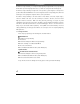
1-4-1 Top Panel The top panel of the Wireless Hotspot Gateway is shown below.
LEDs Indication LED State Description POWER Off The Wireless Hotspot Gateway is not receiving electrical power. Green The Wireless Hotspot Gateway is receiving electrical power. Off The Wireless Hotspot Gateway status is defective. Green The Wireless Hotspot Gateway status is complete. SYS Green (Blinking) During firmware upgrades, this system LED will blink. WAN Off Port has not established any network connection. Green A port has established a valid 10/100Mbps network connection.
1. RS-232: Reserve for manufacture use. 2. LAN (1-4): The rear panel supports four auto-sensing RJ-45 ports and all ports can be auto-switched to MDI-II connections. The LAN ports used for linking hosts or other network devices. The individual port can be either connected to 100BaseTX networks or 10BaseT networks. When connecting to a 100BaseTX network, the ports operate at 100Mbps in half-duplex mode or 200Mbps in full-duplex mode.
LED Indicators One POWER LED One WAN 10/100M Link/Activity LED Four LAN 10M/100M Link/Activity LEDs One Wireless Link/Activity LED One System LED Power Requirement External Power Adapter Input: 100-240 VAC, 50/60 Hz Output: 5V, 2A Environment Conditions Operating Temperature: 0 to 50°C Storage Temperature: -10 to 60°C Operating Humidity: 10~80% non-condensing Storage Humidity: 10% to 90% non-condensing Certifications FCC part 15 Class B, CE, CSA, VCCI Class B, CE / R&TTE, C-Tick Dimension Size: 242 (L) x 13
1-5-2 Software Specifications Networking • IEEE802.3 10BaseT Ethernet • IEEE802.3u 100BaseTX Fast Ethernet • IEEE802.3af Power over Ethernet • IEEE802.11b Wireless LAN • IEEE802.
Security and Firewall • Layer 2 Isolation Security • SSL User Login page/ Configuration Page • SSL Administration • VPN Pass through (IPSec/PPTP) • Customize SSL Certificate • Pass Through IP/MAC/URL Address • Restricted Destination Filtering IP/URL • VPN (IPSec/PPTP) Pass through • PPTP VPN Client • WEP • WPA Management • Web-based Management Tool • Firmware Upgrade via HTTP/TFTP • Wizard setup for step-by-step Configuration • Backup/Restore/Factory Default Setting • Remote A
2. Installation The followings are instructions for setting up the Wireless Hotspot Gateway. Refer to the illustration and follow the simple steps below to quickly install your Wireless Hotspot Gateway. 2-1 Wall-Mounting The Wireless Hotspot Gateway can be wall-mounted on a wall by applying the two mounting brackets on screws. Figure 2-1 Wall-Mounting Bracket - Bottom of Wireless Hotspot Gateway Please refer to the following instructions for mounting a Wireless Hotspot Gateway on a wall or other surface.
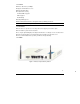
2. Mount the device in the rack, using three rack-mountings screws. Note: If the screws are not properly anchored, the strain of the cables connected to the Wireless Hotspot Gateway rear panel connectors could pull out the Wireless Hotspot Gateway from the wall. 2-2 Connecting the Antennas The Wireless Hotspot Gateway provides two antenna connectors on the rear of the unit.
ISP Requirements Verify whether your ISP use fixed or dynamic IP. If it is a fixed IP, be sure to get the IP from your ISP. For dynamic IP, which is mostly used, the PC will get the IP automatically whenever it hooks up on the modem.
2-4 Getting Start 1. Place the Wireless Hotspot Gateway and AG-200E Printer on a flat work surface. 2. Connect the Ethernet cable to the Wireless Hotspot Gateway’s LAN port. 3. Connect the other end of the Ethernet cable to the AG-200E Account Generator Printer’s RJ45 port. 4. Ensure that your modem and computer are both switched on. 5. Use the supplied cable to connect the Wireless Hotspot Gateway's WAN port to the modem. Check that the Cable/xDSL Status LED lights. 6.
2-2 POE (Power over Ethernet) Application Figure 2-6 POE Connection Note: To use the SMCWHSG14-G’s POE feature, follow the instructions for your specific POE device.
3. Configuring the Wireless Hotspot Gateway 3-1 Setting Wizard Step 1: Start your browser, and then enter the factory default IP address 192.168.2.1 in your browser’s location box. Press Enter. Figure 3-1 Web Browser Location Field (Factory Default) Step 2: The Wireless Hotspot Gateway configuration tools menu will appear. In the Username and Password field, type the factory default user name admin and password smcadmin and click Login.
Figure 3-4 System Quick View Click on reset button to clear the username and password data. Note: ) This Web agent is best viewed with IE 5.0 or Netscape 6.0 and above browsers. ) If you would like to change the password please see Step 10. ) Username and Password can consist of up to 20 alphanumeric characters and are case sensitive.
Step 3: Internet Connection Setting Select the appropriate Internet connection type to connect to your ISP. Figure 3-5 Internet Connection Setting Screen z DHCP Client The device can work as a DHCP client. This allows the device to obtain the IP address and other TCP/IP settings from your ISP. If your xDSL/Cable comes with this feature, please enable Use DHCP Client.
z Static IP Setting If Static IP Setting is selected, then this screen will appear. Enter the IP address information provided by your ISP. Figure 3-7 Internet Connection Setting Screen—Static IP Setting Item Default Description IP Address 0.0.0.0 Enter the IP address provided by your ISP. Subnet Mask 0.0.0.0 Enter the subnet mask for the IP address. Gateway IP 0.0.0.0 Enter the Gateway IP Address provided by your ISP.
z PPPoE (Point-to-Point Protocol over Ethernet) If “PPPoE” is selected, then this screen will appear. Enter the username, password and other major fields. Figure 3-8 Internet Connection Setting Screen—PPPoE Setting Item Default Username Empty Password Empty PPP MTU Setting 1492 TCP MSS Setting 1452 Service Name Empty Description Enter the user name provided by your ISP. The user name can consist of up to 80 alphanumeric characters and is case sensitive.
Item Default Description Connect on Demand and Max Idle Time Connect on Demand Enable You can configure your Wireless Hotspot Gateway to cut your connection with your ISP after a specified period of time (Max Idle Time). If you have been disconnected due to inactivity, Connect on Demand enables your Wireless Hotspot Gateway to automatically Max Idle Time 10 Minutes re-establish your connection as soon as you attempt to access the Internet again.
z PPTP Client (Point-to-Point Tunneling Protocol) If “PPTP” is selected, then this screen will appear. Fill out all the information provided by your ISP. Figure 3-9 Internet Connection Setting Screen—PPTP Client Setting Item My IP Address My Subnet Mask Default Empty Empty Description Enter the PPTP local IP address provided by your ISP. Enter the PPTP local Subnet Mask IP address for the IP address (My IP Address).
Item Gateway IP Address Default Empty PPTP Server IP Address Empty Description Enter the PPTP server Gateway IP address provided by your ISP. Enter the PPTP server IP address provided by your ISP. Enter the user name provided by your ISP. The user name Username Empty can consist of up to 80 alphanumeric characters and is case sensitive. Password Empty Enter the user password provided by your ISP. The password can consist of up to 80 alphanumeric characters and is case sensitive.
Step 4: Wireless Setting This page allows you to define ESSID, Channel ID and WEP/WPA encryption for wireless connection. Figure 3-10 Wireless Setting Screen Item ESSID Default Description Wireless The ESSID is the unique name that is shared among all points in a wireless network. It is case sensitive and must not exceed 32 characters. Channel 6 Enter the channel ID for wireless connection.
Step 5: E-mail Server Setting Wireless Hotspot Gateway allows an extra Email server parameter to forward the subscriber’s E-mail. Figure 3-11 E-mail Service Setting Screen Item Default Description Email Server Redirect No Disables or enables email server redirect function. To prevent some subscriber’s original Email server may protect by firewall or NAT network. Wireless Hotspot Gateway provides an extra Email server parameter to forward the subscriber’s Email.
Step 6: Authentication Service Setting Figure 3-12 Authentication Service Setting Screen Item Default Description Built-in Authentication/ No Yes― No Authentication No Authentication) Wireless Hotspot Gateway provides Built-in Authentication for service provider to build up an Internet service without any extra authentication software.
Step 7: Billing Profile Setting The function is used to setup a billing profile. A billing profile is a description of how you want to charge your customer. Figure 3-13 Billing Profile Setting Screen Item Default Description Service Time to Finish Options: Time to Finish or Accumulation. Time to Finish― The subscriber can access Internet only one time with one account.
Item Default Description Currency $ Enter the appropriate currency unit or currency symbol. Number of 2 Enter the billing decimal value. The field maximum value is 3. 01~03 The index number of billing profile. In Wizard setup, we provide only decimals places No 3 billing profile. Name 30 minutes/ It is the name of billing profile. The maximum allowed characters 1 hour/ length is 12. 2 hours Usage Time 30 minutes/ The duration of the billing period.
Button B Button A Button C Figure 3-15 Account Generator Printer Step 9: Accounting Setting z Three-buttons Printer Setting Figure 3-16 Accounting Setting Screen (Three Buttons Printer) 34 SMCWHSG14-G
No Name Charge Usage Time Figure 3-17 Billing Profile Setting Screen Item Button A~ C Default 01 Description Define each button’s billing profile. Select one billing profile by clicking in the list box. Printout Number of copies to print 1 The system allows you to print all your bills. This value is number of copies. This function allows you to produce custom bill based on your requirements.
z Web-based Account Generator Setting Figure 3-18 Web-based Account Generator Setting Screen Item Default Billing Profile (Button Define each button’s billing profile. Select one billing profile by Description A~C) clicking in the list box. Printout Number of copies to 1 print The system allows you to print all your bills. Select one number of copies by clicking in the list box. - This function allows you to produce custom bill based on your requirements.
Item Default Description Password account Enter the password for web-based account generator. The password can consist of up to 80 alphanumeric characters and is case sensitive. Confirm Empty Enter the password for confirmation. Click on button to preview and operate account generator panel. Button A Button B Button C Figure 3-19 Account Generator Panel Click on button to create a new account.
Figure 3-20 Example-Acccount Printout 38 SM MCWHSG14-G
Click “View Account List” to display current account information. Figure 3-21 Account List Click on refresh button to update the account list page. The field name button in this list show that this list can be sorted in ascending/descending order according to the corresponding field name. Select the check boxes and click ‘Delete’ to delete accounts. Delete all accounts in account list. Note: This page will refresh automatically every 5 minutes.
Customize Printout Text This function allows you to produce custom bill based on your requirements. Figure 3-22 Customize Printout Text Setting Screen Click the button to displays the account on the screen as it would appear when printed.
Figure 3-23 Example- PC-connected printer Printout (Time to Finish) Figure 3-24 Example- PC-connected printer Printout (Accumulation) SMCWHSG14-G 41
Figure 3-25 Example- Account Generator Printer Printout (Time to Finish) 42 Figure 3-26 Example- Account Generator Printer Printout (Accumulation) SMCWHSG14-G
Figure 3-27 Example-Post-paid Printout 43 SMCWHSG14-G
Step 10: System Setting Figure 3-28 System Se etting Screen Item Default Description Usern name admin Enter the user name. n The user name can conssist of up to 80 alphanumeric characters and d is case sensitivve. Passw word admin Enter the user password. p The password p can co onsist of up to 80 alphanumeric characters and a is case sensitive. Confirrm Empty System date and time e YYYY/MM/DD Enter the passw word of administrrator for confirma ation.
3-2 Advanced Setup The Advanced Setting enables you to configure advanced settings related to accessing the Internet, including, 1. System 2. WAN/LAN 3. Server 4. Authentication 5. RADIUS 6. Billing 7. Accounting 8. Credit Card 9. Keypad 10. Customization 11. Pass Through 12. Filtering 13. Share 14. Portal Page 15. Advertisement 16. Walled Garden 17. DDNS 18. LAN Devices 19. Syslog 20. Session Trace 21. Bandwidth 22. Secure Remote 23. SNMP 24. Wireless 25.
3-2-1 System Define the Wireless Hotspot Gateway System configuration.
Figure 3-31 System Setting Screen Item Default Description The system name can consist of up to 40 System/Host Name Empty Domain Name Empty Location Information Empty Enter your location information. System The system date of the Wireless Hotspot Gateway. The Date valid setting of year is from 2002 to 2035. alphanumeric characters. The Domain name can consist of up to 80 alphanumeric characters.
Item Default Description Enables or disables NTP (Network Time Protocol) Time Server. Network Time Protocol can be utilized to NTP Setting Disable synchronize the time on devices across a network. A NTP Time Server is utilized to obtain the correct time from a time source and adjust the local time. Enter the IP address/domain name of NTP server. The Server IP/Domain Name Empty Time Zone GMT-12:00 Select the appropriate time zone for your location.
Item Default Description Option: default or customize certificate, These are two ways to create a certificate, one is purchase a SSL Certificate Default certificate from a certificate authority (Ex. Verisign or Thawte), and another is creating a self-certificate (For example: Uses OpenSSL tool). Click Apply button to save the new settings. Click Apply button, then Restart dialog box will appear. Click Apply to restart the system.
Figure 3-34 Restart Dialog Box z Device IP (LAN IP) Setting Figure 3-35 Device IP (LAN IP) Setting Item Default Description IP Address 192.168.2.1 The internal LAN IP address of your Wireless Subscriber Server Subnet Mask 255.0.0.0 Gateway. Enter the subnet mask for the IP address. z WAN MAC Address Figure 3-36 WAN MAC Address Setting Item IP Address Description The default MAC address is set to the WAN physical interface on device.
DHCP Client The device can work as a DHCP client. This allows the device to obtain the IP address and other TCP/IP settings from your ISP. If your xDSL/Cable comes with this feature, please enable Use DHCP Client. Figure 3-38 DHCP Client Setting Screen Static IP Figure 3-39 Static IP Setting Screen Item IP Address Description Enter the IP address for the xDSL/Cable connection (provided by your ISP). Subnet Mask Gateway IP Gateway Enter the subnet mask for the IP address.
PPPoE Figure 3-40 PPPoE Setting Screen Item User Name Default Empty Description Enter your PPPoE account name. The user name can consist of up to 80 alphanumeric characters and is case sensitive. Password Empty Enter your PPPoE password. The password can consist of up to 80 alphanumeric characters and is case sensitive. PPP MTU Setting 1492 MTU (Maximum Transfer Unit) specifies maximum transmission unit size. TCP MSS Setting 1452 MSS (Maximum Segment Size) specifies maximum segment size.
Item Service Name Default Empty Description Enter the service name provided by your ISP. The service name can consist of up to 64 alphanumeric characters and is case sensitive. Connect on Demand and Max Idle Time Connect on Demand Enable You can configure your Wireless Hotspot Gateway to cut Max Idle Time your connection with your ISP after a specified period of time 10 Minutes (Max Idle Time).
z PPTP Figure 3-41 PPTP Setting Screen Item My IP Address Default Empty Description A PPTP local IP address for the xDSL/Cable connection (provided by your ISP). My Subnet Mask Empty Enter the PPTP local IP address for the xDSL/Cable connection. Gateway IP Address Empty A PPTP local default gateway for the xDSL/Cable PPTP Server IP Address Empty Enter the PPTP server IP address for the xDSL/Cable Username Empty connection (provided by your ISP). connection (provided by your ISP).
Item Password Default Empty Description Enter your PPTP password. The password can consist of up to 80 alphanumeric characters and is case sensitive. PPP MTU Setting 1460 MTU (Maximum Transfer Unit) specifies maximum transmission unit size. TCP MSS Setting 1400 MSS (Maximum Segment Size) specifies maximum segment size. Connection ID/Name Empty Enter the connection ID or connection name. The connection ID/Name can consist of up to 81 alphanumeric characters and is case sensitive.
3-2-3 Server Figure 3-42 Server Setting Screen Item Default Description Web Server Enter the HTTP port number. The HTTP port allowed HTTP Port 80 range is 80 or 8010 to 8060. For access the Wireless Hotspot Gateway system under NAT, please tab the “http://HTTP Port IP Address: Port Number”. Enter the HTTPS port number. The HTTPS port allowed HTTPS Port 443 range is 443 or 4430 to 4440. For access the Wireless Hotspot Gateway system, please tab the “https://HTTPS Port IP Address: Port Number”.
Item Default Description There are three types of DHCP Services. DHCP Server Enable DHCP Disable—Disable the DHCP server function. DHCP Relay—Enable DHCP Relay function. DHCP Server—Enable DHCP server function. DHCP Relay DHCP Server IP Address DHCP Server DHCP Pool Starting Address Pool Size Lease Time To route DHCP through an external server, the administrator needs to enable the DHCP relay and assign a valid DHCP server IP address. Empty Enter the IP address of DHCP server.
3-2-4 Authentication Figure 3-43 Authentication Setting Screen Item Authentication Type Default Description No Option: No Authentication, Built-in Authentication or User Authentication Agreement. No Authentication― Subscriber can direct access the Internet without enter username and password.
Item Authentication Type Default Description No Built-in Authentication― Authentication Wireless Hotspot Gateway provides “Built-in Authentication” for service provider to build up an Internet service without any extra authentication software. If “Built-in Authentication” is selected, service provider can generate the subscriber account inside Wireless Hotspot Gateway, and the system will authenticate the subscriber login according to the generated account.
Copy and paste the following HTML Code into your home page to produce user agreement login page. Figure 3-44 Preview Redirect Login Page Code Item Default Description SSL Login Page Disable Enables or disables SSL security of login page. User Idle Time Out 5 Minutes The user idle time out valid range is 1-1440. Click Apply button to save the new settings.
3-2-5 RADIUS Authentication Figure 3-45 Authentication Setting Screen 61 SMCWHSG14-G
Item Default RADIUS Authentication Disable Description Option: No Authentication or RADIUS Server. Disable (No Authentication) ― Subscriber can direct access the Internet without enter username and password. Enable (RADIUS Authentication) ― Wireless Hotspot Gateway provides “RADIUS Authentication” for service provider to build up an Internet service with RADIUS server. If RADIUS Authentication is enabled, all subscribers’ authentication will send to RADIUS Server by RADIUS protocol (RFC 2865, 2866).
Item Retry Frequency ~ Default Description 3 The field default value is 3 seconds. Accounting Service Enable Enables or disables the accounting service. Interim Update Time 5 Minutes Specify the interim update time. Authentication Method CHAP Enter the authentication method of RADIUS server. Enable Disable Enables or disables WISPr Smart Client roaming function.
3-2-6 Billing The function is used to setup a billing profile. A billing profile is a description of how you want to charge your customer. Figure 3-46 Billing Setting Screen Item Pre-Paid Default Enable Description The subscribers can access Internet with pre-defined usage time.
If you change billing mode (Pre-paidÆPost-paid or Post-paidÆPre-paid), the system will erase all account and disconnect all on-line users. Figure 3-47 Message Box Item Default Enable Credit Card Service Disable Description Enables or disables the credit card service. Before you enable credit card service, make sure that your credit service is configured to work and the currency is American dollars. You must be converting all prices on your billing page into American dollars (U.S. dollars).
Figure 3-48 Credit Service Setting Screen Figure 3-49 Error Dialog Box (Credit Card Service=Enable) Item Time to Finish Default Enable Description The subscriber can access Internet only one time with one account. Once subscriber login, the pre-defined usage time will start until run out even the subscriber stop to access the Internet before run out.
Item Default Description Accumulation Accumulation Disable The subscriber can access Internet many times with one account. The system can keep and accumulate every single usage time until the pre-defined usage time run out. Idle Time Out 5 Min(s) The idle time out valid range is 1-1440. If the idle time out is set as 5 minutes, it means if the account doesn’t send packet in 5 minutes, the account will logout automatically.
Item No. Default +1~+10 Description The index number of billing profile. In Advanced setup, we provide 10 billing profile. Active - Click on check box, active or inactive the billing profile. Name - It is the name of billing profile. The maximum allowed characters length is 12. Account Usage time - Charge - The duration of the billing period. When this period expires, user account will be discontinued. Enter the unit rate amount (i.e. 35.
Figure 3-52 Post-paid Procedure Diagram Click Apply button to save the new settings. Click Apply button, the success dialog box appears. Click on Back to return to Billing setting screen.
3-2-7 Accounting This function allow service provider to generate the subscriber accounts.
Figure 3-55 Item Default Description Expiration Un-used account will be 12 hours Enter the number of hours/minutes/days. The field maximum deleted after ~hours value is 30 hours/minutes/days. automatically Accumulation account 3 months Enter the number and select time unit from list box. The field will be deleted after maximum value is 30 month/ days/ hours. logged in ~ Printout Number of copies to print 1 The system allows you to print all your bills.
Figure 3-56 Account Process Diagram Can be replenished by subscriber=Enable z Three-Button Printer/ Web-based Account Generator Panel Figure 3-57 Three-Button Printer/ Web-based Account Generator Panel Setting Screen Item Button A~C Default - Description Define each button’s billing profile. Select one billing profile by clicking in the list box. Print to… Account Select a printer to print out your account.
Item Default Description Use ~ for Discount Button A, Select one button (A~C) by clicking in the list box to Price Plan based on Disable assign the base charge and select enable to active the “Button Presses” discount price plan. Click on button to preview and operate account generator panel.
Figure 3-60 PC-connected Printer Printout (Time to Finish) 74 SMCWHSG14-G
Figure 3-61 Web-based Account Generator Printout (Accumulation) 75 SMCWHSG14-G
Figure 3-62 PC-connected Printer Printout (Accumulation) Note: Before configuring the accounting, you have to setting the billing profile of Web-based account generator panel.
Example: If press 7 times z Discount Price Plan based on “Button Presses” is disabled. Figure 3-63 Example 1 Amount: 7 x $2.00= $14.
z Discount Price Plan based on “Button Presses” is enabled. z The Charge by level is disabled. Figure 3-65 Example 2 Amount: 7 x $ 1 = $ 7.
Below is an example of the account printout.
z Discount Price Plan based on “Button Presses” is enabled. z Charge by level is enabled. Figure 3-67 Example 3 Amount: 2 x $2.00 + 4 x$ 1.50+1x$1= $11.
Below is an example of the account printout.
z Discount Price Plan based on “Button Presses” Figure 3-69 Discount Price Plan Setting Screen Item Charge by levels Default Enable Description Enables or disables the charge by levels function. Level 1~10 This field displays the level number of charge rate. Conditions When>= The discount condition. Button Presses - Enter the times of pressing button. Unit Price - Enter the amount of charge level. Click Apply button to save the new settings.
Figure 3-70 Success Dialog Box 83 SMCWHSG14-G
3-2-8 Credit Card Wireless Hotspot Gateway provides three credit card services (Authorize.net, iValidate.net, Secure Pay and Paypal) that allow service provider to authorize, process, and manage credit transactions directly from Internet. Figure 3-71 Credit Card Setting Screen Item Default Description Authorize.net Version 3.1 This field displays the merchant version. Merchant ID Empty Enter your Merchant ID. This is a Merchant Identification Number that you’re received from your Merchant Provider.
Item Default Description Need Disable If your Merchant Provider need password to authorize, click Password Empty Enter your Merchant password. Merchant Transaction Empty the check box to enable this function. Key The Merchant Transaction Key can be obtained directly from “Authorize.net”. The Merchant Transaction Key is similar to a password and is used by the Payment Gateway to authenticate transactions. The maximum character of the Merchant Transaction Key is 50.
Item Secure Server Address Default Description https://www. Enter the secure server address. vious.net/m erchant/proc esscc.asp Secure Pay Merchant ID Empty Enter your Merchant ID. This is a Merchant Identification Number that you’re received from your Merchant Provider. The maximum character of the Merchant ID is 7. Secure Pay Address https://www. Enter the address of SecurePay Payment Gateway. securepay.c om.au/secur epay/payme nts/process 2.
Figure 3-72 Success Dialog Box 87 SMCWHSG14-G
Please follow steps below to pay using credit card. Step 1: Choose Credit Card service on the login page.
Step 2: Select Service and enter payment information. Currency: American Dollars Figure 3-74 Service & Payment Information Setting Screen (Authorize.net) Item Default Description Payment Information Credit card number Empty Enter your credit card number. Credit card expiration date Empty Enter the credit card expiration date. The allowed format is Enter Email Address Empty MMYY. Enter your email address.
Figure 3-75 Service & Payment Information Setting Screen (iValidate.net) Item Default Description Payment Information Credit card number Empty Enter your credit card number. Credit card expiration date Empty Enter the credit card expiration date. The allowed format is Enter Email Address Empty Enter your email address. The system will e-mail your MMYY. account information once your payment information has been successfully authorized. Billing Address ZIP code Empty Enter the ZIP code.
Step 3: After valid payment information has been provided, the subscriber will obtain one valid account to login or the Figure 3-78 screen will appear.
3-2-9 Keypad Figure 3-78 Keypad Setting Screen 92 SMCWHSG14-G
Item Use for Pre-Paid Billing Default Description The system provides ten user definable hot keys through the use of the + Key plus the 1 through 0 keys across the top of the keypad. Keypad Hot Key +1~+0 It is the combination hot key for keypad application. Billing Profile - Select the billing profile you want to assign to the combination hot key. Use for Post-Paid Billing Define the basic rate of accounts. Base on ~ Minutes Select the billing unit by clicking in the list box.
Step 2: Click the Keypad in Advanced Setup Menu, define the Billing plan of pre-paid, and click Apply. Figure 3-80 Keypad’s Hot Key Setting Screen Step 3: You can use keypad to create subscriber accounts now. Press keypad hot key and then press Enter. A new subscriber account is generated, and the account information should be printed.
Step 4: Subscriber can use this account to access Internet now. z Use for Post-Paid Billing Step 1: Click the Billing in the Advanced Setup menu, select enable Post-paid, click Apply. Figure 3-82 Billing Setting Screen Step 2: Click the Keypad in Advanced Setup Menu, Define the billing plan of post-paid, click Apply.
Step 3: You can use keypad to create subscriber accounts now. Press Enter, a new subscriber account is generated, and the account information should be printed. This account information is including serial number, username, password and account create time. Figure 3-84 Step 4: When subscriber wants to terminate the Internet service, press *, serial number and then press Enter, a bill should be printed.
Account Generator Printer PS/2 Keypad Enter the date (MonthDate) Figure 3-86 Keypad’s Hot Key List z Daily Account Report Printout Press ABCAA B: Billing Profile UN: Purchase Unit Figure 3-87 Daily Account 97 SMCWHSG14-G
eport Printout z Montthly Account Re Pre ess ABCBB B B: Billing Profile UN: Purchase Unit Figure 3-88 Monthlyy Account z Systtem Status Repo ort Printout P Press ABCC CC 98 Figure 3-8 89 System Statuss Report Printoutt SM MCWHSG14-G
z Netw work Report Prin ntout Press AB BCAB eport Printout Figure 3-90 Network Re 99 SMCWH HSG14-G
3-2-10 Customization z Login Page The Wireless Hotspot Gateway provides three different login page formats, including standard, redirect, advanced and frame format. Standard For some service providers, they may hope to have a customize subscriber’s login page to the users. This function helps them to realize the ideal. The page elements are including login page title, background color, subtitle etc.
Item Copyright Default Description Enable The copyright is allowed the administrator to input a paragraph in the subscriber login page for copyright information. The maximum character of the copyright is 80. Background Color FFFFFF The background text color can be specified color. For the specified text color format please views the color grid. The allowed format is Hexadecimal. Figure 3-92 Login Page Screen Before you add logo to the login page, please make sure the logo image file is defined.
Redirect This allow service provider to redirect the subscriber’s browser to a specified home page. Figure 3-94 Redirect Login Page Setting Screen Copy and paste the following HTML Code into your home page to produce redirect subscriber login page.
Advanced This function allow user to design login page of Wireless Hotspot Gateway. Figure 3-96 Advanced Login Page Setting Screen Item Default Description Welcome Slogan Welcome The maximum allowed characters length is 80. Page Background None The page background can be none or specified color. For the background color format please views the color grid. The allowed format is Hexadecimal.
Figure 3-97 Color Gird Frame If “Frame” is selected the subscriber login page will be separate into Top Frame and Bottom Frame. Bottom Frame is a default format for username and password input, Top Frame is allowed to be specified a URL to link. www.caesarpark.com Figure 3-98 Frame Login Page Setting Screen Item Default Top Frame URL Link Empty Description The input format can be http://www.yahoo.com. The maximum character of the URL Link is 200.
Figure 3-9 99 Example-Logiin Page Screen z Logo o This function allows servvice provider to upload u the custo omer’s logo imag ge file which can be shown on dard login page and account prin ntout of PC-connected printer. the stand Figure e 3-100 Logo Settting Screen Ittem File Path De efault Emp pty Description n Enter the file pathname e of the logo file in i the File Path fiield. f to system. Click Apply button to save the logo file t delete the logo o file.
Figure 3-101 Logo Setting Screen Figure 3-102 Login Page 106 SMCWHSG14-G
z Information Window This function allow service provider can decide whether they want an “Information Window” pop-up on subscriber PC when authenticate successful or not and specified text of information window. Subscriber can type “http://1.1.1.1/info” to open the information window again or enter “http://1.1.1.1/logout” to logout immediately if accumulation billing selected.
Figure 3-104 Example-Login Page Screen Figure 3-105 Information Window Billing Type=Time to Finish Can be replenished by subscriber=Disable Figure 3-106 Information Window Billing Type=Time to Finish 108 Can be replenished by subscriber=Enable SMCWHSG14-G
Figure 3-107 Information Window Billing Type=Accumulation Can be replenished by subscriber=Disable Figure 3-108 Information Window Billing Type=Accumulation Can be replenished by subscriber=Enable 109 SMCWHSG14-G
Figure 3-109 Information Window Super Subscriber Account (Default username=”super” & password=”super”) Figure 3-110 Logout Successfully Dialog Box Billing Type=Accumulation Figure 3-111 Alarm Dialog Box1 110 SMCWHSG14-G
z Account Printout This function allow service provider to specified text of account printout.
Click Apply button to save the new settings. Click Apply button, the success dialog box appears. Click on Back to return to Account Printout Customization setting screen.
Figure 3-115 Account Generator Printer Printout Figure 3-116 Account Generator Printer Printout 113 SMCWHSG14-G
z Credit Card Standard Login Page This function allow service provider to customize the additional credit card message for the standard login page.
Figure 3-119 Billing Setting Screen 115 SMCWHSG14-G
Service Selection Page This function allow service provider to customize the additional credit card message for the standard login page. Customer Information 116 Figure 3-120 Service Selection Page Setting Screen (Authorize.
Figure 3-121 Service Selection Page Setting Screen (iValidate.
Figure 3-122 Service Selection Page Setting Screen (Secure Pay) 118 SMCWHSG14-G
Figure 3-123 Service Selection Page (Authorize.
Figure 3-124 Service Selection Page (iValidate.
Figure 3-125 Service Selection Page (SecurePay) 121 SMCWHSG14-G
Successful Page Figure 3-126 Successful Page Setting Screen 122 SMCWHSG14-G
Figure 3-127 Example-Successful Page Fail Page This function allow service provider to customize the message for the fail page. Figure 3-128 Fail Page Setting Screen Click Apply button to save the new settings.
Figure 3-129 Fail Page Click Apply button, the success dialog box appears. Click on Back to return to Credit Card Customization setting screen.
z User Agreement Page This function allow user to design user agreement page of Internet Subscriber Server.
3-2-11 Pass Through This function allow administrator to set some special devices pass through the Wireless Hotspot Gateway system. Because some network devices might be constructed under the Wireless Hotspot Gateway. However these devices needn’t be checked and authorized. The Wireless Hotspot Gateway provides a pass through list and the administrator can control which devices can be pass through with authentication.
Item D Default Pass Through D Disable Description n Enables or disables the e pass through fu unction. Destiination URL/IP Address A Pass Through T URL o or Website E Empty Enter the URL Pag ge; please use this format such like www.yahoo.com””. The maximum m character of the e URL Page “http://w is 50. Start IP Address E Empty Enter th he start IP addre ess of you wants pass through. End IP Address E Empty Enter th he end IP addresss of you wants pass p through.
3-2-12 Filtering Filtering allows the system administrator to have a list of restricted destinations, which is useful to block specified Internet websites or Intranet areas. Figure 3-134 Filtering Setting Screen Item Default Description Filtering Disable Enables or disables filtering function. HTTP Message The Web Site Enter the http message. The maximum character of the HTTP to display when a is blocked by message is 200.
Item Defa ault Description n Restricct Destination URL orr Website Emp pty Enter the URL Page off you wants to filter; f please use e this format ke “http://www.ya ahoo.com”. The maximum chara acter of the such lik URL Pa age is 50. Start IP P Address Emp pty Enter th he start IP addre ess of you wants to filter. End IP P Address Emp pty Enter th he end IP addresss of you wants to t filter. IP Add dress Emp pty Enter th he destination IP P address of you wants to filter.
3-2-13 Share This feature allows sharing the network devices after subscriber successful login. Figure 3-136 Share Device Setting Screen Item Default Description Share LAN resource Disable Enables or disables share LAN resource function. Resource Name Empty Enter the device name. The maximum character of the resource name is 30. Resource IP Address Empty Enter the IP address of device in the format “xxx.xxx.xxx.xxx”. Resource MAC Address Empty Enter the MAC address of device.
Note: 1. You must use the “Search IP” method to search for a device on the network. Please follow steps below to search your device. ) Click Start, and then click Search. ) Click Computers or People. ) Click “A computer on the network”. ) In Computer, type the IP address of the device you want to find. Click Search. 2. The function support only Unicast and IP Protocol. Click Add to List button to add a new entry. Click Apply button to save the new settings.
3-2-15 Advertisement The system allow service provider to input 10 URL links for advertisement link purpose. Figure 3-139 Advertisement URL Link Setting Screen Item Default Frequency One Time Only Description One Time Only—One Time Only means to send the advertisement link once after the subscriber Login. Every~Min(s)—The field means to send the advertisement link every interval minutes. The value range is 1 to 60 (minutes).
Click Apply button, the success dialog box appears. Click on Back to return to Advertisement URL Link setting screen. Figure 3-140 Success Dialog Box 3-2-16 Walled Garden We prepare ten URL links that allows subscriber to access the specific Web pages even they didn’t have a username or password. It’s free trying and can use for advertisement. Yahoo www.yahoo.com MSN www.msn.com Microsoft www.microsoft.
Figure 3-141 Walled Garden 134 SMCWHSG14-G
Name Figure 3-142 Login Page Item Description Link 1~10 Name The name is allowed user to set the prompt string in user customize login page. The URL 1~10 The input format can be “http://www.yahoo.com”. The maximum character of the maximum allowed characters length is 80. Link# is 200. Click Apply button, the success dialog box appears. Click on Back to return to Walled Garden setting screen.
3-2-17 DDNS The DDNS service (Dynamic Domain Name Service), an IP Registry provides a public central database where information such as email addresses, host names, IP addresses etc. can be stored and retrieved. This solves the problems if your DNS server uses an IP associated with dynamic IP addresses. When the ISP assigns the Wireless Hotspot Gateway a new IP, the Wireless Hotspot Gateway must inform the DDNS server the change of this IP so that the server can update its IP-to-DNS entry.
Item Force to update every Default 1 day ~day(s) when WAN IP Description Enter a number in the field to set the force update interval (in days). address keeps no change No 01~03 The index number of a DDNS account. Active Disable Click on check box, active or inactive the DDNS record. Click the Update Status Now button to do manual update. Settings Enter the account information of DDNS Server. Status YY/MM/DD Display the update date, time and status.
Click Apply button, the success dialog box appears. Click on Back to return to DDNS setting screen. Figure 3-145 Success Dialog Box 3-2-18 LAN Devices Administrator can direct remote control to LAN Devices via the Wireless Hotspot Gateway implemented the feature. Figure 3-146 LAN Devices Setting Screen Item Polling Interval Default 5 Min. Description The default value is 5 minutes.
1440. Item Default Device Name Empty Description The LAN device name. The maximum character of the device name is 20. Virtual Port 0 The virtual port number valid range is 60001 to 60050 or 5900 to 5910. Device IP Address Empty Device Server Port 0 Enter the IP address of LAN device in the format “xxx.xxx.xxx.xxx” Enter the server port of LAN device. Device MAC Address Empty The MAC address of LAN device.
3-2-19 Syslog The function allows the device to transmit event messages to your syslog server or your email address for monitoring and troubleshooting. z Syslog Setting Figure 3-147 Syslog Setting Screen Item Syslog Default Disable Description Enables or disables the syslog server function. Syslog on LAN Server IP Address Empty Enter syslog server’s IP address. The Wireless Hotspot Gateway will send all of its logs to the specified syslog server.
Item Default Description Syslog on WAN Server 1 IP Address Empty Enter IP address of first syslog server. Server 2 IP Address Empty Enter IP address of second syslog server. Send to Email Disable Enables or disables the send to e-mail function. E-mail Server IP Address or Domain Empty Enter the SMTP server IP address or domain name. The Name maximum allowed characters length is 50. SMTP Port 25 The SMTP port allowed range is 25 or 2500 to 2599.
z Log Categories Figure 3-149 Log Settings Screen Item Interval Time Syslog Disable Email Disable Description Click on check box, send log information to your syslog server. Click on check box, send log information to your e-mail address.
Item Interval Time Description System Syslog Information 60 minutes The log included system information would be sent according to specified interval time.
Item Logged-in Users Interval Time 60 minutes Description A log included logged-in users information would be sent according to specified interval time. Format: (Id, Mac Address) (Logged-in Users, Type, Number of logged-in users, Start Number, End number) (Username, User IP, User MAC, Interface, Login time, RxData count, TxData count)(…)(…) Type: Dynamic | Super | User agreement | No Authentication If the type of Logged-in user is Super Subscriber, Username will be “********”.
Subscriber Trace Relationship Type Event Time Left TimeToFinish Finished 00:00:00 TimeToFinish Replenished 00:12:00 to S/Nxxxxxx TimeToFinish Deleted 00:12:00 Accumulation Finished 00:00:00 Accumulation Replenished 00:12:00 to S/Nxxxxxx Accumulation Logout 00:48:00 Accumulation Idle-Timeout 00:48:00 Accumulation Deleted 00:48:00 Accumulation Account Expired 00:48:00 PostPaid Logout ****** PostPaid Idle-Timeout ****** PostPaid Deleted ****** PostPaid Finished ****** P
Item Interval Time Description LAN Devices Management Category LAN Devices Information 60 minutes A log including current LAN Devices Status will be sent according to specified interval time. Format: (Id, MAC Address) (LAN Devices Information, Number of devices, Start Number, End number) (Device name, Status)(…)(…) LAN Devices Alarm When device A log will be sent if one of the LAN Devices detected results fail is "Fail".
3-2-20 Session Trace Session Trace is an intelligent function to help service provider to trace every user’s access behavior. When “session trace” is enable , the system will collect information such like destination IP, destination port, source IP, source MAC, source port by every user and send the collected information in text format file to specified TFTP server. Figure 3-151 Session Trace Setting Screen Item Default Description Session Trace Disable Disables or enables session trace function.
3-2-21 Bandwidth The function enables administrator to limit bandwidth usage on a per user basis (MAC address). That prevents users from consuming a disproportionately large amount of bandwidth so every user gets a fair share of the available bandwidth. Figure 3-152 Bandwidth Setting Screen Item Default Description Bandwidth Disable Enables or disables Bandwidth Management. Maximum Upstream 64Kbps Specify the amount of upstream bandwidth.
3-2-22 S Secure Remote This feature allows you to create a secu ure connection to o a remote site or o back end systtem with VPN Client. If “Secure e Remote” is ena abled, the RADIUS packet/ sysllog will be transsferred to this PPTP C secure cconnection. Figure 3-15 53 Secure Remotte Setting Screen n Item Auto--connect at Default Disable Start--up (Always Descriptio on Ena able the check box to automatically establish the PPTP conn nection.
3-2-23 SNMP The SNMP Agent Configuration screen enables you to access to your device via Simple Network Management Protocol. If you are not familiar with SNMP, please consult your Network Administrator or consult SNMP reference material. You must first enable SNMP on the SNMP Agent Configuration screen. Figure 3-154 SNMP Setting Screen Item SNMP Default Disable Description Disables or enables the SNMP management.
Item Privileges Default Read/Write Description Choose “Read”, “Write”, “Trap Recipients” and “All” for different privileges. The default setting of the entry 2 is “write” and others are “read”. Status Valid/Invalid Chosen “Valid” or “Invalid”. The default setting of entry 1, 2 are valid and others are invalid.
3-2-24 Wireless Figure 3-155 Wireless Setting Screen 152 SMCWHSG14-G
Item Default Description General Settings The ESSID is the unique name that is shared among all ESSID Wireless Channel 6 points in a wireless network. It is case sensitive and must not exceed 32 characters. Select the channel ID for wireless connection. Select disable to allow wireless station to communicate with Security Disable the device without any data encryption. Select enable to enable WPA or WEP data encryption.
Item Default Description This selects which of the Keys the Wireless Hotspot Gateway uses when it transmits. You can change the selected encryption key every now and then to increase the security of your network. Note: You have to configure all WEP keys (1~4), and select one of the four WEP key. WEP Key 1 Enter 5 characters (case sensitive) for ASCII 64-bit WEP Key. Enter 10 characters (case sensitive) for Hex 64-bit WEP Key. Enter 13 characters (case sensitive) for ASCII 128-bit WEP Key.
Item Default Description This setting determines the size at which packets are Fragmentation Threshold 2432 fragmented. Enter a setting ranging from 256 to 2432 bytes. Use a low setting in areas where communication is poor or where there is a great deal of radio interference. The preamble type is a section of data at the head of a packet that contains information the Wireless Hotspot Preamble Type Long Preamble Gateway and client devices need when sending and receiving packets.
Click Apply button, the restart dialog box appears. Click on Apply to restart the system. Figure 3-156 Restart Dialog Box This operation will load the default manufacturer configuration to the system. All this page (Wireless) configuration setup will be replaced by default settings.
Figure 3-158 Application 3-3 System Status Display Wireless Hotspot Gateway system basic status, including, 1. System 2. Account List 3. Account Log 4. Current User 5. DHCP Clients 6. Session List 7.
3-3-1 System The System Information Menu displays current system basic information including the service connection message, host name, LAN, WAN, DHCP Configuration, DNS, E-mail Redirection, SSL Certificate, network traffic Information and the system firmware version number.
Figure 3-161 System Status Screen 159 SMCWHSG14-G
3-3-2 Account List You can display a list of all the account information on this device. This table includes the username, password, usage time, time created, login time, expiration time and status. Figure 3-162 Account List Click on refresh button to update the account list page. Click the column button to sort the column in ascending/descending order. Select the check boxes and click ‘Delete’ to delete the accounts. Delete all accounts in account list.
3-3-3 Account Log The account log shows the accounts’ log information. Figure 3-163 Account Log This allow you to export the account logs to a text file format. (export.log) Click on Clear Log to remove all account log entries. Click on refresh button to update the account log page. Click the column button to sort the column in ascending/descending order.
3-3-4 Current User Display the current logged-in subscribers’ status. It allow service provider to disconnect any subscribers. Figure 3-164 Current User List Figure 3-165 Current User List (super account) Figure 3-166 Current User List (No Authentication) Click on refresh button to update the current user list page. Click the column button to sort the column in ascending/descending order. Select the check boxes and click ‘Disconnect’ to disconnect accounts.
3-3-5 DHCP Clients The DHCP client table shows the current DHCP users on the LAN. Figure 3-167 Current User Screen 3-3-6 Session List The remote site administrator could monitor the real time usage status of Wireless Hotspot Gateway via this page.
3-3-7 LAN Devices You can manage all devices by clicking on device name to access device’s Web-based interface. Figure 3-169 LAN Devices Status Screen Click Figure 3-170 Example- Ethernet Switch Management Screen 3-4 System Tools This allows service provider or administrator to process Firmware upgrade, change password and backup or restore configuration. 1. Configuration 2. Firmware 3. Boot Code 4. System Account 5. SSL Certificate 6. Ping Command 7. Restart 8.
3-4-1 Configuration Use the Configuration item to save, restore or reset configuration parameters of the Wireless Hotspot Gateway. Figure 3-172 Configuration Setting Screen Item Backup Default Description Click it to save the system configuration to your computer. (export.cfg) Remote TFTP Server IP Empty Enter the IP address of TFTP Server. Address File Name Empty Enter the file name in the File Name field. Restore Click it to restore your system configuration.
3-4-2 Firmware Upgrade The Firmware Upgrade menu loads updated firmware to be permanent in flash ROM. The download file should be a binary file from factory; otherwise the agent will not accept it. After downloading the new firmware, the agent will automatically restart it. z Manual Firmware Upgrade Figure 3-173 Manual Firmware Upgrade Setting Screen Item Default Description This allow administrator to upgrade the firmware via HTTP.
z Scheduled Firmware Upgrade Scheduled Firmware Upgrade is a program that enables an automatic upgrade to the latest firmware version through the TFTP server. Figure 3-174 Scheduled Firmware Upgrade Setting Screen Item Default Disable/Enable Disables or enables the scheduled firmware upgrade function. Description TFTP Server IP Empty Enter the IP address of TFTP Server. File Synchronization Empty Enter the file name and location in the File Synchronization field.
3-4-3 Boot Code Figure 3-176 Boot Code Upgrade Setting Screen 3-4-4 System Account Use the System Account screen to change the system accounts.
Item Description Username The username can consist of up to 20 alphanumeric characters and is sensitive. Password The password can consist of up to 20 alphanumeric characters and is sensitive. Confirm The password for confirmation. Super Subscriber Disables or enables the super account function. Idle Time Out The user idle time out valid is 1 to 1440 minutes. If the idle time out is set as 5 minutes, it means if the account doesn’t send packet in 5 minutes, the account will logout automatically.
Or Figure 3-180 System Quick View z Web-Based Accounting Manager Step 1: Start your Web browser and enter the factory default IP address192.168.2.1 in your browser’s location box. Press Enter.
Step 2: The Wireless Hotspot Gateway configuration main menu will appear. Enter account as the Username and account as the password and click Login Figure 3-182 Web-Based Accounting Manager Login Screen Username: account Password: account Step 3: After a valid user name and password have been provided, the account Generator Panel homepage will appear.
z Supervisor Account Step 1: Start your Web browser and enter the factory default IP address 192.168.2.1 in your browser’s location box. Press Enter. Figure 3-184 Web Browser Location Field (Factory Default) Step 2: The Wireless Hotspot Gateway configuration main menu will appear. Enter supervisor as the Username and supervisor as the password and click Login.
z Super Subscriber Account Start your Web Browser; a subscriber login page will appear. Enter super as the Username and super as the password and click Enter, you can use Internet now. Username: super Password: super Figure 3-187 Subscriber Login Page 3-4-5 SSL Certificate The function allows you to download the registered CA certificate into the Wireless Hotspot Gateway. Figure 3-188 SSL Certificate Download Setting Screen Note: The password field must the same as the CA’s registered password.
3-4-6 Pin Command The Ping function can check the Wireless Hotspot Gateway networking connective or not. Figure 3-189 Ping Command Screen Item IP or URL Description Enter the IP address or the URL link. 3-4-7 Restart If your Wireless Hotspot Gateway is not operating correctly, you can choose this option to display the restart Wireless Hotspot Gateway screen. Clicking the apply button restart the Wireless Hotspot Gateway, with all of your settings remaining intact.
Appendix A Signal Connection Arrangements RJ-45 Ethernet Port The Wireless Hotspot Gateway RJ-45 Ethernet port can connect to any networking devices that use a standard LAN interface, such as a Hub/Switch Hub or Router. Use unshielded twisted-pair (UTP) or shield twisted-pair (STP) cable to connect the networking device to the RJ-45 Ethernet port. Depending on the type of connection, 10Mbps or 100Mbps, use the following Ethernet cable, as prescribed. 10Mbps: Use EIA/TIA-568-100-Category 3, 4 or 5 cable.
Appendix B Regulations/EMI Compliance FCC Regulatory Statement Part 15-Class B compliant device This device complies with Part 15 of the FCC Rules. Operation is subject to the following conditions: 1. This device may not cause harmful interference, and 2. This device must accept any interference received, including that which may cause undesired operation. This equipment has been test and found to comply with the limits for a computing device, pursuant to Part 15 of the FCC Rules.
TECHNICAL SUPPORT From U.S.A. and Canada (24 hours a day, 7 days a week) Phn: 800-SMC-4-YOU / 949-679-8000 Fax: 949-502-3400 ENGLISH Technical Support information available at www.smc.com FRENCH Informations Support Technique sur www.smc.com DEUTSCH Technischer Support und weitere Information unter www.smc.com SPANISH En www.smc.com Ud. podrá encontrar la información relativa a servicios de soporte técnico DUTCH Technische ondersteuningsinformatie beschikbaar op www.smc.