` Comcast Wireless Cable Modem Gateway FastFind Links Getting to Know the Gateway SMCD3GNV User Manual Installing the Gateway Preconfiguration Guidelines Configuring the Gateway Configuring the Gateway’s mso Interface
SMC Networks 20 Mason Irvine, CA. 92618 U.S.A. Copyright © 2012 SMC Networks All Rights Reserved Information furnished by SMC Networks, Inc. (SMC) is believed to be accurate and reliable. However, no responsibility is assumed by SMC for its use, or for any infringements of patents or other rights of third parties which may result from its use. No license is granted by implication or otherwise under any patent or patent rights of SMC.
Contents Preface.................................................................................................................... vii Key Features .............................................................................................................viii Document Organization .............................................................................................. ix Document Conventions ..............................................................................................
Contents Confirming Your Computer’s Link Status .................................................................. 35 4 Configuring the Gateway ................................................................................... 36 Accessing the Gateway’s Web Management ............................................................ 37 Understanding the Web Management Interface Menus ............................................ 38 Web Management Interface Menus ................................................
Contents Web Management Interface Menus ........................................................................ 104 Configuring the Gateway Settings ..................................................................... 106 Viewing At-a-Glance Configuration Settings................................................ 107 Configuring Email Notifications .................................................................... 108 Configuring Connections ...............................................................
Contents Troubleshooting Physical Network Problems .................................................... 182 Troubleshooting Configuration Problems .......................................................... 183 Determining Your IP Address ...................................................................... 183 Troubleshooting Software-Interaction Problems ............................................... 187 Specific Troubleshooting Procedures ................................................................
Preface The SMCD3GNV Wireless Cable Modem Gateway is the ideal all-in-one wired and wireless solution for the home or business environment. SMC is proud to provide you with a powerful, yet simple communication device for connecting your local-area network (LAN) to the Internet. This user manual contains all the information you need to install and configure your new SMCD3GNV Wireless Cable Modem Gateway.
Preface Key Features The following list summarizes the Gateway’s key features. Integrated, CableLabs-compliant DOCSIS 1.1/ 2.0 /3.0 cable modem. Integrated cable modem port for Internet connection to cable modem service. Four 10/100/1000 Mbps Auto-Sensing LAN ports with Auto-MDI/MDIX. High-speed 300 Mbps IEEE 802.11n Wireless Access Point. Dynamic Host Configuration Protocol (DHCP) for dynamic IP configuration, and Domain Name System (DNS) for domain name mapping. One USB 2.0 port.
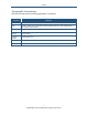
Preface Document Organization This document consists of four chapters and two appendixes. Chapter 1 - describes the contents in the Gateway package, system requirements, and an overview of the Gateway’s front, rear, top, and bottom panels. Chapter 2 - describes how to install the Gateway. Chapter 3 - describes how to configure TCP/IP settings on the computer you will use to configure the Gateway. Chapter 4 - describes how to configure the Gateway.
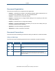
Preface Typographic Conventions This document also uses the following typographic conventions. Convention Description Bold Indicates text on a window, other than the window title, including menus, menu options, buttons, fields, and labels. Italic Indicates a variable, which is a placeholder for actual text provided by the user or system. Angled brackets (< >) are also used to indicate variables. screen/code Indicates text that is displayed on screen or entered by the user.
1 Getting to Know the Gateway Before you install your SMCD3GNV Wireless Cable Modem Gateway, check the package contents and become familiar with the Gateway’s front and back panels.
Getting to Know the Gateway Unpacking Package Contents Unpack the items in your SMCD3GNV Wireless Cables Modem Gateway contents and confirm that no items are missing or damaged. Your package should include: One SMCD3GNV Wireless Cable Modem Gateway One 2600 mAh battery One Category 5E Ethernet cable If any items are missing or damaged, please contact your cable service provider. Keep the carton, including the original packing material, in case you need to store the product or return it.
Getting to Know the Gateway Front Panel The front panel of your SMCD3GNV Wireless Cable Modem Gateway contains a set of lightemitting diode (LED) indicators. These LEDs show the status of the Gateway and simplify troubleshooting. Figure 1 shows the front panel of the SMCD3GNV Wireless Cable Modem Gateway. Table 1 describes the front panel LEDs. Figure 1.
Getting to Know the Gateway Table 1. Front Panel LEDs LED POWER Color White Description ON = power is supplied to the Gateway. OFF = power is not supplied to the Gateway. US/DS White Blinking = ranging is in progress. ON = ranging is complete on 1 channel only. OFF = scanning for DS channel. DS White Blinking = scanning for DS channel. ON = synchronized on 1 channel only. US and DS Online Both US and DS blinking together = operator is performing maintenance.
Getting to Know the Gateway Rear Panel The rear panel of your SMCD3GNV Wireless Cable Modem Gateway contains a reset button and the ports for attaching the supplied power adapter and making additional connections. Figure 2 shows the rear panel components and Table 2 describes their meanings. Figure 2. Rear View of the SMCD3GNV Wireless Cable Modem Gateway Table 2.
Getting to Know the Gateway Table 3. Gigabit Ethernet Connectors LED Indicators LED Description Green Indicate 10/100/1000Mbps in use Amber Indicate 10/100Mbps in use Top Panel The top panel of your SMCD3GNV Wireless Cable Modem Gateway has a WPS button for configuring wireless security automatically. Figure 3 shows the WPS button. Figure 3.
Getting to Know the Gateway Using the Reset Button Using the reset button on the rear panel (see Figure 2 on page 15), you can perform two types of reset operations with the Gateway: Software reset – this reset operation power-cycles the Gateway and retains its current configuration settings. Factory default reset – this operation remove all overrides made to the Gateway’s factory default configuration and returns the Gateway to its original factory default settings.
2 Installing the Gateway This chapter describes how to install your SMCD3GNV Wireless Cable Modem Gateway.
Installing the Gateway Finding a Suitable Location Your SMCD3GNV Wireless Cable Modem Gateway can be installed in any location with access to the cable network. All of the cables connect to the rear panel of the Gateway for better organization and utility. The LED indicators on the front panel are easily visible to provide you with information about network activity and status.
Installing the Gateway Installing a Battery To install a battery into the Gateway, use the following procedure. 1. Place the Gateway on its side on a table. 2. Remove battery compartment door on the bottom panel and set it aside (see Figure 4). Figure 4. Removing the Battery Compartment Door 3. Insert the battery into the battery compartment (see Figure 5). Figure 5. Installing the Battery 4. Close the battery compartment.
Installing the Gateway Connecting to the LAN Using an Ethernet LAN cable, you can connect the Gateway to a desktop computer, notebook, hub, or switch. The Gateway supports auto-MDI/MDIX, so you can use either a standard straight-through or crossover Ethernet cable. 1. Connect either end of an Ethernet cable to one of the four Ethernet ports on the rear panel of the Gateway (see Figure 6). Figure 6. Connecting to an Ethernet Port on the Gateway Rear Panel 2.
Installing the Gateway Connecting the WAN To connect the Gateway to a Wide Area Network (WAN) interface: 3. Connect a coaxial cable to the port labeled Cable on the rear panel of the Gateway from a cable port in your home or office (see Figure 2 on page 15). Use only manufactured coaxial patch cables with F-type connectors at both ends for all connections. 4. Hand-tighten the connectors to secure the connection. 5.
Installing the Gateway Powering on the Gateway After making your connections, use the following procedure to power on the Gateway: 1. Connect the supplied power cord to the power port on the rear panel of the Gateway (see Figure 2 on page 15). 2. Connect the other end of the power adapter to a working power outlet. The Gateway powers on automatically, the POWER LED on the front panel goes ON, and the other front panel LEDs show the Gateway’s status (see Table 1 on page 14).
3 Preconfiguration Guidelines After you install your SMCD3GNV Wireless Cable Modem Gateway, use the information in this chapter to configure the TCP/IP settings on the computer that will be used to configure the Gateway. This chapter also covers other preconfiguration guidelines you should review before configuring the Gateway.
Preconfiguration Guidelines Configuring Your Computer for TCP/IP Before you configure the Gateway using its Web management interface, configure TCP/IP settings on the computer that will be used to configure the Gateway. The TCP/IP procedure to use depends on the operating system installed on the computer.
Preconfiguration Guidelines 4. In the Local Area Connection Status dialog box, click the Properties button. The Local Area Connection Properties dialog box appears. 5. In the Local Area Connection Properties dialog box, verify that Internet Protocol (TCP/IP) is checked. Then select Internet Protocol (TCP/IP) and click the Properties button. 6. Click Obtain an IP address automatically to configure your computer for DHCP. 7.
Preconfiguration Guidelines 5. In the Local Area Connection Properties dialog box, verify that Internet Protocol (TCP/IP) is checked. Then select Internet Protocol (TCP/IP) and click the Properties button. The Internet Protocol (TCP/IP) Properties dialog box appears. 6. In the Internet Protocol (TCP/IP) Properties dialog box, click Obtain an IP address automatically to configure your computer for DHCP. Click the OK button to save this change and close the Internet Protocol (TCP/IP) Properties dialog box.
Preconfiguration Guidelines Figure 10. Local Area Connection Properties Window 6. In the Internet Protocol Version 4 Properties dialog box, click Obtain an IP address automatically to configure your computer for DHCP (see Figure 11). Figure 11.
Preconfiguration Guidelines 7. Click the OK button to save your changes and close the dialog box. 8. Click the OK button again to save your changes. Figure 12.
Preconfiguration Guidelines Configuring Microsoft Windows 7 Use the following procedure to configure a computer running Microsoft Windows 7. 1. In the Start menu search box, type: ncpa.cpl Figure 13. Typing ncpa.cpl in the Start Menu Box The Network Connections List appears. Figure 14. Example of Network Connections List 2. Right-click the Local Area Connection icon and click Properties. 3.
Preconfiguration Guidelines Figure 15. Local Area Network Connection Properties Dialog Box 4. In the properties dialog box, click Obtain an IP address automatically to configure your computer for DHCP (see Figure 16).
Preconfiguration Guidelines Figure 16. Properties Window 5. Click the OK button to save your changes and close the dialog box. 6. Click the OK button again to save your changes.
Preconfiguration Guidelines Configuring an Apple® Macintosh® Computer The following procedure describes how to configure TCP/IP on an Apple Macintosh running Mac OS 10.2. If your Apple Macintosh is running Mac OS 7.x or later, the steps you perform and the screens you see may differ slightly from the following. However, you should still be able to use this procedure as a guide to configuring your Apple Macintosh for TCP/IP. 1. Pull down the Apple Menu, click System Preferences, and select Network. 2.
Preconfiguration Guidelines Disabling Proxy Settings Disable proxy settings in your Web browser. Otherwise, you will not be able to view the Gateway’s Web-based configuration menus. Disabling Proxy Settings in Internet Explorer The following procedure describes how to disable proxy settings in Internet Explorer 5 and later. 1. Start Internet Explorer. 2. On your browser’s Tool menu, click Options. The Internet Options dialog box appears. 3. In the Internet Options dialog box, click the Connections tab. 4.
Preconfiguration Guidelines Disabling Proxy Settings in Safari The following procedure describes how to disable proxy settings in Safari. 1. Start Safari. 2. Click the Safari menu and select Preferences. 3. Click the Advanced tab. 4. In the Advanced tab, click the Change Settings button. 5. Choose your location from the Location list (this is generally Automatic). 6. Select your connection method. If using a wired connection, select Built-in Ethernet. For wireless, select Airport. 7. Click the Proxies tab.
4 Configuring the Gateway After configuring your computer for TCP/IP and following the preconfiguration guidelines in Chapter 3, use that computer’s Web browser to configure your SMCD3GNV Gateway. This chapter describes how to use your computer’s Web browser to configure the Gateway.
Accessing the Gateway’s Web Management After configuring your computer for TCP/IP and reviewing the guidelines on the previous page, configure the Gateway using its Web-based management interface. From your Web browser, log in to the interface to define system parameters, change password settings, view status windows to monitor network conditions, and control the Gateway and its ports. To display the SMCD3GNV Wireless Cable Modem Gateway’s Web-based management screens, use the following procedure. 1.
Configuring the Gateway Note: Your cable modem operator may customize the login password, so please check with your operator for the correct password to use. 4. Click the LOGIN button to access the Gateway’s Web interface. The At a Glance menu appears, showing connection status information about the Gateway. You can also display this menu any time by clicking At a Glance in the menu bar.
Configuring the Gateway Logout and Change Password Buttons Status icons Menu bar Main area Control Panel Figure 19. Main Areas on the Web Management Interface Some menus in the menu bar have submenus associated with them. If you click a menu that has submenus, the submenus appear below the menu. For example, if you click the Connection menu, the submenus in Figure 20 appear. Figure 20.
Configuring the Gateway Web Management Interface Menus Table 4 describes the menus in the Web management interface. Table 4. Web Management Interface Menus and Submenus Menus and Submenus Description See Page At a Glance Lets you view information about your home network, connected devices, and recent network updates.
Configuring the Gateway Table 4. Web Management Interface Menus and Submenus Menus and Submenus Description See Page Parental Control Displays submenus that let you configure the Gateway for: Parental Control > Managed Sites • Blocked sites, blocked keywords, and trusted computers. 68 Parental Control > Managed Services • Blocked services and trusted computers. 75 Parental Control > Managed Devices • Managed and blocked devices.
Configuring the Gateway Viewing Information About Your Network and Connected Devices The At a Glance menu appears when you log in to the Gateway’s Web interface. You can also display this menu by clicking Gateway in the menu bar. Figure 21 shows an example of the At a Glance menu and Table 5 describes the menu. Figure 21. Example of the At a Glance Menu Table 5. At a Glance Menu Option Description Home Network Shows the status of your home network’s Ethernet and Wi-Fi home status.
Configuring the Gateway Viewing Information About Your Network and Connections Using the Gateway menu, you can: View and edit settings for the local IP network, and view Wi-Fi and Comcast network status. See page 44. View Comcast network settings and initialization procedures, including cable modem, downstream, and upstream information. See page 46. Configure IPv4 or IPv6 settings for the Gateway. See page 47. View and edit basic and advanced wireless settings. See page 49.
Configuring the Gateway Viewing the Gateway’s Connection Status The Status menu lets you view and edit the settings for your local IP network. You can also use this menu to view the status of the Wi-Fi network and Comcast network. To display the Status menu, click Connection in the menu bar, and then click the Status submenu. Figure 22 shows an example of the Status menu and Table 6 describes the menu. Figure 22.
Configuring the Gateway Table 6. Status Menu Option Description Local IP Network Displays information about the local network. The EDIT button opens the Local IP Configuration menu for viewing and changing IPv4 or IPv6 settings (see “Viewing and Editing Your Local IP Configuration” on page 47). WiFi Network Lets you view information about your Wi-Fi network.
Configuring the Gateway Viewing Comcast Network Information The Comcast Network menu lets you view settings for the Comcast network. This menu also shows information about the Gateway’s initialization procedures, cable modem settings, and downstream and upstream information. The information shown on this menu automatically updates (refreshes) every 10 seconds. To display the Comcast Network menu, click Gateway in the menu bar, and then click the Connection and Comcast Network submenus.
Configuring the Gateway Viewing and Editing Your Local IP Configuration The Local IP Configuration menu lets you view and change the Internet Protocol (IP) settings used by the Gateway. Fields are provided for configuring IP version 4 (IPv4) and the newer IP version 6 (IPv6). To display the Local IP Configuration menu, click Connection in the menu bar, and then click the Local IP Network submenu. Figure 24 shows an example of the Local IP Configuration menu and Table 7 describes the menu. Figure 24.
Configuring the Gateway Table 7. Local IP Configuration Menu Option Description IPv4 (for computers that use IPv4 Messaging) Gateway Address IPv4 IP address that the Gateway is to use. Subnet Mask IPv4 subnet mask that the Gateway is to use. DHCP Beginning Address Starting IP address range for the pool of allocated for DHCP IP addresses. The first two fields match the first two octets in the Gateway’s IP address and cannot be changed.
Configuring the Gateway Viewing and Editing Wireless Configuration The Wireless menu lets you view and change the Gateway’s basic and advanced wireless settings. To display the Wireless menu, click Gateway in the menu bar, and then click the Connection and WiFi submenus. Figure 25 shows an example of the Local IP Configuration menu and Table 8 describes the menu. Figure 25.
Configuring the Gateway Table 8. Wireless Menu Option Description Private Wireless Network Name MAC Address Security Mode Shows the name MAC address, and security setting, if any, for each private wireless network detected. An EDIT button is provided to change these settings. Private Wireless Basic Setting Mode Choices are: • 802.11 b/g = use this setting if you have a combination of IEEE 802.11b and IEEE 802.11g devices on your network. • 802.11n = use this setting if you have only IEEE 802.
Configuring the Gateway Option Description Channel Bandwidth Select a channel bandwidth of 20 or 20/40. • 20 = allows only single-channel operation (e.g., 20 MHz). • 20/40 = allows both single channel operation (20 MHz) and the wider bandwidth operation (40 MHz) by using two or more adjacent (contiguous channels). A 20/40 BSS is a wireless network that allows a wider bandwidth operation mode.
Configuring the Gateway Option Description Connect to Your WPS-supported Device Push Button Click this option to use the WPS button on the top panel of the Gateway to configure WPS (see Figure 3). PIN Number Click this option if you need to enter a PIN to configure WPS. Enter Wireless Client’s PIN If you clicked PIN Number, enter the PIN in this field. Pair with my WiFI Client Click this button to pair (connect) the Gateway’s Wi-Fi settings with your Wi-Fi client.
Configuring the Gateway Configuring Firewall Settings The Firewall menu lets you view and edit the settings for the Gateway’s internal firewall. The setting you select here is displayed at the top-right area of the Gateway’s Web interface. To display the Firewall menu, click Gateway in the menu bar, and then click the Firewall submenu. Figure 26 shows an example of the Firewall menu and Table 9 describes the menu. Figure 26. Example of the Firewall Menu Table 9.
Configuring the Gateway Figure 27. Custom Firewall Security Settings Table 10. Custom Security Settings Option Description Block http Blocks Hypertext Transfer Protocol (HTTP) downloads on ports 80 and 443. Block ICMP Blocks Internet Control Message Protocol (ICMP) traffic at the outer perimeter of the Gateway to protect against attacks such as cascading ping floods. Block Multicast Blocks unsolicited multicast packets.
Configuring the Gateway Viewing System Software Settings The Software menu is a read-only screen that shows the software version and packet cable version associated with the Gateway. To display the Software menu, click Gateway in the menu bar, and then click the Software submenu. Figure 28 shows an example of the Software menu. Figure 28.
Configuring the Gateway Configuring System Hardware Using the Hardware menu, you can: View system hardware information. See page 56. View information about the Gateway’s internal battery. See page 57. View the link status and Media Access Control (MAC) address for all four Gateway Ethernet ports. See page 58. View the status and MAC address of the Gateway’s Wi-Fi port. See page 59.
Configuring the Gateway Viewing Battery Settings The Battery menu is a read-only screen that shows information about the Gateway’s internal battery. To display the Battery menu, click Gateway in the menu bar, and then click the Hardware and Battery submenus. Figure 30 shows an example of the Battery menu. Figure 30.
Configuring the Gateway Viewing LAN Ethernet Settings The LAN Ethernet menu is a read-only screen that shows the link status and MAC address of the Gateway’s four Ethernet ports. To display the LAN Ethernet menu, click Gateway in the menu bar, and then click the Hardware and LAN submenus. Figure 31 shows an example of the LAN Ethernet menu. Figure 31.
Configuring the Gateway Viewing Wi-Fi Settings The WiFi menu is a read-only screen that shows the Wi-Fi link status and MAC address of the Gateway’s WiFi port. To display the WiFi menu, click Gateway in the menu bar, and then click the Hardware and WiFi submenus. Figure 32 shows an example of the WiFi menu. Figure 32.
Configuring the Gateway Configuring Your Home Network The Home Network Wizard menu is part of a 2-page wizard you can use to configure your home network. To display the first page of the Home Network Wizard, click Gateway in the menu bar, and then click the Wizard submenu. Figure 33 shows an example of the first page of the Home Network Wizard and Table 11 describes the page. Figure 33.
Configuring the Gateway Table 11. Home Network Wizard – Step 1 Option Description Gateway Name The name you want to assign to the Gateway. Assign a name so that this device will not be confused with other devices on your wireless network. We recommend you use a name that is meaningful to you so you can identify the Gateway easily. The Gateway name is case sensitive and can contain from 8 to 20 alphanumeric characters, but no spaces. Current Password Enter the current case-sensitive password.
Configuring the Gateway Figure 34.
Configuring the Gateway Table 12. Home Network Wizard – Step 2 Option Description Enter WiFI Network Name Enter the name of your wireless network (typically, the SSID). The Wi-Fi name will make it more obvious for others to know which network they are connecting to. Encryption Method The default selection of OPEN means your wireless transmissions are not protected.
Configuring the Gateway Working with Connected Devices Using the Computers menu, you can: View the computers that the Gateway has discovered using DHCP or Home Network Administration Protocol (HNAP). Manually add computers with static IP addresses to the wireless network. Edit computers with static IP addresses Disconnect online and offline computers from the wireless network. To display the Computers menu, click Connected Devices in the menu bar.
Configuring the Gateway Manually Adding Computers with Static IP Addresses to the Wireless Network To manually add a computer with a static IP address to your wireless network: 5. Under Online Computers, click the ADD COMPUTER WITH STATIC IP button. The Add Computer menu appears (see Figure 36). 6. Complete the fields in the Add Computer menu (see Table 13). 7. Click SAVE to save your settings (or click CANCEL to discard them).
Configuring the Gateway Table 13. Add Computer Menu Option Description Host Name Host name of the computer you want to add. Connection Read-only field that displays shows the network connection of Ethernet. MAC Address MAC address of the computer you want to add. Add a colon between each 2-character ID in the MAC address. For information about obtaining the MAC address of a computer, see “Determining a Computer’s MAC Address” on page 196.
Configuring the Gateway Table 14. Edit Computer Menu Option Description Host Name Read-only field that shows the host name of the computer you selected. Connection Read-only field that displays shows the network connection of Ethernet. Configuration Select whether the selected computer should be discovered by the Gateway using DHCP or a static IP address. If you select Static IP, enter the static IP address in the Static IP Address field. MAC Address Edit the MAC address of the selected computer.
Configuring the Gateway Configuring Parental Controls Regulating Web browsing can prevent children and workers from accessing dangerous content on the Internet, or having to make judgment calls over suitable relationships in chatrooms. The fact is, Web sites, chat-room users, and downloaded programs may not have the best interests of you, your family, or your workers at heart.
Configuring the Gateway Figure 38. Example of Managed Sites Menu Blocking Sites To block sites: 11. If the Managed Sites menu is not displayed, click Parental Control in the menu bar. 12. Next to Enabled Managed Sites, click Enabled. 13. Under Blocked Sites, click ADD. The Add Blocked Domain menu appears (see Figure 39). 14. Complete the fields in the Add Blocked Domain menu (see Table 15). 15. Click SAVE (or click CANCEL to discard your settings).
Configuring the Gateway Figure 39.
Configuring the Gateway Table 15. Add Blocked Domain Menu Option Description URL Enter the URL you want blocked. Always Block? Select whether you want the Gateway to always block this URL. Choices are • No = the Gateway does not always block this URL. Use the Set Block Time and Set Blocked Days to instruct the Gateway when to block this URL. • Yes = the Gateway always blocks this URL until you remove the block.
Configuring the Gateway Blocking Keywords To block keywords: 19. If the Managed Sites menu is not displayed, click Parental Control in the menu bar. 20. Next to Enabled Managed Sites, click Enabled. 21. Under Blocked Keywords, click ADD. The Add Blocked Keyword menu appears (see Figure 40). 22. Complete the fields in the Add Blocked Keyword menu (see Table 16). 23. Click SAVE (or click CANCEL to discard your settings).
Configuring the Gateway Figure 40.
Configuring the Gateway Table 16. Add Blocked Keyword Menu Option Description Keyword Enter the keyword you want blocked. Always Block? Select whether you want the Gateway to always block this keyword. Choices are • No = the Gateway does not always block this keyword. Use the Set Block Time and Set Blocked Days to instruct the Gateway when to block this Keyword. • Yes = the Gateway always blocks this keyword until you remove the block.
Configuring the Gateway Blocking Services Using the Managed Services menu, you can block access to certain services from local computers. This feature can be used to protect children from accessing inappropriate services. To display the Managed Services menu, click Parental Control in the menu bar, and then click the Managed Services submenu. Figure 41 shows an example of the menu. Figure 41. Example of Managed Services Menu To block services: 27.
Configuring the Gateway 33. To edit a blocked service, click the EDIT button next to the blocked service you want to modify, edit the settings on the Add Blocked Service menu (see Table 17), and click SAVE. 34. To delete a blocked service, click the X next to the service. When the Delete Service Block Rule message appears, click OK to delete the blocked URL or CANCEL to retain it. If you clicked OK, the service is removed from the Blocked Services area on the Managed Services menu. Figure 42.
Configuring the Gateway Table 17. Add Blocked Service Menu Option Description User Defined Service Enter the service you want blocked. Protocol The type of protocol associated with the service to be blocked. Choices are: • TCP (default) • UDP • TCP/UDP Start Port Starting port number on which the block will be applied. If necessary, contact the application vendor for this information. End Port Ending port number on which the block will be applied.
Configuring the Gateway Managing Devices and Access Types Using the Managed Devices menu, you can enable or disable managed devices and allow or block all access types. You can also add devices you want to block. To display the Managed Devices menu, click Parental Control in the menu bar, and then click the Managed Devices submenu. Figure 43 shows an example of the menu. Figure 43. Example of Managed Devices Menu Enabling or Disabling Managed Devices By default, all managed devices are disabled.
Configuring the Gateway Adding Blocked Devices To add devices you want to block: 35. If the Managed Devices menu is not displayed, click Parental Control in the menu bar, and then click the Managed Devices submenu. 36. Next to Blocked Devices, click ADD BLOCKED DEVICE. The Add Blocked Device menu appears (see Figure 44). 37. Completed the fields in the Add Block Device menu (see Table 18). 38. Click SAVE (or click CANCEL to discard your settings).
Configuring the Gateway Figure 44.
Configuring the Gateway Table 18. Add Blocked Device Menu Option Description Auto-Learned Devices To select a device that the Gateway automatically learned, select the device under AutoLearned Devices. Custom Device To select a custom device, enter the name and MAC address of the device in the Computer Name and MAC Address fields below Custom Device. Always Block? Select whether you want the Gateway to always block this device. Choices are • No = the Gateway does not always block this device.
Configuring the Gateway Generating Reports The Gateway provides a reporting feature for generating reports containing selected log messages. Using the Reports menu, you can define filters for reports and print or download reports. To display the Reports menu, click Parental Control in the menu bar, and then click the Reports submenu. Figure 45 shows an example of the menu. Note: You can use the Logs menu to apply log filters to reports. For more information. See page 94. Figure 45.
Configuring the Gateway Defining Report Filters The Report Filters area on the Reports menu lets you select the type of Reports you want to generate and the timeframe that the report is to cover. To define a report filter: 1. If the Reports menu is not displayed, click Parental Control in the menu bar, and then click the Reports submenu. 2. Perform the following steps under Report Filters: a.
Configuring the Gateway Using Advanced Features Using the Advanced Features menu, you can: Enable or disable port forwarding. See page 84. Enable or disable port triggering. See page 87. Enable or disable port blocking. See page 91. Use the Gateway’s UPnP feature to auto-discover devices. See page 92. Enabling or Disabling Port Forwarding Using the Firewall menu (described on page 53), you can configure the Gateway to create a firewall between your internal network and the Internet.
Configuring the Gateway Figure 46. Example of Port Forwarding Menu Adding a Port Forwarding Rule To add a port forwarding rule: 1. If the Port Forwarding menu is not displayed, click Advanced in the menu bar, and then click the Port Forwarding submenu. 2. Confirm that Enabled is selected (green) next to Enable Port Forwarding. If it isn’t click Enabled. 3. Click the ADD PORT FORWARD button. The Add Service menu appears (see Figure 47). 4. Complete the fields in the Add Service menu (see Table 19). 5.
Configuring the Gateway Figure 47. Add Service Menu Table 19. Add Service Menu Option Description Service Name Name for identifying the service. The name is for reference purposes only. Service Type The protocol you want to use with the service. Choices are: • TCP • UDP • TCP/UDP (default) Service IP Address IP address of the LAN computer or server that is running the service. Start Public Port Starting number of the port on which the service is provided.
Configuring the Gateway Disabling Port Forwarding To disable port forwarding: 1. If the Port Forwarding menu is not displayed, click Advanced in the menu bar, and then click the Port Forwarding submenu. 2. Next to Enable Port Forwarding, click Disabled. The ADD PORT FORWARD button becomes unavailable and all port forwarding rules that have been defined turn gray to show they are disabled. Enabling Port Forwarding To enable port forwarding: 1.
Configuring the Gateway Figure 48. Example of Port Triggering Menu Adding a Port Triggering Rule To add a port triggering rule: 1. If the Port Triggering menu is not displayed, click Advanced in the menu bar, and then click the Port Triggering submenu. 2. Next to Enable Port Triggering, click Enabled. 3. Click the ADD PORT FORWARD button. The Port Triggering Add menu appears (see Figure 49). 4. Complete the fields in the Port Triggering Add menu (see Table 20). 5.
Configuring the Gateway Figure 49. Port Triggering Add Menu Table 20. Port Triggering Add Menu Option Description Service Name Name for identifying the trigger. The name is for reference purposes only. Service Type The type of protocol you want to use with the trigger. Choices are: • TCP • UDP • TCP/UDP (default) For example, to track the H.323 protocol, the protocol type should be TCP. Trigger Port From From port ranges of the special application. For example, to track H.
Configuring the Gateway Disabling Port Triggering To disable port triggering: 1. If the Port Triggering menu is not displayed, click Advanced in the menu bar, and then click the Port Triggering submenu. 2. Next to Enable Port Triggering, click Disabled. The ADD PORT TRIGGER button becomes unavailable and all port triggering rules that have been defined turn gray to show they are disabled. Enabling Port Triggering To enable port triggering: 1.
Configuring the Gateway Enabling or Disabling Port Blocking By default, all four Ethernet ports on the Gateway are enabled and configured to autonegotiate the highest speed and duplex settings. If these settings prevent the Gateway from connecting with other devices, you can use the Port Blocking menu to configure the Gateway’s Ethernet ports to use specific speed and duplex settings. The Port Blocking menu also let you disable the Ethernet ports.
Configuring the Gateway Note: If you disable the port through which you are accessing the Gateway’s Web interface, you are disconnected and your session ends. You can reconnect to the Gateway using one of the other enabled LAN ports. Discovering Devices Using the Device Discovery menu, the Gateway can obtain protocol addresses of neighboring devices and discover the platform of those devices.
Configuring the Gateway Table 21. Device Discovery Menu Option Enable UPnP Description Determines whether the Gateway uses its UPnP feature to communicate with other devices or your operating system. • Enabled = allows the Gateway to use its UPnP feature to communicate with other devices or your operating system. (default) • Disabled = prevents the Gateway from using its UPnP feature to communicate with other devices or your operating system.
Configuring the Gateway Troubleshooting the Gateway Using the Troubleshooting menu, you can: Define log filters. See page 94. Test connectivity to a destination or IP address. See page 96. Reset the Gateway, reset your Wi-Fi router, or restore the Gateway to its factory default settings. See page 98. Change the password used to log in to the Gateway’s Web interface. See page 99. Note: For additional troubleshooting procedures, see Chapter 6.
Configuring the Gateway Defining Log Filters The Log Filters area on the Logs menu lets you select the type of logs you want to generate and the timeframe that the log is to cover. To define a log filter: 1. If the Logs menu is not displayed, click Troubleshooting in the menu bar, and then click the Logs submenu. 2. Perform the following steps under Log Filters: a.
Configuring the Gateway Testing Connectivity to Destination and IP Addresses There may be times when you encounter a problem trying to reach a certain destination. If you examine the Gateway’s configuration and operation and everything looks fine, the problem might be with a router up the line from the Gateway or with the line itself. To help you identify such issues, the Network Diagnostic Tools menu lets you test connectivity to a destination or IP address.
Configuring the Gateway Testing Connectivity to a Destination Address To test the Gateway’s connectivity to a destination address: 1. If the Network Diagnostic Tools menu is not displayed, click Troubleshooting in the menu bar, and then click the Diagnostic Tools submenu. 2. Under Test Connectivity Results, enter a destination address in the Destination Address field. Note: This procedure assumes that the destination address you enter is valid and operational. 3. Click the TEST CONNECTIVITY button.
Configuring the Gateway Restoring or Rebooting the Gateway The Restore / Reboot Gateway menu provides buttons for performing the following activities: RESET - restarts the Gateway while keeping any overrides you made to the Gateway’s factory default settings. RESET WI-FI Router - resets the Wi-Fi router without affecting the Gateway. RESTORE FACTORY SETTINGS - returns the Gateway to its factory default settings. Any overrides you made to the default settings will be removed.
Configuring the Gateway Changing the Login Password The Change Password menu lets you change the password used to log in to the Gateway’s Web interface. For security, we recommend you change the default log in password the first time you log in to the Web management interface to protect the Gateway from being tampered with. To display the Change Password, click Troubleshooting in the menu bar, and then click the Change Password submenu in the menu bar.
5 Configuring the Gateway’s mso Interface After configuring your computer for TCP/IP and following the preconfiguration guidelines in Chapter 3, use that computer’s Web browser to configure your SMCD3GNV Gateway using the Gateway’s mso interface. This chapter describes how to use your computer’s Web browser to configure the Gateway.
Accessing the Gateway’s Web Management After configuring your computer for TCP/IP and reviewing the guidelines on the previous page, configure the Gateway using its Web-based management interface. From your Web browser, log in to the interface to define system parameters, change password settings, view status windows to monitor network conditions, and control the Gateway and its ports. To display the SMCD3GNV Wireless Cable Modem Gateway’s Web-based management screens, use the following procedure. 1.
Configuring the Gateway’s mso Interface Note: Your cable modem operator may customize the login password, so please check with your operator for the correct password to use. 4. Click the LOGIN button to access the Gateway’s Web interface. The At a Glance menu appears, showing connection status information about the Gateway. You can also display this menu any time by clicking At a Glance in the menu bar.
Configuring the Gateway’s mso Interface Username Logout and Change Password Buttons Status icons Menu bar Main area Control Panel Figure 57. Main Areas on the Web Management Interface Some menus in the menu bar have submenus associated with them. If you click a menu that has submenus, the submenus appear below the menu. For example, if you click the Connection menu, the submenus in Figure 58 appear. Figure 58.
Configuring the Gateway’s mso Interface Web Management Interface Menus Table 4 describes the menus in the Web management interface. In Table 4 and the sections in this chapter, angle brackets show the path of menus and submenus. For example, Gateway > Connection > XFINITY Network means you click the Gateway menu in the menu bar, and then click the Connection and XFINITY Network submenus below Gateway.
Configuring the Gateway’s mso Interface Table 23. Web Management Interface Menus and Submenus Menus and Submenus Description See Page Parental Control > Managed Sites Restrict access to Web sites for non-trusted computers on the network.
Configuring the Gateway’s mso Interface Configuring the Gateway Settings Using the submenus below Gateway, you can: View at-a-glance settings for your network and connected devices. See page 107. Set up email notifications. See page 108.
Configuring the Gateway’s mso Interface Viewing At-a-Glance Configuration Settings The At a Glance menu appears when you log in to the Gateway’s Web interface. You can also display this menu by clicking Gateway > At a Glance in the menu bar. Figure 59 shows an example of the At a Glance menu and Table 24 describes the menu. Figure 59. Example of the At a Glance Menu<> Table 24.
Configuring the Gateway’s mso Interface Configuring Email Notifications Using the Email Notification menu, you can configure the Gateway to send email notifications when there is: A firewall and/or parental control breach An alert or warning > If desired, you can configure the Gateway to send the logs with the email. To display this menu, click Gateway > Email Notification in the menu bar. Figure 60 shows an example of the Email Notification menu and Table 25 describes the menu. Figure 60.
Configuring the Gateway’s mso Interface Table 25. Email Notification Menu Option Description Recipient Email Email address of the recipient who will receive email notifications.<> Notification Types Firewall Breach Determines whether an email notification is sent when the Gateway detects a firewall breach. • Yes = Gateway sends a notification when it detects a firewall breach. • No = Gateway does not send a notification when it detects a firewall breach.
Configuring the Gateway’s mso Interface Configuring Connections Using the submenus below Connections, you can: View and edit the settings for your local IP network, and view the Gateway’s Wi-Fi and XFINITY network connections. See page 111. Configure the Gateway’s IPv4 or IPv6 settings. See page 112. View and edit basic and advanced wireless settings. See page 114. View XFINITY network information. See page 121.
Configuring the Gateway’s mso Interface Viewing the Gateway’s Connection Status The Status menu lets you view and edit the settings for your local IP network. You can also use this menu to view the status of the Wi-Fi network and XFINITY network. To display the Status menu, click Gateway > Connection > Status in the menu bar. Figure 61 shows an example of the Status menu and Table 26 describes the menu. Figure 61.
Configuring the Gateway’s mso Interface Table 26. Status Menu Option Description Local IP Network Displays information about the local network. The EDIT button opens the Local IP Configuration menu for viewing and changing IPv4 or IPv6 settings (see “Viewing and Editing Your Local IP Configuration” on page 112). WiFi Network Lets you view information about your Wi-Fi network.
Configuring the Gateway’s mso Interface Table 27. Local IP Configuration Menu Option Description IPv4 (for computers that use IPv4 Messaging) Gateway Address IPv4 IP address that the Gateway is to use. Subnet Mask IPv4 subnet mask that the Gateway is to use. DHCP Beginning Address Starting IP address range for the pool of allocated for DHCP IP addresses. The first two fields match the first two octets in the Gateway’s IP address and cannot be changed.
Configuring the Gateway’s mso Interface Viewing and Editing Wireless Configuration The Wireless menu lets you view and change the Gateway’s basic and advanced wireless settings. To display the Wireless menu, click Gateway > Connection > WiFi in the menu bar .
Configuring the Gateway’s mso Interface Private and Public WiFI Networks Figure 63 shows the Private and Public WiFI Network areas on the WiFi menu, and Table 28 describes the fields shown. Figure 63. Wireless Menu - Private and Public WiFI Networks Areas Table 28. Wireless Menu - Private and Public WiFI Networks Areas Option Description Private WiFi Network Name MAC Address Security Mode Shows the name MAC address, and security setting, if any, for each private wireless network detected.
Configuring the Gateway’s mso Interface Private Wireless Basic Settings Figure 64 shows the private wireless basic settings on the WiFi menu, and Table 29 describes the fields shown. Figure 64. Wireless Menu - Private Wireless Basic Settings Table 29. Wireless Menu - Private Wireless Basic Settings Option Mode Description If wireless operation is enabled for the Gateway, this option selects the wireless mode used by the Gateway. Choices are: • 802.
Configuring the Gateway’s mso Interface Private Wireless Advanced Settings Figure 65 shows the private wireless basic settings on the WiFi menu, and Table 30 describes the fields shown. Figure 65. Wireless Menu - Private Wireless Advanced Settings Table 30. Wireless Menu - Private Wireless Advanced Settings Option BG Protection Mode Description This mode is a protection mechanism that prevents collisions among 802.11b/g modes.
Configuring the Gateway’s mso Interface Option Description Operation Mode Lets you select between Mixed Mode and Green Field. • Mixed Mode = provides backward compatibility with IEEE 802.11n/a/g/b devices. (default) • Green Field = used for pure network of 802.11n access points and clients, taking full advantage of the high-throughput capabilities of the 11n multiple-input multiple-output (MIMO) architecture. Channel Bandwidth Select a channel bandwidth of 20 or 20/40.
Configuring the Gateway’s mso Interface MAC Filter Settings Figure 66 shows the MAC filter settings on the WiFi menu, and Table 31 describes the fields shown. Figure 66. Wireless Menu – MAC Filter Settings Table 31. Wireless Menu – MAC Filter Settings Option Description SSID Network name of the of the primary wireless carrier. MAC Filtering Mode Use MAC Filtering Mode to allow or deny all or certain wireless devices within the LAN from accessing the Internet.
Configuring the Gateway’s mso Interface WiFi Client Setup Configuration (WPS) Figure 67 shows the WiFI client setup configuration settings on the WiFi menu, and Table 32 describes the fields shown. Figure 67. Wireless Menu – WiFi Client Setup Configuration (WPS) Settings Table 32. Wireless Menu – WiFi Client Setup Configuration (WPS) Settings Option Description SSID Network name of the of the primary wireless carrier.
Configuring the Gateway’s mso Interface Connect to Your WPS-Supported Device Figure 68 shows the WiFI client setup configuration settings on the WiFi menu, and Table 33 describes the fields shown. Figure 68. Wireless Menu – Connect to Your WPS-Supported Device Settings Table 33. Wireless Menu – Connect to Your WPS-Supported Device Settings Option Description Push Button Click this option to use the WPS button on the top panel of the Gateway to configure WPS (see Figure 3).
Configuring the Gateway’s mso Interface Figure 69.
Configuring the Gateway’s mso Interface Configuring Firewall Settings The Firewall menu lets you view and edit the settings for the Gateway’s internal firewall. The setting you select here is displayed at the top-right area of the Gateway’s Web interface. To display the Firewall menu, click Gateway > Firewall in the menu bar. Figure 70 shows an example of the Firewall menu and Table 34 describes the menu. Figure 70. Example of the Firewall Menu Table 34.
Configuring the Gateway’s mso Interface Figure 71. Custom Firewall Security Settings Table 35. Custom Security Settings Option Description Block http Blocks HTTP downloads on ports 80 and 443. Block ICMP Blocks Internet Control Message Protocol (ICMP) traffic at the outer perimeter of the Gateway to protect against attacks such as cascading ping floods. Block Multicast Blocks unsolicited multicast packets.
Configuring the Gateway’s mso Interface Viewing System Software Settings The Software menu is a read-only screen that shows the software version and packet cable version associated with the Gateway. To display the Software menu, click Gateway > Software in the menu bar. Figure 72 shows an example of the Software menu. Figure 72.
Configuring the Gateway’s mso Interface Configuring Hardware Using the submenus below Hardware, you can view information about the: Gateway system hardware, such as model, serial number, and processor speed. See page 127. Gateway’s battery status. See page 128. Link status and MAC address of the Gateway’s four Ethernet ports. See page 129. Wi-Fi link status and MAC address of the Gateway’s WiFi port . See page 130.
Configuring the Gateway’s mso Interface Viewing System Hardware Settings The System Hardware menu is a read-only screen that shows the Gateway’s system hardware. To display the System Hardware menu, click Gateway > Hardware > System Hardware in the menu bar. Figure 73 shows an example of the System Hardware menu. Figure 73.
Configuring the Gateway’s mso Interface Viewing Battery Settings The Battery menu is a read-only screen that shows information about the Gateway’s internal battery. To display the Battery menu, click Gateway > Hardware > Battery in the menu bar. Figure 74 shows an example of the Battery menu. Figure 74.
Configuring the Gateway’s mso Interface Viewing LAN Ethernet Settings The LAN Ethernet menu is a read-only screen that shows the link status and MAC address of the Gateway’s four Ethernet ports. To display the LAN Ethernet menu, click Gateway > Hardware > LAN in the menu bar. Figure 75 shows an example of the LAN Ethernet menu. Figure 75.
Configuring the Gateway’s mso Interface Viewing Wi-Fi Settings The WiFi menu is a read-only screen that shows the Wi-Fi link status and MAC address of the Gateway’s Wi-Fi port. To display the WiFi menu, click Gateway > Hardware > WiFi in the menu bar. Figure 76 shows an example of the WiFi menu. Figure 76.
Configuring the Gateway’s mso Interface Configuring Your Home Network The Home Network Wizard menu is part of a 2-page wizard you can use to configure your home network. To display the first page of the Home Network Wizard, click Gateway > Wizard in the menu bar. Figure 77 shows an example of the first page of the Home Network Wizard and Table 36 describes the page. Figure 77.
Configuring the Gateway’s mso Interface Table 36. Home Network Wizard – Step 1 Option Description Gateway Name The name you want to assign to the Gateway. Assign a name so that this device will not be confused with other devices on your wireless network. We recommend you use a name that is meaningful to you so you can identify the Gateway easily. The Gateway name is case sensitive and can contain from 8 to 20 alphanumeric characters, but no spaces.
Configuring the Gateway’s mso Interface Figure 78.
Configuring the Gateway’s mso Interface Table 37. Home Network Wizard – Step 2 Option Description Enter WiFI Network Name Enter the name of your wireless network (typically, the SSID). The Wi-Fi name will make it more obvious for others to know which network they are connecting to. Encryption Method To prevent other computers in the area from using your Internet connection, secure your wireless network by selecting an encryption method from this drop-down list.
Configuring the Gateway’s mso Interface Working with Connected Devices Using the submenus under Connected Devices, you can: View computers connected to the Gateway’s LAN Add computer’s with static IP addresses to the Gateway’s LAN Add WiFi-protected clients to the Gateway’s LAN All of these activities are performed form the Computers menu. To display the Computers menu, click Connected Devices in the menu bar. Figure 79 shows an example of the Computers menu. Figure 79.
Configuring the Gateway’s mso Interface Manually Adding Computers with Static IP Addresses To manually add a computer with a static IP address to the Gateway’s LAN, perform the following procedure from the Computers menu. 1. Under Online Computers, click the ADD COMPUTER WITH STATIC IP button. The Add Computer menu appears (see Figure 80). 2. Complete the fields in the Add Computer menu (see Table 38). 3. Click SAVE to save your settings (or click CANCEL to discard them).
Configuring the Gateway’s mso Interface Table 38. Add Computer Menu Option Description Host Name Host name of the computer you want to add. Connection Read-only field that displays shows the network connection of Ethernet. MAC Address MAC address of the computer you want to add. Add a colon between each 2-character ID in the MAC address. For information about obtaining the MAC address of a computer, see “Determining a Computer’s MAC Address” on page 196.
Configuring the Gateway’s mso Interface Figure 81. Example of the Edit Computer Menu Table 39. Edit Computer Menu Option Description Host Name Read-only field that shows the host name of the computer you selected. Connection Read-only field that displays shows the network connection of Ethernet. Configuration Select whether the selected computer should be discovered by the Gateway using DHCP or a static IP address. If you select Static IP, enter the static IP address in the Static IP Address field.
Configuring the Gateway’s mso Interface Manually Adding Wireless Clients You can manually add a wireless client to the Gateway’s LAN using Wireless Protected Setup (WPS). While not a security feature, WPS is a standard for easy and secure wireless network set up and connections. Note: WPS is optional for Wi-Fi Certified products. Check for the Wi-Fi Protected Setup logo or terms on products to see whether the product is WPS compatible.
Configuring the Gateway’s mso Interface Figure 82. Example of the Add Wireless Client Menu Table 40. Edit Wireless Client Menu Option WiFi Protected Setup (WPS) Description Enables or disables the Gateway’s WPS setup. • Enabled = Gateway’s WPS setup is activated. (default) • Disabled = Gateway’s WPS setup is not activated. Security Read-only screen that shows the security, if any, used on the Gateway’s wireless LAN.
Configuring the Gateway’s mso Interface Option Connection Options Description Determines whether WPS can be configured using a PIN or the WPS button on the front panel of the Gateway. • PIN = requires you to enter a PIN in the WPS Setup menu to configure WPS. The PIN can be viewed in the AP PIN option in the WiFi Client Setup Configuration (WP5) section of the Wireless Menu (see page 120). • PBC = Push Button Configuration. Lets you use the WPS button on the front panel of the Gateway to configure WPS.
Configuring the Gateway’s mso Interface Configuring Parental Controls Regulating Web browsing can prevent children and workers from accessing dangerous content on the Internet, or having to make judgment calls over suitable relationships in chatrooms. The fact is, Web sites, chat-room users, and downloaded programs may not have the best interests of you, your family, or your workers at heart.
Configuring the Gateway’s mso Interface Figure 84. Example of Managed Sites Menu Specifying Sites to be Blocked To block sites for non-trusted computers, perform the following procedure from the Managed Sites menu. 1. Next to Enable Managed Sites, click Enabled. 2. Under Blocked Sites, click ADD. The Add Blocked Domain menu appears (see Figure 85). 3. Complete the fields in the Add Blocked Domain menu (see Table 42). 4. Click SAVE (or click CANCEL to discard your settings).
Configuring the Gateway’s mso Interface Figure 85. Add Blocked Domain Menu Table 42. Add Blocked Domain Menu Option Description URL Enter the URL you want blocked. Always Block? Select whether you want the Gateway to always block this URL. Choices are • No = the Gateway does not always block this URL. Use the Set Block Time and Set Blocked Days to instruct the Gateway when to block this URL. • Yes = the Gateway always blocks this URL until you remove the block.
Configuring the Gateway’s mso Interface Option Set Blocked Days Description If you selected No for Always Block?, use any of the following methods to specify when the Gateway is to block this URL: • Select All = blocks the URL for seven days. • Select None = deselect blocking of the URL for seven days. • Monday – Sunday = check the check boxes that correspond to the days when you want the Gateway to block this URL. SAVE button Click this button to save your settings.
Configuring the Gateway’s mso Interface Figure 86.
Configuring the Gateway’s mso Interface Table 43. Add Blocked Keyword Menu Option Description Keyword Enter the keyword you want blocked. Always Block? Select whether you want the Gateway to always block this keyword. Choices are • No = the Gateway does not always block this keyword. Use the Set Block Time and Set Blocked Days to instruct the Gateway when to block this Keyword. • Yes = the Gateway always blocks this keyword until you remove the block.
Configuring the Gateway’s mso Interface Blocking Services and Selecting Trusted Computers Using the Managed Services menu, you can restrict access to certain services and applications for non-trusted computers on the network. This procedure involves the following steps: 1. Specify the services to be blocked. See “Specifying Services” on page 149. 2. Identify the trusted computers that are allowed to access the blocked services. See “Defining Trusted Computers” on page 151.
Configuring the Gateway’s mso Interface Specifying Services to be Blocked To block services for non-trusted computers, perform the following procedure from the Managed Services menu. 1. Next to Enable Managed Services, click Enabled. 2. Under Blocked Services, click ADD. The Add Blocked Service menu appears (see Figure 88). 3. Complete the fields in the Add Blocked Service menu (see Table 44). 4. Click SAVE (or click CANCEL to discard your settings).
Configuring the Gateway’s mso Interface Figure 88.
Configuring the Gateway’s mso Interface Table 44. Add Blocked Service Menu Option Description User Defined Service Enter the service you want blocked. Protocol The type of protocol associated with the service to be blocked. Choices are: • TCP • UDP • TCP/UDP (default) Start Port Starting port number on which the block will be applied. If necessary, contact the application vendor for this information. End Port Ending port number on which the block will be applied.
Configuring the Gateway’s mso Interface Managing Devices and Access Types Using the Managed Devices menu, you can enable or disable managed devices and allow or block all access types. You can also add devices you want to block. To display the Managed Devices menu, click Parental Control > Managed Devices in the menu bar. Figure 89 shows an example of the menu. Figure 89. Example of Managed Devices Menu Enabling or Disabling Managed Devices By default, all managed devices are disabled.
Configuring the Gateway’s mso Interface Adding Blocked Devices To add devices you want to block, perform the following procedure from the Managed Devices menu. 1. Next to Blocked Devices, click ADD BLOCKED DEVICE. The Add Blocked Device menu appears (see Figure 90). 2. Completed the fields in the Add Block Device menu (see Table 45). 3. Click SAVE (or click CANCEL to discard your settings). If you clicked SAVE, the blocked device appears below Blocked Devices on the Managed Devices menu. 4.
Configuring the Gateway’s mso Interface Figure 90.
Configuring the Gateway’s mso Interface Table 45. Add Blocked Device Menu Option Description Auto-Learned Devices To select a device that the Gateway automatically learned, select the device under AutoLearned Devices. Custom Device To select a custom device, enter the name and MAC address of the device in the Computer Name and MAC Address fields below Custom Device. Always Block? Select whether you want the Gateway to always block this device.
Configuring the Gateway’s mso Interface Generating Reports Using the Reports menu, you can define filters for managed sites, services, and devices, and then show, print or download the reports. To display the Reports menu, click Parental Control > Reports in the menu bar. Figure 91 shows an example of the menu. Figure 91. Example of Reports Menu Under Reports Filters, you can set a report filter for the type of reports you want to generate and the time frame they are to cover.
Configuring the Gateway’s mso Interface Using Advanced Features Using the Advanced Features menu, you can: Enable or disable port forwarding. See page 157. Enable or disable port triggering. See page 160. Enable or disable remote management. See page 163. Configuring DMZ settings. See page 165. Configure routing. See page 167. Configure Dynamic DNS. See page 169. Use the Gateway’s UPnP feature to discover UPnP-enabled devices. See page 171.
Configuring the Gateway’s mso Interface Figure 92. Example of Port Forwarding Menu Adding a Port Forwarding Rule To add a port forwarding rule, perform the following procedure from the Port Forwarding menu. 1. Next to Enable Port Forwarding, click Enabled. 2. Click the ADD PORT FORWARD button. The Add Service menu appears (see Figure 93). 3. Complete the fields in the Add Service menu (see Table 46). 4. Click SAVE to save your settings (or click CANCEL to discard them).
Configuring the Gateway’s mso Interface Figure 93. Add Service Menu Table 46. Add Service Menu Option Description Service Name Name for identifying the service. The name is for reference purposes only. Service Type The protocol you want to use with the service. Choices are: • TCP • UDP • TCP/UDP (default) Service IP Address IP address of the LAN computer or server that is running the service. Start Public Port Starting number of the port on which the service is provided.
Configuring the Gateway’s mso Interface Disabling Port Forwarding You can disable individual or all port-forwarding rules from the Port Forwarding menu. To disable an individual port-forwarding rule, uncheck the rule in the Active column. Although disabled, you can still use the buttons to the right of the checkbox to edit or delete the rule. To enable the rule, check the checkbox in the Active column. To disable all port-forwarding rules, click Disabled next to Enable Port Forwarding.
Configuring the Gateway’s mso Interface Figure 94. Example of Port Triggering Menu Adding a Port Triggering Rule To add a port triggering rule, perform the following procedure from the Port Triggering menu. 1. Next to Enable Port Triggering, click Enabled. 2. Click the ADD PORT FORWARD button. The Port Triggering Add menu appears (see Figure 95). 3. Complete the fields in the Port Triggering Add menu (see Table 47). 4. Click SAVE to save your settings (or click CANCEL to discard them).
Configuring the Gateway’s mso Interface Figure 95. Port Triggering Add Menu Table 47. Port Triggering Add Menu Option Description Service Name Name for identifying the trigger. The name is for reference purposes only. Service Type The type of protocol you want to use with the trigger. Choices are: • TCP • UDP • TCP/UDP (default) For example, to track the H.323 protocol, the protocol type should be TCP. Trigger Port From From port ranges of the special application. For example, to track H.
Configuring the Gateway’s mso Interface Disabling Port Triggering You can disable individual or all port-triggering rules from the Port Triggering menu. To disable an individual port-triggering rule, uncheck the rule in the Active column. Although disabled, you can still use the buttons to the right of the checkbox to edit or delete the rule. To enable the rule, check the checkbox in the Active column. To disable all port-triggering rules, click Disabled next to Enable Port Triggering.
Configuring the Gateway’s mso Interface Figure 96.
Configuring the Gateway’s mso Interface Table 48. Remote Management Menu Option Description Remote Management Remote Management You can remotely manage the Gateway using HTTP, HTTPS, Telnet, SSH, SNMP, and HNAP. Each method has Enabled and Disabled buttons for enabling or disabling that remote management method. If you enable a remote management method, specify the port number to be used with that method in the field to the left of Enabled.
Configuring the Gateway’s mso Interface Figure 97. Example of DMZ Menu Table 49. DMZ Menu Option Enable DMZ Description Enables or disables the Gateway’s DMZ setting. • Enabled = Gateway’s DMZ feature is enabled. • Disabled = Gateway’s DMZ feature is disabled. DMZ Host IP addresses of the computer to be used as the DMZ server. SAVE button Click this button to save your settings.
Configuring the Gateway’s mso Interface Configuring Routing Settings Using the Routing menu, you can configure how the Gateway adjusts to physical changes in the network’s layout and exchanges routing tables with other routers. To access the Routing menu, click Advanced > Routing in the menu bar. Figure 98 shows an example of the menu and Table 50 describes the settings. Figure 98.
Configuring the Gateway’s mso Interface Table 50. Routing Menu Option Description Interface Name Select the Gateway interface on which routing will be performed. RIP Send Version Select the format and the broadcasting method of the RIP packets that the Gateway sends. Choices are: • Do Not Send (default) • RIP1 • RIP2 • RIP1/2 Your selection should match the version supported by other routers on your network.
Configuring the Gateway’s mso Interface Configuring Dynamic DNS Settings The Gateway provides a dynamic DNS feature that can notify a domain name server to change, in real time, the active DNS configuration of its configured hostnames, addresses, or other information stored in DNS. If you have already set up a dynamic domain service with a service provider, use the following procedure to set up the Gateway to update your DDNS automatically whenever your Internet connection's IP address changes. 1.
Configuring the Gateway’s mso Interface Table 51. Dynamic DNS Menu Option Enable Dynamic DNS Description Enables or disables the Gateway’s Dynamic DNS setting. • Enabled = Gateway’s Dynamic DNS feature is enabled. • Disabled = Gateway’s Dynamic DNS feature is disabled. Server Provider Select a service provider. User Name Enter your service provider user name that you set up. Password Enter your service provider password that you set up. The password must be at least 6 characters long.
Configuring the Gateway’s mso Interface Discovering Devices Using the Device Discovery menu, the Gateway can obtain protocol addresses of neighboring devices and discover the platform of those devices. To display the Device Discovery menu, click Advanced > Device Discovery in the menu bar. Figure 100 shows an example of the menu and Table 52 describes it. Figure 100.
Configuring the Gateway’s mso Interface Table 52. Device Discovery Menu Option Enable UPnP Description Determines whether the Gateway uses its UPnP feature to communicate with other devices or your operating system. • Enabled = allows the Gateway to use its UPnP feature to communicate with other devices or your operating system. (default) • Disabled = prevents the Gateway from using its UPnP feature to communicate with other devices or your operating system.
Configuring the Gateway’s mso Interface Troubleshooting the Gateway Using the Troubleshooting menu, you can: Define log filters and generate logs. See page 174. Test connectivity to a destination or IP address. See page 175. Reset the Gateway, reset your Wi-Fi router, or restore the Gateway’s WiFi and factory default settings. See page 177. Change the password used to log in to the Gateway’s Web interface. See page 178. Note: For additional troubleshooting procedures, see Chapter 6.
Configuring the Gateway’s mso Interface Generating Logs Using the Logs menu, you can define filters for system, event, and firewall logs, and then show, print or download the logs. To display the Logs menu, click Troubleshooting > Logs in the menu bar. Figure 101 shows an example of the menu. Figure 101. Example of Logs Menu Under Logs Filters, you can set a log filter for the type of logs you want to generate and the time frame they are to cover.
Configuring the Gateway’s mso Interface Testing Connectivity to Destination and IP Addresses There may be times when you encounter a problem trying to reach a certain destination. If you examine the Gateway’s configuration and operation and everything looks fine, the problem might be with a router up the line from the Gateway or with the line itself. To help you identify such issues, the Network Diagnostic Tools menu lets you test connectivity to a destination or IP address.
Configuring the Gateway’s mso Interface Testing Connectivity to a Destination Address To test the Gateway’s connectivity to a destination address, perform the following procedure from the Network Diagnostic Tools menu. 1. Under Test Connectivity Results, enter a destination address in the Destination Address field. Note: This procedure assumes that the destination address you enter is valid and operational. 2. Click the TEST CONNECTIVITY button.
Configuring the Gateway’s mso Interface Restoring or Rebooting the Gateway The Restore / Reboot Gateway menu provides buttons for performing the following activities: RESET - restarts the Gateway while keeping any overrides you made to the Gateway’s factory default settings. RESET WI-FI Router - resets the Wi-Fi router without affecting the Gateway. RESTORE WI-FI SETTINGS – returns the Gateway to its factory default WiFI settings.
Configuring the Gateway’s mso Interface Changing the Login Password The Change Password menu lets you change the password used to log in to the Gateway’s Web interface. For security, we recommend you change the default log in password the first time you log in to the Web management interface to protect the Gateway from being tampered with.
6 Troubleshooting Procedures Successful troubleshooting requires a logical, consistent approach that narrows down the source of a problem by ascertaining what is and isn't working until a single cause is identified. This chapter provides suggestions for identifying and resolving problems in the unlikely event you encounter a problem using the Gateway. It also provides tips for tuning your configuration to optimize your wired and wireless networking experience.
Troubleshooting Procedures Basic Troubleshooting Procedures The following procedures cover basic troubleshooting procedures. Carefully review the sections to make sure you follow the recommended procedures. Always start your network using the following sequence 1. Unplug the Gateway and any other routers or switches. 2. Shut down connected computers. 3. Plug in the Gateway first and wait for the lights to cycle through the startup routine. This prevents another device from taking the DHCP lease. 4.
Troubleshooting Procedures Table 54. Checking Basic Gateway Functions If… Perform This Procedure The Power and other LEDs are OFF. The DS and US LEDs are OFF. The WiFI LED is OFF. 1. Turn off the Gateway and then turn it on again to see whether the problem is resolved. 2. Check that you are using the power adapter supplied with the Gateway. 3. Be sure the power cord is connected to the Gateway and to a functioning power outlet. 4.
Troubleshooting Procedures Advanced Troubleshooting Procedures Most advanced troubleshooting procedures fall into one of the following categories: Physical - an underlying problem with cables, a bad Gateway, or similar hardware problem. See page 182. Configuration - a problem with the configuration of one or more of network components. See page 183.
Troubleshooting Procedures Connected. Your computer is properly connected to the Gateway or wired/wireless network, but there is a problem between the Gateway and the Internet. Disabled. Someone has manually disabled the NIC. To fix the problem, right-click the adapter and click Enable. Unplugged. Your computer cannot detect the connection to the Gateway. Not connected. Your computer cannot connect to your wireless network. Limited or no connectivity.
Troubleshooting Procedures Last octet is any unique number from 0 to 255 (there are restrictions on using 0 and 255, so avoid using them). You would not use 1 as the last number, since that number is the last octet in the Gateway IP address in our example. Figure 106 shows an example of IP addresses assigned to devices on the network. Figure 106.
Troubleshooting Procedures The most common problem associated when viewing IP addresses is that either: A computer’s IP address is not on the same subnet as the other networked devices. In other words, the first nine numbers (three octets) in the device’s IP address are not identical to those of the other networked devices. A computer shows an IP address that starts with the digits 169.254.
Troubleshooting Procedures Sample IP Address Figure 107. Example of an IP Address Microsoft Windows XP, Vista, and 7 To find the IP address of a computer running Microsoft Windows XP, Vista, or 7: 1. Click on Start and in the Start Search box type cmd. 2. Press Enter on your keyboard or click cmd.exe in your search list (see Figure 108). Figure 108. Example of md.exe in the Search List 3. In the DOS command window, type ipconfig and then press Enter. Your IP address will be listed (see Figure 107). 4.
Troubleshooting Procedures Apple Macintosh OS X To find the IP address of a Mac OS X OS X 10.6 or 10.5 computer: 1. From the Apple menu, select System Preferences... 2. In System Preferences, from the View menu, select Network. 3. In the Network preference window, click a network port (for example, Ethernet, AirPort, modem). If you are connected, the IP address appears below Status. 4. Close the window when finished. To find the IP address of a Mac OS X 10.4 or 10.3 computer: 1.
Troubleshooting Procedures 4. When you have everything working, reconnect your devices to the Internet. 5. Restart all your computers. Specific Troubleshooting Procedures The following sections cover specific troubleshooting suggestions you may find helpful if the basic and advanced troubleshooting procedures in the previous sections did not resolve your problem. Unable to Log In to Gateway If you are unable to log in to the Gateway’s Web management interface: 1.
Troubleshooting Procedures 3. Be sure the computer connected to the Gateway is configured to use the same subnet mask and gateway settings as the Gateway (see “Viewing and Editing Your Local IP Configuration” on page 47). 4. Ping the Gateway from a computer on the same subnet as the Gateway (see “Testing the Path from a Computer to the ” on page 191). If the ping fails and there is no firewall software installed, your network configuration, NIC, or cabling is probably at fault. 5.
Troubleshooting Procedures 7. If the Online LED is ON, go to Connection > Status (see “Viewing the Gateway’s Connection Status” on page 44). Then, under Comcast Network, confirm that Internet = Active. If it isn’t, contact your cable provider to confirm that the service is active. 8. If you have more than one network port available on the Gateway, plug the cable into a different port. If the network connection works, the original port on the Gateway is faulty.
Troubleshooting Procedures Unable to Access Networked Devices If you are on a network, but cannot connect to any resources on the network: 1. The Ethernet cable may be worn. Replace the cable if it is worn. 2. The Ethernet cable may not be firmly connected at both ends. Secure the cable at both ends. Often, just reseating the cable into a connector is all that is required. 3. The port on the Gateway may be bad. Plug the network cable into a different port on the Gateway. 4.
Troubleshooting Procedures Reply from 192.168.0.1: bytes=32 time=NN ms TTL=xxx If the path was not contacted successfully, a message similar to the following appears: Request timed out If the path is not working properly: The physical connections may be wrong. Be sure the Gateway’s Online LED is ON. If is OFF, review “Basic ” on page 180. Check that the corresponding LEDs on the NIC installed in your computer are ON (refer to the documentation for your NIC).
Troubleshooting Procedures Using Ping on a Macintosh To ping on a Macintosh: 1. Click on Go > Applications > Utilities. 2. Click on Network Utility, and then click the Ping tab. A page similar to the one in Figure 109 appears. 3. In the first field, enter the IP address you want to ping. 4. Using the options below the field, select an unlimited number of pings or send a specific number of pings. 5. Click the Ping button. If you receive reply from..., the destination IP address was contacted successfully.
Troubleshooting Procedures Gateway Disconnects from the Internet If the Gateway has been connected to the Internet for an extended period and holds an IP address (DHCP lease) for a longer period of time than your ISP allows, it is not uncommon for the Gateway to disconnect from the Internet. This is normal and does not indicate any issue with the Gateway. 1. Unplug the power to the Gateway, then reconnect power.
Troubleshooting Procedures Can you connect to the Internet directly? 5. Set up a computer to connect to the Internet directly, without using the Gateway. 6. If you cannot connect to the Internet without the Gateway, contact your ISP for assistance. Slow Web Browsing If you experience slow Web browsing with the Gateway: 1. Check for possible intrusion by spyware and viruses. 2. Clear browser settings and cache (refer to the documentation for your Web browser). 3.
Troubleshooting Procedures 2. Release and renew the NIC’s IP address: a. From the Windows task bar, click Start and select Run. b. In the Open field, type cmd and click OK. c. At the first command prompt, type ipconfig/release and press Enter. d. At the next command prompt, type ipconfig/renew and press Enter. 3. For wired connections, be sure the physical cable connections are correct. 4.
Troubleshooting Procedures Sample IP Address Figure 110. Example of MAC Address Apple Macintosh Windows OS X To determine the MAC address on a Mac running OS X, perform the following procedure. The MAC address appears in the form of 00 0D 93 13 51 1A. 1. From the dock, select System Preferences. 2. Select Network, Select Location, Select Interface. 3. Perform one of the following steps: For a wired Mac running Mac OS 10.2 or earlier, select the TCP/IP tab.
Troubleshooting Procedures Wireless Troubleshooting The following sections cover troubleshooting procedures for wireless networking. Checking the Gateway’s Wireless Connection If you experience a problem with the Gateway’s wireless operation, log in to the Gateway’s Web management interface and verify the wireless settings. In particular, the Gateway’s Wireless Network Name (SSID) and security settings must the wireless computer settings exactly. 1.
Troubleshooting Procedures c. Use the Channel Selection and Channel settings in the Wireless menu to select the Gateway’s channel settings (see “Viewing and Editing Wireless Configuration” on page 49). Note: You do not have to change your computer's configuration, because it automatically detects the new channel.
Troubleshooting Procedures To add a wireless network on a Windows XP computer manually Note: The following steps are for a wireless network that has WEP security. 1. From the Windows task bar, click Start and double-click Control Panel. 2. In the left pane, select Switch to Classic view. 3. Click Network Connections. 4. Right click Wireless Network Connections and select Properties. 5. Click on the Wireless Networks tab. 6. Click the Add button. 7. Enter the name of the wireless network (SSID). 8.
Troubleshooting Procedures Achieving Optimal Wireless Performance To achieve optimal wireless performance with the Gateway, perform the following procedure. 1. Right-click My Computer and select Properties. 2. Click the Hardware tab and click Device Manager. 3. Under Network adapters list, double-click your wireless NIC. 4. Click the Advanced tab. Under the Property field, select Wireless mode. 5. Select the highest value your NIC is capable of performing. 6. Click OK and try the new settings.
Troubleshooting Procedures If you have cordless phones or other wireless electronics in your home or office, your computer might not be able to “hear” the Gateway over the noise from the other wireless devices. To quiet the noise, avoid wireless electronics that use the 2.4 GHz frequency. Instead, look for cordless phones that use the 5.8 GHz or 900 MHz frequencies. Update firmware and drivers for your wireless networking devices.
Troubleshooting Procedures If you use or are considering using 802.11n in your wireless network, observe the following guidelines: If your maximum data rate is 54 Mbps or lower, confirm your NIC is an 802.11n adapter and not an older 802.11g adapter. Although 802.11g NICs can connect to the newer 802.11n devices, high speeds and performance are possible only on connections between a wireless N device (such as the Gateway) or access point (AP) and a wireless N adapter.
Troubleshooting Procedures Application and Gaming Troubleshooting Connecting to Messenger Services Behind the Gateway If you experience intermittent errors, cannot connect to servers, or find some features not working when using MSN or AIM Messenger with the Gateway: You may have to open the following ports: – For MSN Messenger, open port 443. – For AIM, open port 5190.
Appendix A - Specifications Compatibility Platform independent – works with PC,OSX, Linux, MAC, UNIX DOCSIS 1.0/1.1/2.0/3.0 compliant IEEE 802.3, 802.3u SPI firewall meet ICSA guidelines Network Interface 10/100/1000 Base-T-Ethernet USB2.0 port* Wireless .11N MIMO Ports Four ports 10/100/1000 MDI/MDIX auto sensing switch TR-68 coloring for 1 USB 2.
Specifications Quality of Services (QoS) ensures high quality performance SAMBA for USB port connection of USB hard drives* GUI/SNMP/CLI addition to present PHY usage (multiple channels parameters) Port forwarding 64/256QAM auto detection Independent resets for downstream and upstream blocks Fragmentation and concatenation enabling Quality of Server (QoS) features Supports 64/128/256 bit RC4 authentication and encryption Network Protocols IEEE 802.
Specifications Receiver Demodulation: 64/256QAM Input Frequency Range: 88MHz- 1002MHz Max speed: 38Mbps (64QAM) / 43Mbps (256QAM) per channel – DOCSIS 5120kbps/10Mbps (QPSK/16QAM) – DOCSIS 41.4 Mbps (64QAM)/55.2Mbps (256QAM) – Bounding (DOCSIS) per channel +222.
Specifications Dimensions L x W x H: 2 x 9 x 9 in (50.8 x 228.6 x 228.6 in) Weight: 930 g (2.
Appendix B - Compliances FCC Interference Statement This equipment has been tested and found to comply with the limits for a Class B digital device pursuant to Part 15 of the FCC Rules. These limits are designed to provide reasonable protection against radio interference in a commercial environment. This equipment can generate, use and radiate radio frequency energy and, if not installed and used in accordance with the instructions in this manual, may cause harmful interference to radio communications.
Compliances FCC Part 68 Statement This equipment complies with Part 68 of the FCC Rules. A label is attached to the equipment that contains, among other information, its FCC registration number and ringer equivalence number. If requested, this information must be provided to the telephone company. This equipment uses the following USOC Jack: RJ-11. An FCC-compliant telephone cord and modular plug is provided with this equipment.
Index A adding, 65, 136, 139 editing, 66, 138, 141 Configuration, 36, 100 Access types TCP/IP, 24 disabling, 78, 152 Configuring enabling, 78, 152 PC for TCP/IP, 183 Adding blocked devices, 79, 153 computers with static IP address, 65, 136, 139 port forwarding rule, 85, 158 port triggering rule, 88, 161 Advanced Features menu, 84, 157 Apple Macintosh Configuring login password, 99, 178 Connected Devices menu, 64, 135 Connecting LAN, 21 public telephone network, 22 WAN, 22 Conventions in this docume
Index Safari, 35 disconnects from the Internet, 194 Disabling security software, 35 front panel, 13 DMZ (Demilitarized Zone) menu, 165 installing, 18 Document key features, viii conventions, ix locating, 19 organization, ix package contents, 12 Downloading powering on, 23 logs, 95 rear panel, 15 reports, 83 rebooting and restoring custom settings, 17 E Editing computers with static IP address, 66, 138, 141 resetting, 98, 177 restoring factory defaults, 17, 98, 177 specifications, 205 sys
Index K Key features, viii N Network Diagnostic Tools menu, 96, 175 Keywords, blocking, 72, 145 L P Package contents, 12 LAN connection, 21 Parental Control menu, 68, 142 LAN Ethernet menu, 58, 129 Pass-thru VPN troubleshooting, 195 Local IP Password Settings menu, 99, 178 Configuration menu, 47, 112 network status, 44, 111 Ping testing the path from Locating the Gateway, 19 a computer to the Gateway, 191 Log filters, 94, 174 a computer to the Internet, 192 defining, 95 Ping utility, 191
Index defining, 83 Ping utility, 191 Reports Ping utility on Macintosh, 193 downloading, 83 slow Web browsing, 195 printing, 83 testing the path from Reports menu, 82 a computer to the Gateway, 191 Requirements, 12 a computer to the Internet, 192 Resetting unable to Gateway, 98, 177 use pass-thru VPN, 195 Wi-Fi router, 98, 177 unable to access Gateway, 188 Restore / Reboot Gateway menu, 98, 177 unable to access the Internet, 189 Restoring factory defaults, 17, 98, 177 unable to configu
Index Change Password, 99, 178 Status, 44, 111 Comcast Network, 46 System Hardware, 56, 127 Connected Devices, 64, 135 Troubleshooting, 94, 173 Device Discovery, 92, 171 WiFi, 59, 130 Firewall, 53, 123 Wireless, 49, 114 Gateway, 43, 106 XFINITY Network, 121 Home Network Wizard, 60, 131 WiFi menu, 59, 130 LAN Ethernet, 58, 129 Wi-Fi network status, 44, 111 Local IP Configuration, 47, 112 Wi-Fi router, resetting, 98, 177 Logs, 174 Wireless Logs menu, 94 improving performance, 201 Manage
20 Mason Irvine, CA. 92618 U.S.A. http://www.smc.
FCC Statement: Federal Communication Commission Interference Statement This equipment has been tested and found to comply with the limits for a Class B digital device, pursuant to Part 15 of the FCC Rules. These limits are designed to provide reasonable protection against harmful interference in a residential installation.