
Manual
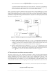
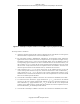
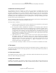
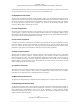
Table Of Contents
- ANSI C63.17-2006 Front Cover
- Title page
- Introduction
- Notice to users
- Participants
- Contents
- American National Standard Methods of Measurement of the Electromagnetic and Operational Compatibility of Unlicensed Personal Communications Services (UPCS) Devices
- 1. Overview
- 2. Normative references
- 3. Definitions, symbols, acronyms, and abbreviations
- 4. Radiated and conducted emissions test methodology
- 4.1 Test facilities and equipment
- 4.2 Test configurations and setup
- 4.3 Transmitted power and monitoring threshold limits
- 4.4 Limits for radiated and conducted tests
- 4.5 Conducted measurements of products with identical collocated transmitting and monitoring antennas
- 4.6 Conducted measurements of products with collocated transmitting and monitoring antennas of different types
- 4.7 Conducted measurements of products with arbitrarily placed transmitting and monitoring antennas
- 4.8 Radiated measurements of products with identical collocated transmitting and monitoring antennas
- 4.9 Radiated measurements of products with collocated transmitting and monitoring antennas of different types
- 4.10 Radiated measurements of products with arbitrarily placed transmitting and monitoring antennas
- 4.11 Manufacturer’s declarations and descriptions
- 5. Measurement instrumentation
- 6. RF measurements
- 7. Monitoring tests
- 8. Time and spectrum window access procedure
- 9. Test report
- 9.1 Test report contents
- 9.2 Applicable standards
- 9.3 Equipment units tested
- 9.4 Test configuration
- 9.5 List of test equipment
- 9.6 Units of measurement
- 9.7 Location of test site
- 9.8 Measurement procedures
- 9.9 Reporting measurement data
- 9.10 General and special conditions
- 9.11 Summary of results
- 9.12 Required signatures
- 9.13 Test report appendixes
- 9.14 Test report disposition
- Annex A (informative) 47CFR15, Subpart D—Rules and test cases for UPCS devices
- Annex B (informative) Radiated and conducted measurement of power output and monitoring thresholds
- Annex C (informative) Options for implementing the tests of Clause 7 and Clause 8

ANSI C63.17-2006
Methods of Measurement of the Electromagnetic and Operational Compatibility of UPCS Devices
Figure 11
8.3.1
—Examples of interference for duplex connection test
If no system clock signal is available to synchronize the interference generators to the system’s frame
timing, establish a connection and use the start of the initiating device’s transmit burst as the
synchronization signal (the transceiver pair used to generate the sync signal must be electromagnetically
isolated from the EUT and the companion device). For an FDMA/TDD system, this procedure will provide
frame synchronization. For a TDMA/TDD system, it will provide slot synchronization, but the transmit
burst can occur on any slot in the transmit portion of the initiating device’s frame. Thus, it is possible that
both interference-free slots from the generators could occur in either the transmit or receive portion of the
EUT’s frame. However, the steps in 8.3.1 and 8.3.2 still apply because the initiating device must monitor
both transmit and receive time/spectrum windows. The success criterion remains that the duplex slot pair is
selected on which the interference power on the “interfered” half of the connection (transmit or receive) is
either below T
L
+ U
M
(for systems that do not meet the criterion for using the upper threshold) or is a
minimum (for systems that meet the criterion for using the upper threshold). For example, in Figure 11(a),
the slot pair labeled “6” should be selected. In Figure 11(b), the frequency pair labeled “3” should be
selected.
The same approach can be applied to systems that use frequency duplexing.
29
For completeness, Figure 12
gives an illustrative example of the interference for an FDMA system using frequency duplexing.
Note that an EUT may pass either the tests of 8.3.1 or the tests of 8.3.2.
Validation of dual access criteria check for EUTs that do not implement the upper
threshold
This test validates proper operation of an EUT that operates according to the provisions of
47CFR15.323(c)(10) using a check of both transmit and receive channels on one end of the link to qualify
both ends of the link for transmissions. If an EUT operates as part of a system that incorporates more than
one kind of initiating device or more than one kind of responding device, then this test will be performed
on each type of initiating device, with each type of responding device.
29
It is expected that most systems in the 1920 MHz to 1930 MHz band will use TDD, because of the need for frequency-duplexed
systems to maintain some frequency separation between the transmit and receive bands. Moreover, the requirement that a device
monitor its own transmit time/spectrum window would tend to make implementation of a conventional frequency-duplexed system
awkward.
36
Copyright © 2007 IEEE. All rights reserved.
Licensed to Sid Sanders. ANSI order X_30788. Downloaded 11/19/2007 2:45 PM. Single user license only. Copying and networking prohibited.