
Manual
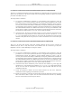
Table Of Contents
- ANSI C63.17-2006 Front Cover
- Title page
- Introduction
- Notice to users
- Participants
- Contents
- American National Standard Methods of Measurement of the Electromagnetic and Operational Compatibility of Unlicensed Personal Communications Services (UPCS) Devices
- 1. Overview
- 2. Normative references
- 3. Definitions, symbols, acronyms, and abbreviations
- 4. Radiated and conducted emissions test methodology
- 4.1 Test facilities and equipment
- 4.2 Test configurations and setup
- 4.3 Transmitted power and monitoring threshold limits
- 4.4 Limits for radiated and conducted tests
- 4.5 Conducted measurements of products with identical collocated transmitting and monitoring antennas
- 4.6 Conducted measurements of products with collocated transmitting and monitoring antennas of different types
- 4.7 Conducted measurements of products with arbitrarily placed transmitting and monitoring antennas
- 4.8 Radiated measurements of products with identical collocated transmitting and monitoring antennas
- 4.9 Radiated measurements of products with collocated transmitting and monitoring antennas of different types
- 4.10 Radiated measurements of products with arbitrarily placed transmitting and monitoring antennas
- 4.11 Manufacturer’s declarations and descriptions
- 5. Measurement instrumentation
- 6. RF measurements
- 7. Monitoring tests
- 8. Time and spectrum window access procedure
- 9. Test report
- 9.1 Test report contents
- 9.2 Applicable standards
- 9.3 Equipment units tested
- 9.4 Test configuration
- 9.5 List of test equipment
- 9.6 Units of measurement
- 9.7 Location of test site
- 9.8 Measurement procedures
- 9.9 Reporting measurement data
- 9.10 General and special conditions
- 9.11 Summary of results
- 9.12 Required signatures
- 9.13 Test report appendixes
- 9.14 Test report disposition
- Annex A (informative) 47CFR15, Subpart D—Rules and test cases for UPCS devices
- Annex B (informative) Radiated and conducted measurement of power output and monitoring thresholds
- Annex C (informative) Options for implementing the tests of Clause 7 and Clause 8

ANSI C63.17-2006
Methods of Measurement of the Electromagnetic and Operational Compatibility of UPCS Devices
8.2.2
8.3
Transmission duration
25
This subclause tests the EUT for compliance to the requirement of 47CFR15.323(c)(3) that the EUT does
not continue to use the same channel without executing the access criteria at least as often as every 8 h.
The test procedure is as follows:
a) Activate the EUT and initiate a communication channel with the companion device, and start a
timer or frame counter.
b) Stop the timer at the end of the EUT transmission on the current time and frequency window.
The EUT fails if the timer is greater than the limit. For an EUT with a frame period of 10/X ms, no more
than 2
880 000 X frames
26
should be transmitted without a break.
Duplex connections
27
This test verifies that the two devices communicating over a duplex connection comply with the access
criteria. Subclause 8.3 is required for and applies only to EUTs that are designated as “initiating” and
“responding” devices, and together satisfy the criteria of 47CFR15.323(c)(10).
28
The manufacturer shall
state whether the criteria of 47CFR15.323(c)(10) are used, and if so, which EUTs are initiating devices and
which devices are responding devices, and shall provide, as part of the test report, appropriate diagrams and
other material to explain procedures for making duplex connections.
The initiating device is the EUT, and the responding device is the companion device tested in conjunction
with the EUT.
To comply with 47CFR15.323(c)(10), the EUT must monitor both its transmit time/spectrum window and
its receive time/spectrum window. The test therefore requires that interference at the EUT on its transmit
and receive time/spectrum windows are varied independently. Figure 11 gives an illustrative example of the
interference, as seen at the EUT. Figure 11(a) represents the interference pattern to a TDMA EUT using
time-division duplexing (TDD) on a single RF carrier and eight duplex time slots per carrier. Figure 11(b)
shows the interference to a frequency-division multiple access (FDMA) EUT using TDD with a single
duplex channel per carrier and eight carriers.
Note that in both the TDMA and FDMA cases, the transmit and receive time and spectrum windows have
different power levels at the EUT. Further, a transmit time and spectrum window may be interference-free
while its paired receive window is not. In the example shown, the power levels of the receive windows are
7 dB higher than those of the transmit windows; in each case, one transmit window and one receive
window is interference-free, but the interference-free transmit and receive windows do not constitute a
duplex pair. In the TDMA example of Figure 11(a), transmit slot 6 and receive slot 2 are interference-free,
and in the FDMA example of Figure 11(b), the transmit slot on frequency 3 and the receive slot on
frequency 6 are interference-free. Producing these interference patterns requires interference generators that
can be synchronized to the frame clock of the EUT and can generate bursts of interference equal to the
duration of the EUT transmit/receive bursts.
25
See 47CFR15.323(c)(3).
26
(3 600 s/h)(8 h)/(10/X ms/frame) = 2 880 000.
27
See 47CFR15.323(c)(10)
28
See 47CFR15.323(c)(10), which specifies that for the initiating device “both the intended transmit and receive time and spectrum
windows [must] meet the access criteria.” This is interpreted to mean, in the case of LIC operation per 15.323(c)(5), that the greatest
of the monitored level on the transmit and receive time/spectrum windows is used to determine the least interfered time/spectrum
window duplex pair.
35
Copyright © 2007 IEEE. All rights reserved.
Licensed to Sid Sanders. ANSI order X_30788. Downloaded 11/19/2007 2:45 PM. Single user license only. Copying and networking prohibited.