
Manual
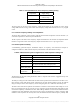
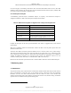
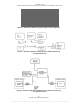
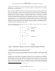
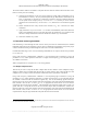
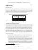
Table Of Contents
- ANSI C63.17-2006 Front Cover
- Title page
- Introduction
- Notice to users
- Participants
- Contents
- American National Standard Methods of Measurement of the Electromagnetic and Operational Compatibility of Unlicensed Personal Communications Services (UPCS) Devices
- 1. Overview
- 2. Normative references
- 3. Definitions, symbols, acronyms, and abbreviations
- 4. Radiated and conducted emissions test methodology
- 4.1 Test facilities and equipment
- 4.2 Test configurations and setup
- 4.3 Transmitted power and monitoring threshold limits
- 4.4 Limits for radiated and conducted tests
- 4.5 Conducted measurements of products with identical collocated transmitting and monitoring antennas
- 4.6 Conducted measurements of products with collocated transmitting and monitoring antennas of different types
- 4.7 Conducted measurements of products with arbitrarily placed transmitting and monitoring antennas
- 4.8 Radiated measurements of products with identical collocated transmitting and monitoring antennas
- 4.9 Radiated measurements of products with collocated transmitting and monitoring antennas of different types
- 4.10 Radiated measurements of products with arbitrarily placed transmitting and monitoring antennas
- 4.11 Manufacturer’s declarations and descriptions
- 5. Measurement instrumentation
- 6. RF measurements
- 7. Monitoring tests
- 8. Time and spectrum window access procedure
- 9. Test report
- 9.1 Test report contents
- 9.2 Applicable standards
- 9.3 Equipment units tested
- 9.4 Test configuration
- 9.5 List of test equipment
- 9.6 Units of measurement
- 9.7 Location of test site
- 9.8 Measurement procedures
- 9.9 Reporting measurement data
- 9.10 General and special conditions
- 9.11 Summary of results
- 9.12 Required signatures
- 9.13 Test report appendixes
- 9.14 Test report disposition
- Annex A (informative) 47CFR15, Subpart D—Rules and test cases for UPCS devices
- Annex B (informative) Radiated and conducted measurement of power output and monitoring thresholds
- Annex C (informative) Options for implementing the tests of Clause 7 and Clause 8

ANSI C63.17-2006
Methods of Measurement of the Electromagnetic and Operational Compatibility of UPCS Devices
7.4.2
Table 10
More detailed test
The following (more detailed) test verifies the operation of the EUT by probing the shape of the emissions
and the monitoring filter.
From the measurement of the emission bandwidth (see 6.1.5), find the two frequency pairs above and
below the frequency of the maximum level of the modulated carrier, most removed from each other, where
the signal levels are 6 dB and 12 dB below the peak level of the modulated carrier. With an unmodulated
interfering signal set at each of these frequencies and set at a level 6 dB and 12 dB above T
U
+ U
M
or T
L
+
U
M
as appropriate for EUTs that do or do not meet the requirements for using the upper threshold. Verify
that the EUT will not transmit. Table 10 summarizes these test frequencies and levels.
—Test frequencies and levels for monitoring filter test
Test frequency
Test level
(above T
U
+ U
M
or
T
L
+ U
M
, as appropriate)
−6 dB points 6 dB
−12 dB points 12 dB
Note that the test at the center frequency is equivalent to part of the test of 7.3.
7.5
Reaction time and monitoring interval
20
The reaction time is the minimum duration of the interference present during the monitoring interval that
must be detected by the EUT so as to determine that the monitored time and spectrum window is occupied.
The objective of the test is thus to demonstrate that the EUT defers use of a channel when the interfering
signals are at least of a time duration that exceeds the allowed limit. An example radiated arrangement of
the test equipment is shown in Figure 10. A similar conducted arrangement could be used. The gate device
may be a controlled amplifier that is used to pulse the channel interference to provide pulses of the required
time duration and position. Such a test requires that the interference be positioned within a defined
monitoring interval synchronized to the frame timing of the EUT, and so a derived frame synchronization
signal is acquired from the monitoring EUT and applied to the pulse generator. An alternative arrangement
would be to connect the output of the pulse generator directly to the “pulse modulation” input of the
channel interference generator, if it is so equipped.
The test procedure is as follows:
a) Using either frequency administration commands or out-of-operating-region interference (using
the procedures in 7.2.3), restrict operation of the EUT to a single transmit carrier frequency f
1
,
and verify that the EUT can establish a connection with no interference applied on f
1
.
b) Apply time-synchronized, pulsed interference on f
1
at the pulsed level T
U
+ U
M
or T
L
+ U
M
as
appropriate for EUTs that do or do not meet the requirements for using the upper threshold. For
a system with 10 ms frame time and N timeslots per frame, the channel interference should be
pulsed with N pulses in a 10 ms repetition period (the accuracy of the repetition rate to be ± 10
ppm or better) with a common variable pulse width. The rise and fall times of the interference
bursts shall be less than 1 µs from the 10% to 90% of the final amplitude. The interference pulse
shall be of constant amplitude during its burst (± 5%). EUTs that divide the use of the channel
in time into a number of timeslots (N ≠ 1) may find it necessary for the pulsed interference to be
20
See 47CFR15.323(c)(1), 47CFR15.323(c)(5), and 47CFR15.323 (c)(7).
30
Copyright © 2007 IEEE. All rights reserved.
Licensed to Sid Sanders. ANSI order X_30788. Downloaded 11/19/2007 2:45 PM. Single user license only. Copying and networking prohibited.