
Manual
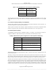
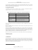
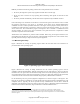
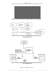
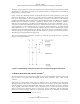
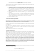
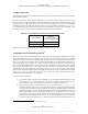
Table Of Contents
- ANSI C63.17-2006 Front Cover
- Title page
- Introduction
- Notice to users
- Participants
- Contents
- American National Standard Methods of Measurement of the Electromagnetic and Operational Compatibility of Unlicensed Personal Communications Services (UPCS) Devices
- 1. Overview
- 2. Normative references
- 3. Definitions, symbols, acronyms, and abbreviations
- 4. Radiated and conducted emissions test methodology
- 4.1 Test facilities and equipment
- 4.2 Test configurations and setup
- 4.3 Transmitted power and monitoring threshold limits
- 4.4 Limits for radiated and conducted tests
- 4.5 Conducted measurements of products with identical collocated transmitting and monitoring antennas
- 4.6 Conducted measurements of products with collocated transmitting and monitoring antennas of different types
- 4.7 Conducted measurements of products with arbitrarily placed transmitting and monitoring antennas
- 4.8 Radiated measurements of products with identical collocated transmitting and monitoring antennas
- 4.9 Radiated measurements of products with collocated transmitting and monitoring antennas of different types
- 4.10 Radiated measurements of products with arbitrarily placed transmitting and monitoring antennas
- 4.11 Manufacturer’s declarations and descriptions
- 5. Measurement instrumentation
- 6. RF measurements
- 7. Monitoring tests
- 8. Time and spectrum window access procedure
- 9. Test report
- 9.1 Test report contents
- 9.2 Applicable standards
- 9.3 Equipment units tested
- 9.4 Test configuration
- 9.5 List of test equipment
- 9.6 Units of measurement
- 9.7 Location of test site
- 9.8 Measurement procedures
- 9.9 Reporting measurement data
- 9.10 General and special conditions
- 9.11 Summary of results
- 9.12 Required signatures
- 9.13 Test report appendixes
- 9.14 Test report disposition
- Annex A (informative) 47CFR15, Subpart D—Rules and test cases for UPCS devices
- Annex B (informative) Radiated and conducted measurement of power output and monitoring thresholds
- Annex C (informative) Options for implementing the tests of Clause 7 and Clause 8

ANSI C63.17-2006
Methods of Measurement of the Electromagnetic and Operational Compatibility of UPCS Devices
7.3.2
7.3.3
7.3.4
Upper threshold for EUTs that implement the LIC procedure
Choose one of the following two alternative tests:
a) Set the EUT, by administrative commands, to operate on the carrier closest to the center of the
band. By an interference generator, apply interference on that channel at an in-band level at the
EUT of T
U
+ U
M
+ 10 dB. Lower the interference until the EUT can transmit. If the EUT first
transmits at an interference level greater than T
U
+ U
M
, the EUT fails the test.
b) By a multicarrier interference generator, apply to the EUT uniform CW interference on all
system carriers each at level T
U
+ U
M
+ 10 dB. Lower the interference uniformly on all carriers
until the EUT can transmit. If the EUT first transmits at a per-carrier interference level greater
than T
U
+ U
M
, the EUT fails the test.
LIC procedure test
A practical implementation of ordering LICs is to group them in bins according to measured signal
strength, with generally a maximum difference between individual bin limits chosen to meet the 6 dB
resolution requirement of 47CFR15.323(c)(5). With such an implementation, ordering within a bin for the
lowest interference is not required, and all channels in a bin are considered equally good. The lowest bin
may be the bin for “quiet” channels, and by exception has no lower bin limit, and an upper bin limit that
must only be below the calculated lower threshold. “Quiet” channels may be accessed without any LIC
ordering; the limit for unordered channels must only be below the lower threshold.
The LIC test procedure is as follows:
a) Allow EUT transmission on only two carrier frequencies, which will be designated f
1
and f
2
.
This limitation to carriers f
1
and f
2
is performed preferably by administration commands for the
EUT, or alternatively by applying by a multicarrier interference generator uniform interference
on all system carriers except f
1
and f
2
, at a level of T
U
+ U
M
, in-band per carrier.
b) Apply interference to the EUT on f
1
at a level of T
L
+ U
M
+ 7 dB and on f
2
at a level of T
L
+ U
M
.
Initiate transmission. The EUT should transmit on f
2
. Terminate the connection. Repeat five
times. If the EUT transmits once on f
1
, the test failed.
c) Apply interference to the EUT on f
1
at a level of T
L
+ U
M
and on f
2
at a level of T
L
+ U
M
+ 7 dB.
Initiate transmission. The EUT should transmit on f
1
. Terminate the connection. Repeat five
times. If the EUT transmits once on f
2
, the test failed.
d) Apply interference to the EUT on f
1
at a level of T
L
+ U
M
+ 1 dB and on f
2
at a level of T
L
+ U
M
− 6 dB. Initiate transmission. If the EUT transmits on f
2
, terminate the connection. Repeat five
times. If the EUT transmits once on f
1
, the test failed.
e) Apply interference to the EUT on f
1
at a level of T
L
+ U
M
− 6 dB and on f
2
at a level of T
L
+ U
M
+ 1 dB. Initiate transmission. If the EUT transmits on f
1
, terminate the connection. Repeat five
times. If the EUT transmits once on f
2
, the test failed.
Selected channel confirmation
17
Some types of EUTs may prescan available channels and store the detected power levels in memory to
facilitate fast selection of a channel when access is required. Since some amount of time is required for a
complete scan,
18
the stored power level for a selected channel may have “aged” since the measurement was
taken. The EUT is therefore required to remonitor the selected channel immediately prior to transmission.
17
See 47CFR15.323(c)(1) and 47CFR15.323(c)(5).
18
Up to 10 s is allowed for devices operating under 47CFR15.323(c)(5).
28
Copyright © 2007 IEEE. All rights reserved.
Licensed to Sid Sanders. ANSI order X_30788. Downloaded 11/19/2007 2:45 PM. Single user license only. Copying and networking prohibited.