
Manual
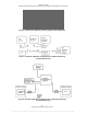
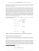
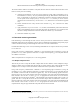
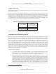
Table Of Contents
- ANSI C63.17-2006 Front Cover
- Title page
- Introduction
- Notice to users
- Participants
- Contents
- American National Standard Methods of Measurement of the Electromagnetic and Operational Compatibility of Unlicensed Personal Communications Services (UPCS) Devices
- 1. Overview
- 2. Normative references
- 3. Definitions, symbols, acronyms, and abbreviations
- 4. Radiated and conducted emissions test methodology
- 4.1 Test facilities and equipment
- 4.2 Test configurations and setup
- 4.3 Transmitted power and monitoring threshold limits
- 4.4 Limits for radiated and conducted tests
- 4.5 Conducted measurements of products with identical collocated transmitting and monitoring antennas
- 4.6 Conducted measurements of products with collocated transmitting and monitoring antennas of different types
- 4.7 Conducted measurements of products with arbitrarily placed transmitting and monitoring antennas
- 4.8 Radiated measurements of products with identical collocated transmitting and monitoring antennas
- 4.9 Radiated measurements of products with collocated transmitting and monitoring antennas of different types
- 4.10 Radiated measurements of products with arbitrarily placed transmitting and monitoring antennas
- 4.11 Manufacturer’s declarations and descriptions
- 5. Measurement instrumentation
- 6. RF measurements
- 7. Monitoring tests
- 8. Time and spectrum window access procedure
- 9. Test report
- 9.1 Test report contents
- 9.2 Applicable standards
- 9.3 Equipment units tested
- 9.4 Test configuration
- 9.5 List of test equipment
- 9.6 Units of measurement
- 9.7 Location of test site
- 9.8 Measurement procedures
- 9.9 Reporting measurement data
- 9.10 General and special conditions
- 9.11 Summary of results
- 9.12 Required signatures
- 9.13 Test report appendixes
- 9.14 Test report disposition
- Annex A (informative) 47CFR15, Subpart D—Rules and test cases for UPCS devices
- Annex B (informative) Radiated and conducted measurement of power output and monitoring thresholds
- Annex C (informative) Options for implementing the tests of Clause 7 and Clause 8
ANSI C63.17-2006
Methods of Measurement of the Electromagnetic and Operational Compatibility of UPCS Devices
deference response of the companion device. This implies that for the conducted case (Figure 8), the
attenuation ACD shall be at least 10 dB higher than the attenuation AEUT. This is to ensure that the
companion device does not defer transmissions due to interference on its transmit channel and/or
corresponding duplex receive channel when the interference levels are set to a level appropriate to test the
EUT. Furthermore, the signals from the companion device must be received by the EUT with much higher
power (typically > 20 dB) than the power of the interference into the EUT. This is to ensure that the EUT
can properly receive the transmissions from companion device when the interference levels are set to test
the EUT. In addition, if the companion device is required to be able to receive signals from the EUT, the
signals from the EUT must be received by the companion device with much higher power (typically
> 20 dB) than the power of the interference into the companion device.
In any of the steps in 7.3.1, 7.3.2, 7.3.3, and 7.3.4, the path loss between the EUT and the companion
device must be adjusted for reliable communications in the absence of interference. If the EUT fails to
communicate reliably during testing, attenuation between the EUT and the companion device may be
adjusted as long as the interference levels applied to the EUT are not changed.
The manufacturer shall include, in its test report, a declaration of the relevant monitoring thresholds as well
as an explanation of the monitoring and channel selection protocols, including any necessary diagrams.
(Note that for the LIC procedure, the requirement “to have monitored all channels” in 47CFR15.323(c)(5)
does not include access channels on so-called blind slots, as long as those access channels are not included
in the ordered list of LICs. A blind slot is a time slot that the EUT cannot access because it is transmitting
or receiving at that time. Additional blind slots are created by the speed of the EUT frequency synthesizer
and its ability to change carriers within the guard band between slots.)
The steps in 7.3.1, 7.3.2, 7.3.3, and 7.3.4 apply directly to conductive testing. For radiative testing, the
threshold power levels specified below must be translated to the corresponding transmit power levels for
the reference antenna, as discussed in Clause 4 and Annex B.
The interference test signals may be either CW or modulated in the same way as the EUT transmission.
Adjust the out-of-operating-region interference (if used) to the levels appropriate to the test (i.e., lower
threshold, LIC, upper threshold) per 7.2.3 of this standard.
When these tests are performed on an EUT transmitting signaling or control information, transmission on
an existing channel (initiated before the interference is applied) may continue for up to 30 s before channel
selection is affected by the interference. For such EUTs, it may be necessary to wait 30 s to verify proper
monitoring and establish threshold being measured. Similarly, the EUT should continue to transmit on a
channel consistent with the interference, which is applied as long as the interference exists.
7.3.1 Lower threshold for EUTs that do not implement the LIC procedure
Choose one of the following two alternative tests:
a) Set the EUT, by administrative commands, to operate on the carrier closest to the center of the
band. By an interference generator, apply interference on that channel at an in-band level at the
EUT of T
L
+ U
M
+ 10 dB. Lower the interference until the EUT can transmit. If the EUT first
transmits at an interference level greater than T
L
+ U
M
, the EUT fails the test.
b) By a multicarrier interference generator, apply to the EUT uniform CW interference on all
system carriers each at level T
L
+ U
M
+ 10 dB. Lower the interference uniformly on all carriers
until the EUT can transmit. If the EUT first transmits at a per-carrier interference level greater
than T
L
+ U
M
, the EUT fails the test.
27
Copyright © 2007 IEEE. All rights reserved.
Licensed to Sid Sanders. ANSI order X_30788. Downloaded 11/19/2007 2:45 PM. Single user license only. Copying and networking prohibited.