
Manual
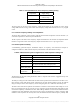
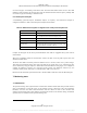
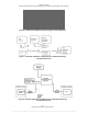
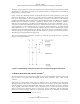
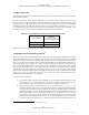
Table Of Contents
- ANSI C63.17-2006 Front Cover
- Title page
- Introduction
- Notice to users
- Participants
- Contents
- American National Standard Methods of Measurement of the Electromagnetic and Operational Compatibility of Unlicensed Personal Communications Services (UPCS) Devices
- 1. Overview
- 2. Normative references
- 3. Definitions, symbols, acronyms, and abbreviations
- 4. Radiated and conducted emissions test methodology
- 4.1 Test facilities and equipment
- 4.2 Test configurations and setup
- 4.3 Transmitted power and monitoring threshold limits
- 4.4 Limits for radiated and conducted tests
- 4.5 Conducted measurements of products with identical collocated transmitting and monitoring antennas
- 4.6 Conducted measurements of products with collocated transmitting and monitoring antennas of different types
- 4.7 Conducted measurements of products with arbitrarily placed transmitting and monitoring antennas
- 4.8 Radiated measurements of products with identical collocated transmitting and monitoring antennas
- 4.9 Radiated measurements of products with collocated transmitting and monitoring antennas of different types
- 4.10 Radiated measurements of products with arbitrarily placed transmitting and monitoring antennas
- 4.11 Manufacturer’s declarations and descriptions
- 5. Measurement instrumentation
- 6. RF measurements
- 7. Monitoring tests
- 8. Time and spectrum window access procedure
- 9. Test report
- 9.1 Test report contents
- 9.2 Applicable standards
- 9.3 Equipment units tested
- 9.4 Test configuration
- 9.5 List of test equipment
- 9.6 Units of measurement
- 9.7 Location of test site
- 9.8 Measurement procedures
- 9.9 Reporting measurement data
- 9.10 General and special conditions
- 9.11 Summary of results
- 9.12 Required signatures
- 9.13 Test report appendixes
- 9.14 Test report disposition
- Annex A (informative) 47CFR15, Subpart D—Rules and test cases for UPCS devices
- Annex B (informative) Radiated and conducted measurement of power output and monitoring thresholds
- Annex C (informative) Options for implementing the tests of Clause 7 and Clause 8

ANSI C63.17-2006
Methods of Measurement of the Electromagnetic and Operational Compatibility of UPCS Devices
7.1.2
7.1.3
7.1.4
7.2
7.2.1
7.2.2
7.2.3
Monitoring test procedure—general
The threshold used for channel access deferral is based on the power and emission bandwidth
measurements of 6.1.2 and 6.1.3.
Each test will generally consist of the following steps:
a) Using either carrier and/or access channel administration commands or out-of-operating-region
interference (see 7.2.3), restrict operation of the EUT to a target channel or set of channels on
which the test will be performed. Initiate transmission without the presence of interference on
the target region to verify that the EUT is operating. The communication is then stopped.
b) Introduce interference on the target channel or channels at the prescribed level and time duration
as appropriate to the EUT and verify that the EUT defers use of that channel or channels when
initiation of a connection is attempted.
c) The EUT passes when it operates only in the allowed combinations of operating environments.
Standard test frequencies
Monitoring tests shall be performed on the carrier closest to the center of the band, except when two or all
carriers are specified. When two carriers are specified, the carriers adjacent to the carrier closest to the
center of the band may be used.
Timeslot and carrier equivalence
The monitoring procedure tests of Clause 7 that specify interference applied on various carriers may be
implemented on a single carrier using interference synchronized with the timeslot structure, with the
interference level adjusted by timeslot equivalently to the adjustments specified for interference present on
individual carriers.
Calibration of levels
Calculation of thresholds
15
Calculate the upper threshold limit T
U
according to the provisions of 4.3.3, and the lower threshold limit T
L
according to the provisions of 4.3.4.
Calibration of test interference field strength (radiated technique)
Refer to Clause 4 and Annex B.
Procedures for using out-of-operating-region interference
The multicarrier generator in C.1 is an interference source that can generate independently controlled (on or
off) CW signals on the center frequencies of all EUT carriers. This generator can be used to apply out-of-
operating-region interference to target specific frequency ranges or time intervals for threshold testing by
blocking the other frequencies and/or timeslots, unless the frequency selectivity of the EUT is extremely
poor. The procedures given here are intended to ensure that residual power from the generator falling on
the target (unblocked) frequency does not corrupt the test.
15
See 47CFR15.321(c)(2), 47CFR15.321(c)(7), 47CFR15.323(c)(2), 47CFR15.323(c)(5), and 47CFR15.323(c)(9).
25
Copyright © 2007 IEEE. All rights reserved.
Licensed to Sid Sanders. ANSI order X_30788. Downloaded 11/19/2007 2:45 PM. Single user license only. Copying and networking prohibited.