
Manual
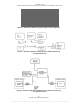
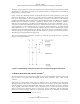
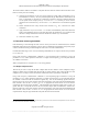
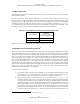
Table Of Contents
- ANSI C63.17-2006 Front Cover
- Title page
- Introduction
- Notice to users
- Participants
- Contents
- American National Standard Methods of Measurement of the Electromagnetic and Operational Compatibility of Unlicensed Personal Communications Services (UPCS) Devices
- 1. Overview
- 2. Normative references
- 3. Definitions, symbols, acronyms, and abbreviations
- 4. Radiated and conducted emissions test methodology
- 4.1 Test facilities and equipment
- 4.2 Test configurations and setup
- 4.3 Transmitted power and monitoring threshold limits
- 4.4 Limits for radiated and conducted tests
- 4.5 Conducted measurements of products with identical collocated transmitting and monitoring antennas
- 4.6 Conducted measurements of products with collocated transmitting and monitoring antennas of different types
- 4.7 Conducted measurements of products with arbitrarily placed transmitting and monitoring antennas
- 4.8 Radiated measurements of products with identical collocated transmitting and monitoring antennas
- 4.9 Radiated measurements of products with collocated transmitting and monitoring antennas of different types
- 4.10 Radiated measurements of products with arbitrarily placed transmitting and monitoring antennas
- 4.11 Manufacturer’s declarations and descriptions
- 5. Measurement instrumentation
- 6. RF measurements
- 7. Monitoring tests
- 8. Time and spectrum window access procedure
- 9. Test report
- 9.1 Test report contents
- 9.2 Applicable standards
- 9.3 Equipment units tested
- 9.4 Test configuration
- 9.5 List of test equipment
- 9.6 Units of measurement
- 9.7 Location of test site
- 9.8 Measurement procedures
- 9.9 Reporting measurement data
- 9.10 General and special conditions
- 9.11 Summary of results
- 9.12 Required signatures
- 9.13 Test report appendixes
- 9.14 Test report disposition
- Annex A (informative) 47CFR15, Subpart D—Rules and test cases for UPCS devices
- Annex B (informative) Radiated and conducted measurement of power output and monitoring thresholds
- Annex C (informative) Options for implementing the tests of Clause 7 and Clause 8

ANSI C63.17-2006
Methods of Measurement of the Electromagnetic and Operational Compatibility of UPCS Devices
Difficulty in definitive monitoring testing comes from several potential sources as follows:
⎯ EUTs may be designed to operate only together with other devices of like type.
⎯ EUTs may select a channel or stop operating when interfering radio signals are detected in their
channel.
⎯ EUTs may transmit intermittently, and thus their modes of operation may be difficult to detect.
In the monitoring tests, interference is introduced to some unused regions of the band in order to confine
the operation of the EUT to one region, or, if available, carrier and/or access channel administration
commands are used to confine operation of the EUT to one region. For the purposes of many of the tests, it
is sufficient to confine the EUT to operate in a restricted a region in the frequency domain, e.g., one or two
carriers of the EUT. This is illustrated by Figure 5 and Figure 6. Since a channel is a combined time and
spectrum window, for some tests it may be desirable to use gated interference to implement a similar
restriction of operation in the time domain.
Administrative test commands are preferred when available. When using out-of-region interference, the
power falling into the adjacent carrier of the EUT could potentially corrupt the test on the wanted carrier,
especially if the EUT has poor adjacent channel rejection properties.
7.1.1 Monitoring test setup
Figure 5 illustrates the concept of operating regions within the band and shows how interference is
provided outside of the operating region.
Figure 5
—Operating region within UPCS band
Figure 6 illustrates the concept of adding interference into the selected operating region to test for
compliance with the threshold limits. With this arrangement, the test requirement is to observe if the EUT
transmits in the one region where the threshold is being tested. The out-of-operating-region interference is
not required during the tests if the EUT is designed to operate in a sngle fixed channel of the UPCS band,
or if the EUT can be restricted to selected channels using frequency administration commands.
13
For the monitoring tests, the general equipment configurations are shown in Figure 7 and Figure 8. The
EUT may be arranged to communicate via radio signals between itself and another compatible device (the
companion device). Typically, the devices provide two-way communications, and one device should be
designated as the monitoring transceiver under test (the EUT). Figure 7 illustrates radiated communication
between the EUT and the instruments; Figure 8 illustrates conducted communication.
14
13
Some UPCS devices may have the capability to restrict the device’s operation to a subset of the available channels.
14
The interference antenna must transmit at least 10 dB higher power to the monitoring EUT than to the companion device.
Otherwise, the operation of the EUT may be masked by the undesired response of the companion device to an above-threshold
interference signal.
23
Copyright © 2007 IEEE. All rights reserved.
Licensed to Sid Sanders. ANSI order X_30788. Downloaded 11/19/2007 2:45 PM. Single user license only. Copying and networking prohibited.