
Manual
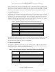
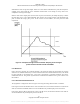
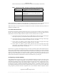
Table Of Contents
- ANSI C63.17-2006 Front Cover
- Title page
- Introduction
- Notice to users
- Participants
- Contents
- American National Standard Methods of Measurement of the Electromagnetic and Operational Compatibility of Unlicensed Personal Communications Services (UPCS) Devices
- 1. Overview
- 2. Normative references
- 3. Definitions, symbols, acronyms, and abbreviations
- 4. Radiated and conducted emissions test methodology
- 4.1 Test facilities and equipment
- 4.2 Test configurations and setup
- 4.3 Transmitted power and monitoring threshold limits
- 4.4 Limits for radiated and conducted tests
- 4.5 Conducted measurements of products with identical collocated transmitting and monitoring antennas
- 4.6 Conducted measurements of products with collocated transmitting and monitoring antennas of different types
- 4.7 Conducted measurements of products with arbitrarily placed transmitting and monitoring antennas
- 4.8 Radiated measurements of products with identical collocated transmitting and monitoring antennas
- 4.9 Radiated measurements of products with collocated transmitting and monitoring antennas of different types
- 4.10 Radiated measurements of products with arbitrarily placed transmitting and monitoring antennas
- 4.11 Manufacturer’s declarations and descriptions
- 5. Measurement instrumentation
- 6. RF measurements
- 7. Monitoring tests
- 8. Time and spectrum window access procedure
- 9. Test report
- 9.1 Test report contents
- 9.2 Applicable standards
- 9.3 Equipment units tested
- 9.4 Test configuration
- 9.5 List of test equipment
- 9.6 Units of measurement
- 9.7 Location of test site
- 9.8 Measurement procedures
- 9.9 Reporting measurement data
- 9.10 General and special conditions
- 9.11 Summary of results
- 9.12 Required signatures
- 9.13 Test report appendixes
- 9.14 Test report disposition
- Annex A (informative) 47CFR15, Subpart D—Rules and test cases for UPCS devices
- Annex B (informative) Radiated and conducted measurement of power output and monitoring thresholds
- Annex C (informative) Options for implementing the tests of Clause 7 and Clause 8

ANSI C63.17-2006
Methods of Measurement of the Electromagnetic and Operational Compatibility of UPCS Devices
Table 5 —Spectrum analyzer settings for measuring in-band emissions
RBW Approximately 1% of the emission bandwidth (B)
Video bandwidth 3 × RBW
Sweep time
The sweep time shall be sufficiently slow that the swept
frequency rate shall not exceed one RBW per three
transmit bursts.
Number of sweeps Sufficient to stabilize the trace
Amplitude scale Log
Detection Peak detection and max hold enabled
Span Approximately equal to 3.5 B
In the region between 3B and the UPCS band edge, as measured from the center of the RF carrier, the
measured emission level shall not exceed 60 dB below the permitted peak power for the EUT.
Where these limits are more stringent than 47CFR15.209, the limits of 47CFR15.209 take precedence as
indicated in 47CFR15.319(g).
6.1.6.2
6.2
Out-of-band emissions
Out-of-band tests shall be performed with the RF carrier set to the lowest and highest carriers defined by
the EUT. The spectrum analyzer settings for in-band unwanted emissions in 6.1.6.1 also apply to out-of-
band emissions. The EUT shall pass the tests of item a), item b), and either item c) or item d).
a) In the region between the band edges and 1.25 MHz below and above the lower and the upper
band edges, respectively, the measured emission level shall not exceed −9.5 dBm.
b) In the region between 1.25 and 2.5 MHz below and above the lower and the upper band edges,
respectively, the measured emission level shall not exceed −29.5 dBm.
c) In the region at 2.5 MHz or greater below and above the lower and upper band edges,
respectively, the measured emission level shall not exceed −39.5 dBm.
d) In the region at 2.5 MHz or greater below and above the lower and upper band edges,
respectively, the measured emission level shall not exceed the limits of 47CFR15.209.
Measurement shall be made as a radiated test.
UPCS devices, in general, include digital circuitry not directly associated with the radio transmitter and are
subject to the requirements for unintentional radiators as described in 47CFR15.109, for both in-band and
out-of-band emissions. These emissions shall be measured with the EUT operating in receive and transmit
modes. For the transmit mode, do not measure within 3.75 MHz or 3B, whichever is the largest, of the
edges of the band. Emissions that are directly caused by digital circuits in the transmit path do not have to
meet 47CFR15.109 limits, but shall meet those limits as mentioned in the preceding list.
Frequency and time stability
If the radiated method is used, refer to Clause 4 for configuration details. If the devices provide two-way
communications, one should be designated as the EUT, with its transmitter under test, and the other is
designated the companion device. If the conducted method is used, the EUT and its companion device may
be connected with shielded coaxial cable through a splitter or similar device, or the companion device may
be placed close enough to establish communications through radiation. An attenuator should be placed in
the conducted path between the EUT and its companion device (if present) to prevent test results from
being corrupted by emissions from the companion device. The attenuation should be adjusted to allow
19
Copyright © 2007 IEEE. All rights reserved.
Licensed to Sid Sanders. ANSI order X_30788. Downloaded 11/19/2007 2:45 PM. Single user license only. Copying and networking prohibited.